Table of Contents
Advertisement
Quick Links
HEC-RIM
© ELECTROLUX HOME PRODUCTS
ITALY S.p.A.
Spares Operations Italy
Corso Lino Zanussi,30
I - 33080 PORCIA /PN (ITALY)
Fax +39 0434 394096
Edition: 2007-08-11
Publication
number
599 70 40-15
Structural characteristics,
EN
electrical components,
SERVICE MANUAL
WASHING
HEC-ARCHED
Washer-dryers
HEC-RIM
HEC-ARCHED
accessibility
Advertisement
Table of Contents

Related Manuals for Electrolux HEC-RIM SEries


Summary of Contents for Electrolux HEC-RIM SEries
-
Page 1: Service Manual
SERVICE MANUAL WASHING HEC-RIM HEC-ARCHED Washer-dryers © ELECTROLUX HOME PRODUCTS Publication ITALY S.p.A. number Spares Operations Italy HEC-RIM Corso Lino Zanussi,30 HEC-ARCHED I - 33080 PORCIA /PN (ITALY) 599 70 40-15 Structural characteristics, Fax +39 0434 394096 electrical components, accessibility... - Page 2 2/14 SOI/DT 2007-11 dmm 599 70 40-15...
-
Page 3: Table Of Contents
CONTENTS PURPOSE OF THIS MANUAL ....................... 4 PRECAUTIONS ............................4 DRYING SYSTEM: HYDRAULIC CIRCUIT.................... 5 DRYING CIRCUIT ..........................6 COMPONENTS ............................7 Fan ..............................7 Heating element casing ........................7 Duct..............................8 Drying condenser..........................8 ACCESSIBILITY ............................. 9 Work top............................. 9 Electric fan ............................ -
Page 4: Purpose Of This Manual
PURPOSE OF THIS MANUAL The purpose of this manual is to provide service engineers who already have the basic skills necessary to repair washing machines with specific information concerning the drying system featured in washer-dryers with the HEC cabinet. For information regarding the structural characteristics and the washing systems, refer to Service Manual: N°... -
Page 5: Drying System: Hydraulic Circuit
DRYING SYSTEM: HYDRAULIC CIRCUIT 1. Solenoid valve 2. Tube between solenoid valve and coupling 3. Coupling (Air-Break) 4. Condensation intake hose and vapour outlet The condensation is ducted by one of the sections of the cold water solenoid valve (1), which has a delivery of about 0.4 litres per minute. -
Page 6: Drying Circuit
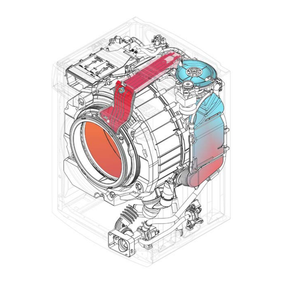
4 DRYING CIRCUIT 1. Fan 8. Solenoid valve 2. Electric fan 9. Condensation intake tube and vapour 3. Casing and heating element outlet 4. Duct 10. Tube between solenoid valve and air 5. Bellow seal break 6. Coupling between 11. Coupling (Air-break) condenser 12. -
Page 7: Components
5 COMPONENTS 5.1 Fan 1. Fan unit 2. Fan motor 3. Drive belt The fan ducts the air from the condenser to the casing containing the heating elements. The fan is powered by the fan motor via a drive belt. 1. -
Page 8: Duct
5.3 Duct 1. Duct 2. NTC temperature sensor (drying) The air from the heating element(s) is ducted directly into the tub through the bellow seal. An NTC sensor fitted to the tub measures the drying temperature. This sensor consists of two identical PVC elements welded together face to face and anchored by a screw to the front panel. -
Page 9: Accessibility
6 ACCESSIBILITY 6.1 Work top Remove the two screws which secure the top to the rear of the appliance, then push the top towards the rear and remove. 6.2 Electric fan Remove the screw which secures the plastic duct to the front panel. -
Page 10: Drying Heating Element
Turn the fan unit clockwise as shown in the figure. Position the fan between the condenser and the heating element casing. Lift and remove the fan unit. 6.3 Drying heating element Remove the screw which secures the plastic duct to the heating element casing. -
Page 11: Drying Sensor (Duct)
6.4 Drying sensor (duct) Detach the connectors. Remove the two screws which secure the sensor to the duct and remove the sensor. When re-assembling, ensure that the gasket is correctly positioned. 6.5 Thermostats 6.5.1 Manual-reset thermostat Detach the connectors. Remove the two screws which secure the thermostat to the duct and remove the thermostat. -
Page 12: Condenser
6.7 Condenser Remove the work-top. Remove the screws which secure the rear panel to the cabinet. Drain any residual water from the drain filter. Remove the fan unit (see paragraph 6.2 page 9). Remove the humidity sensor (see paragraph 6.6 page 11). Remove the screw from the clamp which secures the sleeve to the tub. -
Page 13: Bellow Seal
To detach the external drain hose, remove the screw from the clamp which secures the external drain hose to the internal drain hose. Remove the screw (g). Press the catch (h). Move the condenser upwards and inwards in order to detach it from the cabinet (see opposite fig.). -
Page 14: Wd Circuit Board
6.9 WD Circuit board Remove the screw which secures the circuit board to the cross-member. If necessary, cut the cable ties. On completion of repairs, replace the cable ties. 14/14 SOI/DT 2007-11 dmm 599 70 40-15...
Need help?
Do you have a question about the HEC-RIM SEries and is the answer not in the manual?
Questions and answers