Table of Contents
Advertisement
Quick Links
Advertisement
Table of Contents

Subscribe to Our Youtube Channel
Related Manuals for Comtrend Corporation CT-5624


Summary of Contents for Comtrend Corporation CT-5624
-
Page 1: User Manual
CT-5624 4-Port ADSL2+ Router User Manual Version A1.2, June 9, 2008 261085-005... - Page 2 Copyright Copyright©2008 Comtrend Corporation. All rights reserved. The information contained herein is proprietary to Comtrend Corporation. No part of this document may be translated, transcribed, reproduced, in any form, or by any means without prior written consent of Comtrend Corporation.
-
Page 3: Table Of Contents
Table of Contents CHAPTER 1 INTRODUCTION......................4 CHAPTER 2 INSTALLATION......................5 CHAPTER 3 CONNECTING THE HARDWARE ................6 CHAPTER 4 LOGIN VIA THE WEB BROWSER .................7 4.1 IP C ..........................7 ONFIGURATION 4.2 L ..........................8 OGIN ROCEDURE 4.3 D .........................9 EFAULT ETTINGS CHAPTER 5 DEVICE INFORMATION..................10 5.1 WAN ............................. - Page 4 9.5.2 IP Addresses ........................69 9.5.3 Passwords ........................70 9.6 U ........................71 PDATE SOFTWARE 9.7 S ........................72 AVE AND EBOOT APPENDIX A: FIREWALL ........................73 APPENDIX B: PIN ASSIGNMENTS....................77 APPENDIX C: SPECIFICATIONS....................78...
-
Page 5: Chapter 1 Introduction
24 Mbps. It also has full routing capabilities to segment/route IP protocol and supports advanced security functions. The CT-5624 is for ADSL over POTS (i.e. Annex A). The CT-5624 series can operate in router or bridge mode. In addition, the CT-5624 series protects all of... -
Page 6: Chapter 2 Installation
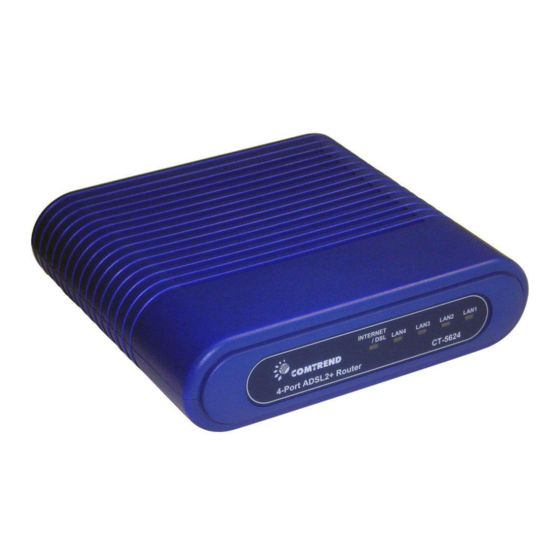
Chapter 2 Installation Front Panel The front panel contains lights called LEDs that indicate the status of the unit. Front Panel LEDs INTERNET/DSL Red: No ADSL link Orange on: The ADSL connection is established and the device had attempted to obtain an IP address but failed (reason: no DHCP response, no PPPoE response, PPPoE authentication failed, no IP address from IPCP, etc.) Red/Orange interlacing: the DSL is training. -
Page 7: Chapter 3 Connecting The Hardware
Step 5. Configure the Router with the Web User Interface (WUI). Chapters 5 through 9 show how to configure the CT-5624 to meet your needs. Step 6. Save the configurations and Reboot. To make the settings you configured on the router take effect. -
Page 8: Chapter 4 Login Via The Web Browser
The default IP address of the CT-5624 (LAN port) is 192.168.1.1. To configure the CT-5624 for the first time, the configuration PC must have a static IP address within the 192.168.1.x subnet. Follow the steps below to configure your PC IP address to use subnet 192.168.1.x. -
Page 9: Login Procedure
Perform the following steps to bring up the Web user interface and configure the CT-5624. To log on to the system from the Web browser, follow the steps below: STEP 1: Start your Internet browser. Type the IP address for the router in the Web address field. -
Page 10: Default Settings
4.3 Default Settings The following default settings are present when setting up the router for the first time. The PC running the browser can be attached to the Ethernet. • One PPPoE PVC (VPI=8, VCI=35) • NAT Enabled and Firewall Disabled •... -
Page 11: Chapter 5 Device Information
Chapter 5 Device Information The Summary screen appears as shown below. NOTE: The selections available on the main menu are based upon the configured connections and the active user account. -
Page 12: Wan
5.1 WAN This screen displays the configured PVC(s) and their status. VPI/VCI Shows the values of the ATM VPI/VCI Con. ID Shows the connection ID Category Shows the ATM service classes Service Shows the name for WAN connection Interface Shows connection interfaces Protocol Shows the connection type, such as PPPoE, PPPoA, etc. -
Page 13: Statistics
5.2 Statistics Selection of the Statistics screen provides statistics for the Network Interface of LAN, WAN, ATM and ADSL. All statistics screens are updated every 15 seconds. 5.2.1 LAN Statistics The Network Statistics screen shows interface statistics for the Ethernet interface. (The Network Statistics screen shows interface statistics for LAN of Ethernet interface. -
Page 14: Wan Statistics
5.2.2 WAN Statistics Service Shows the service type VPI/VCI Shows the values of the ATM VPI/VCI Protocol Shows the connection type, such as PPPoE, PPPoA, etc. Interface Shows connection interfaces Received/Transmitted - Bytes Rx/TX (receive/transmit) packet in Byte - Pkts Rx/TX (receive/transmit) packets - Errs Rx/TX (receive/transmit) packets with errors... -
Page 15: Atm Statistics
5.2.3 ATM statistics The following figure shows the ATM statistics screen. ATM Interface Statistics Field Description In Octets Number of received octets over the interface Out Octets Number of transmitted octets over the interface In Errors Number of cells dropped due to uncorrectable HEC errors In Unknown Number of received cells discarded during cell header validation, including cells with unrecognized VPI/VCI... - Page 16 Out Errors Number of received AAL5/AAL0 CPCS PDUs that could be transmitted due to errors. In Discards Number of received AAL5/AAL0 CPCS PDUs discarded due to an input buffer overflow condition. Out Discards This field is not currently used ATM AAL5 LAYER STATISTICS FOR EACH VCC OVER ADSL INTERFACE Field Descriptions CRC Errors...
-
Page 17: Adsl Statistics
5.2.4 ADSL Statistics The following figure shows the ADSL Network Statistics screen. Within the ADSL Statistics window, a bit Error Rate Test can be started using the ADSL BER Test button. The Reset button refreshes the ADSL statistics. - Page 18 Field Description Mode T1.413, G.lite, G.DMT, ADSL2/2+ or Re-ADSL Type Channel type Interleave or Fast Line Coding Line Coding format, that can be selected G.dmt, G.lite, T1.413, ADSL2, Annex L and Annex M Status Lists the status of the DSL link Link Power State Link output power state.
- Page 19 Within the ADSL Statistics window, a Bit Error Rate (BER) test can be started using the ADSL BER Test button. A small window will open when the button is pressed; it will appear as shown below. Click Start to start the test or Close. If the test is successful, the pop-up window will display as follows.
-
Page 20: Route
5.3 Route Choose Route to display the routes that the route information has learned. 5.4 ARP Click ARP to display the ARP information. -
Page 21: Dhcp
5.5 DHCP Click DHCP to display the DHCP information. -
Page 22: Chapter 6 Quick Setup
If the service provider provides PPPoE service, then the connection selection depends on whether the LAN-side device (typically a PC) is running a PPPoE client or whether the CT-5624 is to run the PPPoE client. The CT-5624 can support both cases simultaneously. -
Page 23: Auto Quick Setup
6.1 Auto Quick Setup The auto quick setup requires the ADSL link to be up. The ADSL router will automatically detect the PVC. You only need to follow the online instructions that you are prompted. 1. Select Quick Setup to display the DSL Quick Setup screen. 2. -
Page 24: Manual Quick Setup
6.2 Manual Quick Setup STEP 1: Click Quick Setup and un-tick the DSL Auto-connect checkbox to enable manual configuration of the connection type. Un-tick this checkbox to enable manual setup and display the following screen. STEP 2: Enter the Virtual Path Identifier (VPI) and Virtual Channel Identifier (VCI). -
Page 25: Ppp Over Atm (Pppoa) And Ppp Over Ethernet (Pppoe)
Bridging- LLC/SNAP-BRIDGING, VC/MUX Disconnect if no activity The CT-5624 can be configured to disconnect if there is no activity for a period of time by selecting the Dial on demand check box. When the checkbox is ticked, you need to enter the inactivity timeout period. The timeout period ranges from... - Page 26 PPP IP Extension The PPP IP Extension is a special feature deployed by some service providers. Unless your service provider specially requires this setup, do not select it. The PPP IP Extension supports the following conditions: • Allows only one PC on the LAN •...
- Page 27 Enable WAN Service checkbox: Tick this item to enable the ATM service. Untick it to stop the ATM service. Service Name: This is user-defined. 3. After entering your settings, select Next. The following screen appears. This page allows the user to configure the LAN interface IP address, subnet mask and DHCP server.
- Page 28 4. Click Next to display the WAN Setup-Summary screen that presents the entire configuration summary. Click Save/Reboot if the settings are correct. Click Back if you wish to modify the settings.
-
Page 29: Mac Encapsulation Routing (Mer)
The Web UI will not respond until the system is brought up again. After the system is up, the Web UI will refresh to the Device Info page automatically. The CT-5624 is ready for operation and the LEDs display as described in the LED description tables. - Page 30 4. Click Next to display the following screen. Enable NAT checkbox: If the LAN is configured with a private IP address, the user should select this checkbox. The NAT submenu on the left side main panel will be displayed after reboot. The user can then configure NAT-related features after the system comes up.
- Page 31 5. Upon completion, click Next. The following screen appears. The Device Setup page allows the user to configure the LAN interface IP address and DHCP server. If the user would like this ADSL router to assign dynamic IP addresses, DNS server and default gateway to other LAN devices, select the radio box Enable DHCP server and enter the Start and End IP address and the DHCP Leased Time.
-
Page 32: Ip Over Atm
The Web UI will not respond until the system is brought up again. After the system is up, the Web UI will refresh to the Device Info page automatically. The CT-5624 is ready for operation and the LEDs display as described in the LED description tables. - Page 33 NOTE: DHCP is not supported over IPoA. The user must enter the IP address or WAN interface for the default gateway setup, and the DNS server addresses provided by the ISP. 5. Click Next. The following screen appears. Enable NAT checkbox If the LAN is configured with a private IP address, the user should select this checkbox.
- Page 34 The user must configure the IP Address and the Subnet Mask. To use the DHCP service on the LAN, select the Enable DHCP server checkbox, and enter the Start IP addresses, the End IP address and DHCP lease time. This configures the router to automatically assign IP addresses, default gateway address and DNS server addresses to each of your PCs.
-
Page 35: Bridging
The Web UI will not respond until the system is brought up again. After the system is up, the Web UI will refresh to the Device Info page automatically. The CT-5624 is ready for operation and the LEDs display as described in the LED description tables. - Page 36 5. Click the Next button to continue. Enter the IP address for the LAN interface. The default IP address is 192.168.1.1. The LAN IP interface in bridge operating mode is needed for local users to manage the ADSL router. Notice that there is no IP address for the WAN interface in bridge mode, and the remote technical support cannot access the ADSL router.
- Page 37 6. The following screen will be displayed. The WAN Setup-Summary screen presents the entire configuration summary. Click Save/Reboot if the settings are correct. Click Back if you wish to modify the settings.
-
Page 38: Chapter 7 Advanced Setup
Chapter 7 Advanced Setup This chapter includes the following sections: WAN, LAN, NAT, Security, QoS, Routing, DNS, DSL, and Port Mapping 7.1 WAN This screen shows the default WAN interface. Users can choose to Add, Edit, or Remove these WAN interfaces. The Save/Reboot button saves the current configuration and reboots the router. -
Page 39: Lan
7.2 LAN Configure the DSL Router IP Address and Subnet Mask for LAN interface. Save button only saves the LAN configuration data. Save/Reboot button saves the LAN configuration data and reboots the router to make the new configuration effective. IP Address: Enter the IP address for the LAN port. Subnet Mask: Enter the subnet mask for the LAN port. -
Page 40: Nat
Configure the second IP address by ticking the checkbox shown below. IP Address: Enter the secondary IP address for the LAN port. Subnet Mask: Enter the secondary subnet mask for the LAN port. NOTE: The Save button saves new settings to allow continued configuration while the Save/Reboot button not only saves new settings but also reboots the device to apply the new configuration (i.e. - Page 41 To add a Virtual Server, click the Add button. The following will be displayed. Select a Service User should select the service from the list. Custom Server User can enter the name of their choice. Server IP Address Enter the IP address for the server. External Port Enter the starting external port number (when you select Start...
-
Page 42: Port Triggering
7.3.2 Port Triggering Some applications require that specific ports in the Router's firewall be opened for access by the remote parties. Port Trigger dynamically opens up the 'Open Ports' in the firewall when an application on the LAN initiates a TCP/UDP connection to a remote party using the 'Triggering Ports'. -
Page 43: Dmz Host
7.3.3 DMZ Host The DSL router will forward IP packets from the WAN that do not belong to any of the applications configured in the Virtual Servers table to the DMZ host computer. Enter the computer's IP address and click "Apply" to activate the DMZ host. Clear the IP address field and click "Apply"... -
Page 44: Security
7.4 Security To display the Security function, you must enable the firewall in WAN Setup. 7.4.1 IP Filtering IP filtering allows you to create a filter rule to identify outgoing/incoming IP traffic by specifying a new filter name and at least one condition below. All of the specified conditions in this filter rule must be satisfied for the rule to take effect. - Page 45 Filter Name Type a name for the filter rule. Protocol User can select from: TCP, TCP/UDP, UDP or ICMP. Source IP address Enter source IP address. Source Subnet Mask Enter source subnet mask. Source Port (port or port:port) Enter source port number. Destination IP address Enter destination IP address.
-
Page 46: Mac Filter
Each network device has a unique 48-bit MAC address. This can be used to filter (block or forward) packets based on the originating device. MAC filtering policy and rules for the CT-5624 can be set according to the following procedure. The policy FORWARDED means that all MAC layer frames will be FORWARDED except those matching the rules specified in the following table. - Page 47 Choose Add or Remove to configure MAC filtering rules. The following screen will appear when you click Add. Create a filter to identify the MAC layer frames by specifying at least one condition below. If multiple conditions are specified, all of them must be met. Click Save/Apply to save and activate the filter rule. Field Description Protocol Type...
-
Page 48: Quality Of Service
7.5 Quality of Service To display this function, you must enable QoS in WAN Setup. Choose Add to configure network traffic classes. The following screen will be displayed:... - Page 49 The screen creates a traffic class rule to classify the upstream traffic, assign queuing priority and optionally overwrite the IP header TOS byte. A rule consists of a class name and at least one condition below. All of the specified conditions in this classification rule must be satisfied for the rule to take effect.
-
Page 50: Routing
Destination Subnet Mask Enter destination subnet mask. Destination port (port or Enter destination port number. port:port) SET-2 802.1p Priority Select between 0-7. Traffic Class Name Enter name for traffic class Priority Select Low, Medium or High. IP Precedence Select between 0-7. The lower the digit shows the higher the priority IP Type Of Service Select either: Normal Service, Minimize Cost,... -
Page 51: Static Route
7.6.2 Static Route Choose Static Route to display the Static Route screen. The Static Route screen lists the configured static routes, and allows configuring static routes. Choose Add or Remove to configure the static routes. To add static route, click the Add button to display the following screen. Enter the destination network address, subnet mask, gateway and available WAN interface then click Save/Apply to add the entry to the routing table. -
Page 52: Rip
7.6.3 To activate RIP for the device, select the 'Enabled' radio button for Global RIP Mode. To configure an individual interface, select the desired RIP version and operation, followed by placing a check in the 'Enabled' checkbox for the interface. Click the 'Save/Apply' button to save the configuration, and to start or stop RIP based on the Global RIP mode selected. -
Page 53: Dns
7.7 DNS 7.7.1 DNS Server If 'Enable Automatic Assigned DNS' checkbox is selected, this router will accept the first received DNS assignment from one of the PPPoA, PPPoE or MER/DHCP enabled PVC(s) during the connection establishment. If the checkbox is not selected, enter the primary and optional secondary DNS server IP addresses. - Page 54 NOTE: The Add/Remove buttons will only be displayed if the CPE has already been assigned an IP address from the remote server. To add a dynamic DNS service, simply click the Add button. The following screen will be displayed: D-DNS provider Select a dynamic DNS provider from the list.
-
Page 55: Dsl
7.8 DSL To access the DSL settings, first click On Advanced Setup and then click on DSL. The DSL Settings dialog box allows you to select an appropriate modulation mode. Option Description G.dmt Enabled Sets G.Dmt if you want the system to use G.Dmt mode. G.Lite Enabled Sets G.Lite if you want the system to use G.Lite mode. -
Page 56: Port Mapping
7.9 Port Mapping Port Mapping supports multiple ports to PVC and bridging groups. Each group will perform as an independent network. To support this feature, you must create mapping groups with appropriate LAN and WAN interfaces using the Add button. The Remove button will remove the grouping and add the ungrouped interfaces to the Default group. - Page 57 To create a group from the list, first enter the group name and then select from the available interfaces on the list. Automatically Add Clients With the Following DHCP Vendor IDs: Add support to automatically map LAN interfaces to PVC's using DHCP vendor ID (option 60).
-
Page 58: Ping
In the LAN side, PC can get IP address from CPE's dhcp server and access Internet via PPPoE (0/33). If the setup-box was connected with interface "ENET1" and send a dhcp request with vendor id "Video", CPE's dhcp server will forward this request to ISP's dhcp server. -
Page 59: Traceroute
7.11 TraceRoute This screen performs the same function as the console command of the same name. It allows you to trace the path between the router and any location on the LAN or WAN within 30 hops of the router. Enter the IP address of the location you wish to trace and click TraceRoute. -
Page 60: Chapter 8 Diagnostics
Chapter 8 Diagnostics The Diagnostics menu provides feedback on the connection status of the CT-5624 and the ADSL link. The individual tests are listed below. If a test displays a fail status, click Rerun Diagnostic Tests at the bottom of this page to make sure the fail status is consistent. - Page 61 In router modes, such as PPPoE, this screen will also include ISP tests as shown. ISP Connection Pass: Indicates that the router can access the ISP Default Gateway or Domain Name Server (DNS). Fail: Indicates that the router cannot access the ISP Default Gateway or Domain Name Server (DNS).
-
Page 62: Chapter 9 Management
The system administrator can do the following functions to manage the configurations, events, SNMP information, user accounts, and software update of the CT-5624. 9.1 Settings The Settings option allows you to back up your settings to a file and retrieve the file settings. -
Page 63: Update Settings
9.1.2 Update Settings This option under Management>Settings updates your router settings using your saved files. -
Page 64: Restore Default
NOTE: This entry has the same effect as the hardware reset-to-default button. The CT-5624 board hardware and the boot loader support the reset to default button. If the reset button is continuously pushed for more than 5 seconds, the boot loader will erase the entire configuration data saved on the flash memory. -
Page 65: System Log
9.2 System Log The System Log option under Management>Settings allows you to view the system events log, or to configure the System Log options. The default setting of system log is disabled. Follow the steps below to enable and view the system log. - Page 66 “Emergency” down to this configured level will be recorded to the log buffer on the CT-5624 SDRAM. When the log buffer is full, the newer event will wrap up to the top of the log buffer and overwrite the old event.
-
Page 67: Snmp Agent
9.3 SNMP Agent Simple Network Management Protocol (SNMP) allows a management application to retrieve statistics and status from the SNMP agent in this device. Select desired settings and click Save/Apply to apply changes. Enable or Disable the SNMP Agent. Relationship between an Agent and Managers Read Default is “public”... -
Page 68: Internet Time
9.4 Internet Time The Internet Time option under Management menu bar configures the Modem’s time. To automatically synchronize with Internet time servers, tick the corresponding box displayed on the screen. Then click Save/Apply. -
Page 69: Access Control
9.5 Access Control The Access Control option under Management menu bar configures the access-related parameters, including three parts: Services, IP Address, and Passwords. 9.5.1 Services The Services option limits or opens the access services over the LAN or WAN. These services are provided FTP, HTTP, ICMP, SNMP, TELNET, and TFTP. The “Services”... -
Page 70: Ip Addresses
9.5.2 IP Addresses The IP Addresses option limits the access by IP address. If the Access Control Mode is enabled, only the allowed IP addresses can access the router. Before you enable it, configure the IP addresses by clicking the Add button. Enter the IP address and click Apply to allow the PC with this IP address to manage the router. -
Page 71: Passwords
9.5.3 Passwords The Passwords option configures the access passwords for the router. Access to your DSL router is controlled through the following user accounts: • root has unrestricted access to change and view the configuration • support is used for remote maintenance and diagnostics. •... -
Page 72: Update Software
9.6 Update software The Update Software screen allows you to obtain an updated software image file from your ISP. Manual software upgrades from a locally stored file can be performed using the following screen. Step 1: Obtain an updated software image file from your ISP. Step 2: Enter the path to the image file location in the box below or click the Browse button to locate the image file. -
Page 73: Save And Reboot
9.7 Save and Reboot The Save/Reboot options saving the configurations and reboot the router. Close the DSL Router Configuration window and wait for 2 minutes before reopening your web browser. If necessary, reconfigure your PC's IP address to match your new configuration. -
Page 74: Appendix A: Firewall
Appendix A: Firewall Stateful Packet Inspection Refers to an architecture, where the firewall keeps track of packets on each connection traversing all its interfaces and makes sure they are valid. This is in contrast to static packet filtering which only examines a packet based on the information in the packet header. - Page 75 This filter will Drop all TCP packets coming from LAN with IP Address/Sub. Mask 192.168.1.45/24 having a source port of 80 irrespective of the destination. All other packets will be Accepted. Filter Name : Out_Filter2 Protocol : UDP Source Address : 192.168.1.45 Source Subnet Mask : 255.255.255.0...
- Page 76 mer_0_35/nas_0_35 with IP Address/Sub. Mask 210.168.219.45/16 having a source port of 80 irrespective of the destination. All other incoming packets on this interface are DROPPED. Filter Name : In_Filter2 Protocol : UDP Source Address : 210.168.219.45 Source Subnet Mask : 255.255.0.0 Source Port : 5060:6060 Dest.
- Page 77 Example 1: Global Policy: Forwarded Protocol Type: PPPoE Dest. MAC Addr: 00:12:34:56:78 Source MAC Addr: Null Frame Direction: LAN => WAN WAN Interface Selected: br_0_34/nas_0_34 Addition of this rule drops all PPPoE frames going from LAN-side to WAN-side with a Dest. MAC Addr. of 00:12:34:56:78 irrespective of its Source MAC Addr. on the br_0_34 WAN interface.
-
Page 78: Appendix B: Pin Assignments
Appendix B: Pin Assignments Line Port (RJ11) Definition Definition ADSL_TIP ADSL_RING LAN Port (RJ45) Definition Definition Transmit data+ Transmit data- Receive data- Receive data+... -
Page 79: Appendix C: Specifications
Appendix C: Specifications Rear Panel RJ-11 X1 for ADSL, RJ-45 X 4 for LAN, Power Button X 1, Reset Button X 1 ADSL ITU-T G.992.5, ITU-T G.992.3, ITU-T G.992.1, ANSI T1.413 Issue 2 G.992.5 (ADSL2+) Downstream : 24 Mbps Upstream : 1.3 Mbps G.992.3 (ADSL2) Downstream : 12 Mbps Upstream : 1.3 Mbps G.DMT Downstream : 8 Mbps Upstream : 832 Kbps... - Page 80 Power Supply External power adapter 110 Vac or 220 Vac Environment Condition Operating temperature 0 ~ 50 degrees Celsius Relative humidity 5 ~ 90% (non-condensing) Dimensions 140 mm (W) x 40 mm (H) x 133 mm (D) NOTE: Specifications are subject to change without notice...
Need help?
Do you have a question about the CT-5624 and is the answer not in the manual?
Questions and answers