Table of Contents
Advertisement
Quick Links
Advertisement
Table of Contents

Related Manuals for Comtrend Corporation CT-5241


Summary of Contents for Comtrend Corporation CT-5241
- Page 1 CT-5241 SHDSL Router User’s Manual Version A1.0, January 16, 2007 261039-013...
- Page 2 Preface This manual is designed to provide information to network administrators. It covers the installation, operation and applications of the CT-5241 SHDSL router. The reader reading this manual is presumed to have a basic understanding of telecommunications. For product update, new product release, manual revision, software upgrade, technical support, etc., visit Comtrend Corporation at...
-
Page 3: Table Of Contents
CHAPTER 1 OVERVIEW......................6 ..........................6 PPLICATION ..........................7 EATURES LED I ........................8 NDICATORS CHAPTER 2 INSTALLATION......................9 2.1 H .......................9 ARDWARE NSTALLATION 2.2 R ....................10 PANEL ONNECTIONS CHAPTER 3 QUICK INSTALLATION..................11 3.1 L .............................11 OGIN 3.1.1 Web Page Layout ......................13 3.1.2 Monitoring the SHDSL Line ..................14 WAN I ..................15 NTERFACE... - Page 4 LAN I ........................31 NTERFACE WAN I ...................32 ONFIGURING THE NTERFACE 4.2.1 VC Data Flow Control....................32 4.2.2 Setting up an ISP ......................34 CHAPTER 5 SNMP ........................35 SNMP ........................35 NABLE SNMP ........................36 ISABLE CHAPTER 6 PACKET FILTER ....................37 ....................37 DD A ACKET ILTER ENTRY ..................39 ELETE A...
- Page 5 CHAPTER 12 VLAN ........................56 CHAPTER 13 MAINTENANCE AND DIAGNOSTICS ............57 13.1 .........57 OFTWARE PGRADE AND ONFIGURATION ACKUP ESTORATION 13.2 OAM L .......................61 OOPBACK 13.3 ...........................62 13.4 .....................63 ERFORMANCE ONITORING CHAPTER 14 APPLICATION EXAMPLE ................66 14.1 ) ..................66 DDING THE TATIC OUTE CHAPTER 15 PIN ASSIGNMENTS ..................68...
-
Page 6: Chapter 1 Overview
Chapter 1 Overview The SHDSL router satisfies the needs of multiple users in small/home offices and remote/branch offices. It provides symmetrical transmission speeds of up to 4.6 Mbps through a SHDSL connection, over a four-wire line. In addition, it supports up to 16 virtual concurrent connections to multiple destinations. -
Page 7: Features
Features Compliant with ITU-T G.991.2 (G.SHDSL) and G.994.1 (G.hs) 2-wire operation with auto-detection or manual setting 4-port 10/100 Base-T Ethernet switch with MDI/MDIX Operates as a Bridge & Router RFC 2684 (1483) Bridging RFC 2684 (1483) Routing RFC 2364 PPPoA RFC 2516 PPPoE OAM F4/F5 Supports up to 16 VCs... -
Page 8: Led Indicators
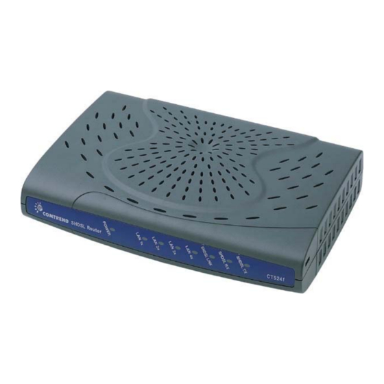
Web browser configuration and management tool LED Indicators There are eight LEDs on the front panel of the router; the functions of the LEDs are described in the table below. Color Mode Function POWER Green Power is supplied. Power is not supplied. LAN 1~4 Green An Ethernet link is established. -
Page 9: Chapter 2 Installation
Chapter 2 Installation 2.1 Hardware Installation The following equipment may be necessary to install the router: AC power adapter A power adapter is shipped with the router. LAN connection cable To connect to the hub, use a straight-through RJ45 cable. To connect to a PC, use a crossover RJ45 cable. -
Page 10: 2.2 Rear-Panel Connections
2.2 Rear-panel Connections Step 1 DSL connection Connect the supplied RJ-45 cable to the port marked LINE at the back of the SHDSL router. Connect the other end of the cable to your telephone-line wall outlet. Ensure your computer is turned on before you connect the DSL line to the router. -
Page 11: Chapter 3 Quick Installation
Chapter 3 Quick Installation This section describes how to manage the router via the Web browser from the remote end. The Web page is best read with a display resolution of 1024 x 768. To change the resolution you can go to the Microsoft Windows control panel and click on the Display icon, and change the display settings. - Page 12 STEP 3: Enter the IP address of the router in the Web address field. For example, if the IP address is 192.168.1.1, enter http:// 192.168.1.1 STEP 4: You will be prompted to enter your user name and password. Type your password, or if the password was not changed, type the default passwords.
-
Page 13: Web
3.1.1 Web Page Layout On each Web page, there are two areas. Menu Bar: On the left side of the Web page is the menu bar. It is divided into two parts: Basic and Advanced. The Basic menu bar sets up the device for quick setup. -
Page 14: Monitoring The Shdsl Line
3.1.2 Monitoring the SHDSL Line Click Link Status on the Basic menu bar. The Link Status screen has two tabs: SHDSL Status and Performance. SHDSL Status is used to monitor the SHDSL link and the Performance is used to monitor the SHDSL performance. The following is the screen after clicking the [Performance] button. -
Page 15: Wan Interface Configuration
WAN Interface Configuration The router supports 16 ATM interfaces. A virtual channel (VC) can be configured for each ATM interface such as ATM1 to VC1, ATM 2 to VC2…. Each VC can be specified with a protocol, which can be RFC-1483 bridged, RFC-1483 Routed, PPPoE or PPPoA. -
Page 16: Bridge Mode: Service For One Fixed Ip Address
3.2.1 Bridge mode: Service for one fixed IP address To configure one static IP address, you need to set-up the VC in RFC1483 bridged mode. The router has a default Virtual Channel (VC) of 0/33. It can function without other modifications. STEP 1: Click WAN Setup on the Basic menu bar, and enter values for: VPI, VCI, Encapsulation (LLC or VC MUX). - Page 17 To modify the VC, select (click) a VC from the Current ATM PVC List to display the parameters of the VC. Change its parameters and click the Modify button.
-
Page 18: Router Mode: Service For Five Static Ip Addresses
3.2.2 Router Mode: Service for Five Static IP Addresses To set-up the service for five static IP addresses, you need to set-up the VC in RFC1483 Routed mode. STEP 1: Click WAN Setup on the Basic menu bar. STEP 2: Enter values for: VPI, VCI, Encapsulation (LLC or VC MUX), Enable NAPT. Enter a value for the virtual path identifier. - Page 19 STEP 4: Click the Add button. The new VC is added in the Current ATM PVC List on the bottom screen. To modify the VC, click a VC from the Current ATM PVC List to display the parameters of the VC. Change its parameters and click the Modify button.
- Page 20 After creating an RFC1483 Routed VC, click LAN Setup to set-up the router’s Ethernet IP address. After changing the IP address, click Apply to display the following screen. The Change & Reboot button allows you to use the new IP address and reboot the router immediately.
- Page 21 STEP1: Click WAN Setup on the Basic menu bar. STEP2: select 0/34 from the Current ATM PVC List to display the parameters and click RFC 1483 Routed and then click the Modify button. STEP 3: Click LAN Setup on the menu bar to type the IP address for the LAN port.
-
Page 22: Pppoe
3.2.3 PPPoE When a VC is set in the PPPoE, the router will auto-detect the Authentication code (PAP or CHAP). The NAPT and DHCP server functions will be enabled automatically. STEP 1: Click WAN Setup on the Basic menu bar and enter the following parameters to set-up the PPPoE. - Page 23 Mode Direct and Auto. If the mode is set to Auto, the PPPoE negotiation automatically starts when the system identifies any traffic required to be transferred on the link. When DIRECT is selected the PPPoE negotiation is started manually. Idle Timeout The Idle Time field defines the period of idle time after which the PPPoE link will be terminated.
-
Page 24: Pppoa
3.2.4 PPPoA When a VC is configured for PPPoA, the router will auto-detect the Authentication code (PAP or CHAP), and the NAPT function will be enabled automatically. STEP 1: Click WAN Setup on the Basic menu bar. STEP 2: Enter values for the following fields: VPI, VCI, Encapsulation (LLC or VC MUX), Enable NAPT. -
Page 25: Password Setup
3.2.5 Password Setup There are two types of access privileges. A system ADMINISTRATOR is the only person that can configure, change parameters, monitor, and read the performance and status of the system. A USER can only monitor and read the status of the system. - Page 26 Terminal Type: When the router is connected to the DSLAM, select CPE. When the router is connect to a router for point to point application, one of the devices should be set to CO with the other set to CPE. The default setting is CPE.
-
Page 27: Setting The Bridge
3.2.6 Setting the Bridge Click Bridging on the Advanced menu bar to set-up the static bridging and Spanning Tree protocol (STP) functions. Spanning Tree Protocol The STP function is disabled by factory default. To enable it, click Enable in the Spanning Tree field and configure the interfaces on the screen. -
Page 28: Static Bridging
Static Bridging Click the Static tab to configure, modify, or delete the static bridging functions. Add a static bridging entry Delete Delete a static bridging entry List Displays all the static bridging entries Flush Delete all the static bridging entries MAC Address: This is the Mac address of the Pc or the remote MAC address of the ISP. -
Page 29: Write System Configurations
3.4.1 Write System Configurations The new parameters can function immediately without being saved to the flash memory. To use these parameters after you restart the router, you must save them to the flash memory. To write the configurations, click the Save & Reboot button. Click the Save button on the main screen. -
Page 30: Load Factory Default Values
3.4.2 Load Factory Default Values Caution! If you reset your device to the factory default, any changes to parameters will be lost and all parameters will revert to their default values. To retrieve the factory default settings, STEP 1: Click Erase & Reboot on the Basic menu bar. STEP 2: Click Erase and Reboot respectively. -
Page 31: Chapter 4 Setting Up Wan And Lan Interfaces
Chapter 4 Setting up WAN and LAN Interfaces LAN Interface To set-up the Ethernet Interface, follow the descriptions below: STEP 1: Click LAN Setup on the Basic Menu bar. STEP 2: Enter the new IP address and Subnet, and click Apply to display the following screen. -
Page 32: Configuring The Wan Interface
Configuring the WAN Interface Click WAN Setup on the Basic menu bar and configure the VC to RFC1483 Bridged, RFC1483 Routed, PPPoE or PPPoA. To set up these services, refer to Section 3.2. 4.2.1 VC Data Flow Control To set-up the flow control parameters, such as AAL5 encapsulation, QOS, Peak Cell Rate, Sustainable Cell Rate, and Burst Tolerance, follow the steps below. - Page 33 Tick a VC in the Index field and click the modify button to configure the VC’s flow control parameters. Click OK to complete the settings.
-
Page 34: Setting Up An Isp
4.2.2 Setting up an ISP The router supports connection to up to 16 ISPs. Each ATM Interface can connect to an ISP. To set-up or configure the connection parameters to ISP, click WAN Configure on the Advanced menu bar. Click the ISP tab on the main screen. -
Page 35: Chapter 5 Snmp
Chapter 5 SNMP The default setting of the SNMP function is enabled. SNMP is a software entity that responds to information and action request messages sent by a network management station. The messages exchanged enable you to access and manage objects in an active or inactive (stored) MIB on a particular router. -
Page 36: Disable Snmp
Disable SNMP Click SNMP on the Advanced menu bar and click the Modify button at the bottom of the screen. Choose Disable in the SNMP Service field and click Apply to submit the setting. -
Page 37: Chapter 6 Packet Filter
(IP address, port number, etc.) of the network and determines whether to forward the packets or not, based on user-defined rules (deny, accept and count). The CT-5241 SHDSL router provides packet filter and stateful packet inspection. It has denial of service protection against attacks such as ICMP Flood, Ping of Death, IP spoofing, Port Scans, Land Attacks, Tear Drop Attacks, IP Source Route and WinNuke Attacks. - Page 38 Protocol Select from TCP/UDP/ICMP/IP Source IP Source IP of a packet you wish to filter Source Mask Source Mask of a packet Source Port Source Port of a packet you wish to filter Destination IP Destination IP of a packet you wish to filter Destination Mask Destination Mask of a packet Destination Port...
-
Page 39: Delete A Packet Filter Entry
Delete a Packet Filter entry To delete an entry, select an entry from the list, and click Delete. Enable/Disable Packet Filter If you wish to Enable/Disable Packet Filter, click Enable or Disable and click the Apply button. -
Page 40: Chapter 7 Routing
Chapter 7 Routing This chapter describes how to set-up the static routes and RIP. Click Routing Setup from the Basic menu bar to configure the routing functions. Static Route The Static Route Configuration field allows you to add, modify, and delete a static route. - Page 41 Add: To add a static route complete the following steps: STEP 1: Enter the parameters for Destination Network ID, Subnet Mask, Next Hop IP STEP 2: Click the ADD button Modify: To modify a static route complete the following steps: STEP 1: Select the entry you wish to modify from the List of Static Routes STEP 2: Change the parameters STEP 3: Click the Modify button...
-
Page 42: Set-Up The Rip Function
Set-up the RIP function To enable the RIP, complete the following steps: STEP 1: Click Routing Setup from the Basic menu bar STEP 2: Select Enable in the Rip Status field. STEP 3: Select a RIP Version (Version 1 or Version 2) from the Version field. STEP 4: Click Apply to submit the settings. - Page 43 Enter BASIC/ROUTING/RIP to configure the parameters.
-
Page 44: Displaying The Routing Table
Displaying the Routing Table To display the routing table, you can enter either of the following screens: BASIC/ROUTING SETUP/ ROUTING TABLE screen Advance/Utilities/Routing Table The following routing table appears after clicking Basic>Routing Setup>Routing Table. -
Page 45: Chapter 8 Nat
Chapter 8 Network Address Translation (NAT or NAPT) is a transparent routing function that translates a Private IP address on a LAN into a Public address that can be used in a public network. Port Address Translation (PAT) is a form of NAT that maps multiple Private IP addresses to a single Public IP address. -
Page 46: Multiple To One
In PPPoE or PPPoA mode, the NAT function is automatically enabled. In RFC1483 Routed mode, to enable the NAT, you must tick the Enable NAPT item on the WAN Setup screen. The following pages describe how to set-up a virtual server (Redirect port) and different types of NAT. -
Page 47: One To One Nat
One to One NAT One-to-one NAT maps a private IP address to a public IP address, such as 192.168.1.10 to 10.1.1.34. Click NAPT on the Advanced menu bar and click the NAT/PAT tab to access the NAT/PAT Configuration screen. Follow the steps below: STEP 1: Select Fixed-NAT. -
Page 48: Multi-Nat
Multi-NAT Multi-NAT maps a set of continuous private IP addresses to a set of continuous public IP addresses. There are two types of Multi-NAT to translate the private IP addresses to public IP addresses. One condition is that each public IP address can map an individual private IP address. - Page 49 STEP 2: Click the Add button. When the Local IP addresses are more than the public IP addresses This application can be used when the public IP addresses are not enough that each Local IP address can be mapped to each public IP address. The following parameters are used: Start Local IP address- End Local IP Address: 192.168.1.3- 192.168.1.22 Start Public IP Address- End Public IP Address: 10.1.1.3-10.1.1.10...
-
Page 50: Virtual Server
Virtual Server If you want to set-up Internet servers, such as Email server, web server, or ftp server on the virtual LAN when PAT is enabled, you should register the servers with the router first to allow Internet users to access the service via the WAN interface of router. -
Page 51: Chapter 9 Dhcp
Chapter 9 DHCP The router can be set as a DHCP server or a DHCP relay. The former acts like an IP address pool. Upon power on, the PCs on the same domain will request an available IP address from the IP address pool of the DHCP server. The Dynamic Host Configuration Protocol (DHCP) provides a centralized approach to allocating IP addresses. -
Page 52: Dhcp Relay
DHCP Relay Click DHCP on the Advanced menu bar. On the main screen, click the BOOTP/DHCP Relay tab and configure the following parameters: BOOTP/DHCP Relay: Enable IP Address: This defines the IP address of the remote DHCP server. After completing the settings, click Apply to submit the settings. Also, change the PCs LAN IP address. -
Page 53: Chapter 10 Dns Proxy
Chapter 10 DNS Proxy A Domain Name Server (DNS) provides an IP address to a host computer for an applied Domain Name. The router supports the DNS proxy feature, which receives and attempts to find an entry in its local tables, and when one is not found, it forwards the request to a remote server. -
Page 54: Chapter 11 Igmp
Chapter 11 IGMP IGMP (Internet Group Membership Protocol) is a protocol used by IP hosts to report their multicast group memberships to any immediately neighboring multicast routers. STEP 1: Add a VC and set it to RFC 1483 Routed mode. STEP 2: Click IGMP Proxy on the Advanced menu bar. - Page 55 STEP 3: Click Enable and choose the interface ATM1-ATM16 that the router is used to connect to the server. This depends on VC to which interface it is assigned. STEP 4: Click Apply to submit the settings.
-
Page 56: Chapter 12 Vlan
Chapter 12 VLAN To configure the VLAN function, click VLAN from the Advanced menu bar. VLAN is disabled by factory default. To enable it, tick Enable and click the Set button. Then you can proceed to create the VLAN groups. The STU-R supports four VLAN groups, VLAN groups 1 to 4. -
Page 57: Chapter 13 Maintenance And Diagnostics
Chapter 13 Maintenance and Diagnostics This chapter describes the maintenance functions such as loopback, PING, software upgrade via TFTP, configuration backup and restoration, and performance monitoring. 13.1 Software Upgrade and Configuration Backup /Restoration The router supports TFTP upgrade via Console, Telnet, and Web browser. Via a TFTP server, these tasks can be achieved: upgrade the software, back up the configuration, and retrieve the configurations. - Page 58 Note2: If a wrong format of the file is inputted, a failure message will display during the upgrade. The following is an example of upgrade failure resulting from an incorrect file format.
- Page 59 Before performing the TFTP upgrade, run the TFTP software. Click Utilities on the Advanced menu bar. Fill out the TFTP Server IP address, file name, and upgrade type. Software upgrade: Check Download and choose Firmware in the column to the right. Homepage upgrade: Check Download and choose Homepage in the column to the right.
- Page 60 The following is an example of how to set-up the parameters for homepage upgrade. To upload the configurations, check Upload, select Configuration, and click the Apply button to submit the settings.
-
Page 61: Oam Loopback
13.2 OAM Loopback Click Utilities on the Advanced menu bar, and click the Loopback tab on the main screen. After filling out the following parameters, click Start Loopback to perform the loopback. Flow Type Choose the F5 loopback type. Seg is the segment loopback. It verifies the connection between the router and DSLAM. -
Page 62: Ping
13.3 Ping A Ping test is used to verify the status of a network connection after the RIP or static route function is enabled. Ping sends a request message to the host and waits for a return message. This diagnostic function can verify if the remote host is reachable. -
Page 63: Performance Monitoring
13.4 Performance Monitoring System statistics Click System Statistics on the Advanced menu bar to monitor the interface status and collect the statistics of the TCP/IP. - Page 64 To display the interface statistics, click the Interface tab, located at the top-left of the System Statistics screen. The Interface Statistics page displays statistics for all interfaces. The following information is displayed: The name of the interface Admin Status Indicates whether the interface is Up or Down In Octets The number of Octets (bytes) received InUncastPkts...
- Page 65 To view TCP-IP statistics click on the TCP-IP tab at the top of the System Statistics page. The TCP-IP page displays the IP statistics, UDP statistics, TCP statistics, and ICMP statistics. Interface Click Interface Monitor on the Advanced menu bar to monitor the transmission status.
-
Page 66: Chapter 14 Application Example
Chapter 14 Application Example 14.1 Adding the Static Route (Web) Click Routing Setup on the Basic menu bar. The following demonstrates a school application as an example. Location A:10.164.32.9 Netmask:255.255.255.252 Location B:10.164.32.10 Netmask:255.255.255.252 Network of the School :210.240.117.0 Netmask:255.255.255.128 In the above example, add the following static route to the router. Network ID192.168.1.155 Netmask:255.255.255.128 Next hop: 10.164.32.9 Enter the parameters of the static route and click the Add button. - Page 67 Click LAN Setup on the Basic menu bar. After typing LAN IP 10.164.32.10 and Netmask 255.255.255.252, click Apply to submit the settings.
-
Page 68: Chapter 15 Pin Assignments
Chapter 15 Pin Assignments Console Port (RS232 DB9) Pin number Definition Pin number Definition LAN Port (RJ45) Pin number Definition Pin number Definition LINE Port (RJ11) Pin number Definition Pin number Definition Loop2-1 Loop1-2 Loop2-2 Loop1-1... -
Page 69: Chapter 16 Console Access
Chapter 16 Console Access To access the device via the console port the following are required: VT-100 Compatible Terminal This terminal is essential to perform the initial configuration of the router. This is normally a terminal with a VT-100 emulation program, such as Telix or HyperTerminal Edition 5. - Page 70 STEP4: After successfully logging in, the main menu will display.
-
Page 71: Keyboard Operations
16.2 Keyboard Operations ↑ HE UPWARD ARROW KEY MOVES THE CURSOR UPWARD IN THE MENU ↓ The cursor moves downward in the menu. ← Returns to the previous menu. If you are in a leaf menu you may need to push first (to save the information) →... - Page 72 If you are unable to use the arrow keys, you can use the backup keys to replace them, e.g., Ctrl-W for the Up arrow key. These backup keys also display on the bottom screen. In addition to the arrow keys to move the cursor in the menu, you enter the requested screen by entering the number.
- Page 73 STEP 2: From the MAIN/ADVANCE menu, press the 2 key and then press the Enter key STEP 3: Press the 2 key, and then press the Enter key in MAIN/ADVANCE/DHCP. STEP 4: Now you have reached MAIN/ADVANCE/DHCP/RELAY.
-
Page 74: Monitoring The Shdsl Line Status
16.3 Monitoring the SHDSL Line Status Enter MAIN/BASIC/SHDSL to monitor the SHDSL Line status. 16.4 Password Setup Enter MAIN/BASIC/SYSTEM to change the passwords. -
Page 75: Retrieve The Factory Default Settings
New Administrator Password and Retype Password: Enter the administrator password in the New Administrator Password and confirm the password by retyping the password in the Retype Password field. New User Password and Retype Password: Enter the user password in the New User Password and confirm the password by retyping the password in the Retype Password field. -
Page 76: Save The Configurations
16.7 Save the Configurations The new parameters can function immediately without being saved to the flash memory. However, to use these parameters after you restart the router, you must save them to the flash memory. To write the configurations, enter MAIN/WRITE and press the Y key. After saving the configurations, you will be prompted if you need to reboot the device. -
Page 77: Chapter 17 Telnet Access
Chapter 17 Telnet Access STEP 1: Configure your workstation to the same network segment as the router, such as IP address 192.168.1.133 and subnet mask 255.255.255.0. STEP 2: Click [Start]> [run], type telnet 192.168.1.1 and click OK. (192.168.1.1 is the default IP address. If it was changed, use the new IP address to login.) - Page 78 STEP 3: Enter the user name and password and press Enter to login (The default password and user name are root) STEP 4: The following displays the main menu after login.
-
Page 79: Appendix A: Specifications
Appendix A: Specifications WAN Interface (One SHDSL port) SHDSL standard ITU-T G991.2 / G994.1 SHDSL Line Interface RJ-45 Encoding scheme TC-PAM Line rate Per ITU-T G991.2 (SHDSL) Data rate N X 2 x 64 Kbps (4 wire) or N x 64 Kbps (2 wire) , N=3~36, Encapsulation Multi-protocol over AAL5 Bridged RFC-2684 (1483) - Page 80 Routing functions NAT/PAT IP static route RIP and RIPv2 IGMP Proxy VLAN Security functions Mac Filtering Packet filtering VPN Pass Through Network functions DNS, NAT/PAT, DHCP/BOOTP PAP, CHAP Power Supply External power adapter 110VAC or 220 VAC Frequency 50/60 Hz Environmental Conditions Operating temperature 0〜50 degrees Celsius...
Need help?
Do you have a question about the CT-5241 and is the answer not in the manual?
Questions and answers