DoorKing 9000 Series Installation & Owner's Manual
Vehicular slide
Hide thumbs
Also See for 9000 Series:
- Quick start manual (2 pages) ,
- Manual (5 pages) ,
- Quick start manual (2 pages)
Table of Contents
Advertisement
Quick Links
Installation/Owner's Manual
Use this manual for circuit board 4405-018 Revision A or higher.
Entrapment Protection must be provided for the gate system where the risk of entrapment or obstruction exists. The operator
will NOT run without one or more monitored type B1 or B2 entrapment protection devices in EACH direction of gate travel.
UL 325 August 2018 Standard
THIS PRODUCT IS TO BE INSTALLED AND SERVICED BY A TRAINED GATE/DOOR SYSTEMS TECHNICIAN ONLY.
Visit www.doorking.com/dealer-locator to find a professional installing and servicing dealer in your area.
Date Installed:
Installer/Company Name:
Phone Number:
Leave manual with owner : Property owner checklist in back of manual for new installation verification
Conforms To UL STD 325
Certified To CSA STD C22.2 # 247
Circuit Board
Serial Number
and Revision Letter:
Copyright 2020 DoorKing
®
, Inc. All rights reserved.
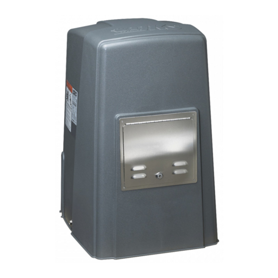
Series 9000
Series 9000
Series 9000
Vehicular Slide Gate Operator
Copyright 2009 DoorKing, Inc. All rights reserved.
9000-065-F-2-20
Advertisement
Table of Contents
Troubleshooting

Related Manuals for DoorKing 9000 Series


Summary of Contents for DoorKing 9000 Series
- Page 1 NOT run without one or more monitored type B1 or B2 entrapment protection devices in EACH direction of gate travel. UL 325 August 2018 Standard THIS PRODUCT IS TO BE INSTALLED AND SERVICED BY A TRAINED GATE/DOOR SYSTEMS TECHNICIAN ONLY. Visit www.doorking.com/dealer-locator to find a professional installing and servicing dealer in your area. Date Installed: Installer/Company Name:...
-
Page 2: Quick Guide: Dip-Switches
QUICK GUIDE: DIP-Switches See page 21 for more information about DIP-switches. The two DIP-switches located on the circuit board are used to program the operator to operate in various modes and to turn on or off various operating features. Whenever a switch setting is changed, power to the operator must be turned OFF and then turned back on for the new setting to take affect. -
Page 3: Quick Guide-1
Use a standard 4-wire 3-button loop port. (Used for specialized functions). Stop LED Stop N.C. control station. SW 1 Common DoorKing’s 3-wire 3-button control station cannot be used. 3-Pin with • When using a 3-button control Jumper station AND a interlock device This input ONLY functions when gate is fully together, #3 terminal (N.C.) must... -
Page 4: Operator Specifications
Concrete Pad DoorKing, Inc. reserves the right to make changes in the products described in this manual without notice and without obligation of DoorKing, Inc. to notify any persons of any such revisions or changes. Additionally, DoorKing, Inc. makes no representations or warranties with respect to this manual. This manual is copyrighted, all rights reserved. -
Page 5: Table Of Contents
Concrete Pad Setup or Optional Post Mount Kit Positioning Operator and Chain Attaching Operator and Chain Endless Idler Assembly (On Select Installations) DoorKing’s Chain Tray Kit 1.10 Installation of Warning Signs SECTION 2 - AC POWER TO OPERATOR AC Power Wire Runs and Terminal Connection... -
Page 6: Slide Gate Requirements
(See on next page and page 26). DoorKing recommends installing screened wire mesh on the ENTIRE gate AND and on that portion of the adjacent fence that the gate covers in the open position. (See above). -
Page 7: Safety Information For Slide Gate Operators
Illustration not to scale. Safety Information for Slide Gate Operators Entrapment protection devices are required to reduce the risk of injury. Physical Stops Install sensors where the risk of entrapment or obstruction exists while Positive stops shall be required gate is moving. Individual requirements will vary. See pages 25-29 for to limit travel to the designed more information on typical layout locations and setup. -
Page 8: Astm 2200 Standard For Gate Construction
ASTM F2200 Standard for Gate Construction Vehicular gates should be constructed and installed in accordance with ASTM F2200; Standard Specification for Automated Vehicular Gate Construction. For a copy of this standard, contact ASTM directly at 610-832-9585; service@astm.org; or www.astm.org. Important Safety Instructions WARNING - To reduce the risk of injury or death: 1. -
Page 9: Important Notices
Important Notices Vehicular gate operator products provide convenience and security. However, gate operators must use high levels of force to move gates and most people underestimate the power of these systems and do not realize the potential hazards associated with an incorrectly designed or installed system. These hazards may include: •... -
Page 10: Ul325 Entrapment Protection
UL 325 Entrapment Protection UL 325 Classifications Authoriz ed Personn el ONLY Class I - Residential Class III - Industrial/Limited Access Vehicular Gate Operator Vehicular Gate Operator A vehicular gate operator (or system) intended for use in garages A vehicular gate operator (or system) intended for use in an or parking areas associated with a residence of one-to four single industrial location or building such as a factory or loading dock families. -
Page 11: Glossary
Glossary GATE - A moving barrier such as a swinging, sliding, raising, lowering, or the like, barrier, that is a stand-alone passage barrier or is that portion of a wall or fence system that controls entrance and/or egress by persons or vehicles and completes the perimeter of a defined area. -
Page 12: Section 1 - Installation
1.1 Hardware for the Gate Good hardware is essential for proper operation of a sliding gate. DoorKing has a full line of gate hardware products that will ensure safe, reliable and long lasting gate operation. The gate must be properly installed and roll smoothly in both directions. -
Page 13: Gate Types
1.3 Typical Gate Types The Model 9000 operator is designed to be installed on any of these gate types. See the next 3 pages for specific operator mounting positions. • Steel or Aluminum. • 1,500 lb max. weight per gate (1 HP motor). •... -
Page 14: Operator Mounting Positions
1.4 Operator Mounting Positions The Model 9000 operator is designed to be installed in the front, rear and center mounting positions shown on this page and the next 2 pages. V-wheel V-rail ornamental gates are shown as examples but other gate types on the previous page can use the same mounting setups. - Page 15 Rear Position with Concrete Pad Idler Wheels and Chain Setup Hides the chain from outside the property looking in. • Set one chain Idler wheel at the top and one in the center position. A filler post or barrier may need to be installed between Top View the gate and wall area (See page 2 for more information).
- Page 16 Center Position with Post Mount Kit Hides the chain from outside the property looking in. Allows the use of DoorKing’s chain tray kit to attach to gate. This is useful with long gates. It supports the chain’s weight and helps prevent chain “stretching”.
-
Page 17: Concrete Pad Setup Or Optional Post Mount Kit
(Work Area) Top View Side View Optional Post Mount Kit Base Plate DoorKing offers a post mount kit specifically for the Model 9000 (P/N 9000-015). The kit Wall includes a base plate, 2 posts and hardware to Operator attach the operator to the base plate. This kit 4”... -
Page 18: Positioning Operator And Chain
Attaching Operator t i o to Gate. Weld completely to Concrete Pad around bracket. Chain nut DoorKing recommends a Chain and chain bolt should not minimum of four (4) 3/8” x 2” protrude past gate frame. sleeve anchors (not supplied). -
Page 19: Endless Idler Assembly (On Select Installations)
On Select Installations DoorKing offers an endless idler assembly with a protective cover designed for the Model 9000 installations (P/N 2600-818). Make sure the endless idler assembly is securely fastened to the wall or post (Depending on which type of installation will be used). -
Page 20: Doorking's Chain Tray Kit
1.9 DoorKing’s Chain Tray Kit A chain tray is recommended for gates longer than 20 ft. to support the weight of the chain. DoorKing offers a chain tray kit in 10 ft. sections to fit any length gate. (DoorKing P/N 2601-270 10 Ft. section) -
Page 21: Section 2 - Ac Power To Operator
SECTION 2 - AC POWER TO OPERATOR Before attempting to connect any wiring to the operator, be sure that the circuit breaker in the electrical panel is in the OFF position. Perma- nent wiring must be installed to the operator as required by local electrical codes. It is recommended that a licensed electrical contractor perform this work. -
Page 22: Bi-Parting Gates Wiring - Dual Gate Operators
Connect the Primary/Secondary operators together with DoorKing’s interconnection cable (P/N 2600-75x) as shown. High voltage power and low voltage communications are supplied to the secondary operator by DoorKing’s UL approved cable that is run in a single conduit. Two conduits (High voltage and low voltage) will need to be provided to the secondary operator when NOT using DoorKing’s UL listed, wet environment interconnection cable. -
Page 23: Section 3 - Adjustments
SECTION 3 - ADJUSTMENTS The switch settings and adjustments in this chapter should be made after your installation and wiring to the operator(s) is complete. Whenever any of the programming DIP-switches on the circuit board are changed, power must be shut-off, and then turned back on for the new setting to take effect. -
Page 24: Dip-Switch Settings For 4405 Circuit Board
3.2 DIP-Switch Settings for 4405 Circuit Board The two DIP-switches located on the circuit board are used to program the operator to operate in various modes and to turn on or off various operating features. Whenever a switch setting is changed, power to the operator must be turned OFF and then turned back on for the new setting to take affect. - Page 25 3.2 Continued Switch Definitions SW 1 (Top 8 Switches) Typical Settings Must OPEN the primary operator’s gate upon initial AC power up and open command. If the first open command Switch 1 begins to close the gate, turn AC power off and reverse this switch. Must OPEN the secondary operator’s gate upon initial AC power up and open command.
-
Page 26: Limit Switches
3.3 Limit Switches Open and Close Limits MUST be Set The operator normally stops a cycling gate using the open and close limits. If the limits have not been set, the gate could continue beyond its full open and close positions, damaging the gate and operator. DO NOT allow this to occur! Limit-Nut c k - P l a... -
Page 27: Inherent Reverse Sensor Adjustment
3.4 Inherent Reverse Sensors Adjustment This vehicular gate operator is equipped with an inherent adjustable reversing sensor (Type A) used as the primary entrapment protection system according to UL 325 standards. The gate will reverse direction after “physically” encountering an obstruction in either the opening or closing gate cycle. -
Page 28: Secondary Current Sensor Adjustment (Dual Gates Only)
3.5 Secondary Current Sensor Adjustment (Dual Gates ONLY) ONLY the PRIMARY gate operator’s “secondary reversing sensor” uses a secondary current sensing device (Located only in the primary operator) to detect any obstructions “physically” encountered in the SECONDARY gate path when using dual gates. The secondary current sensor uses a sensing coil with a given number of turns through it to monitor the current flow into the secondary operator. -
Page 29: Section 4 - Entrapment And Safety Protection
SECTION 4 - ENTRAPMENT AND SAFETY PROTECTION External Entrapment Protection Devices: In addition to the inherent reversing sensor system, this operator has a UL 325 terminal for the connection of photo sensors-Type B1 and/or reversing edges-Type B2 entrapment protection required by UL 325 standards. Entrapment Protection must be provided for the gate system where the risk of entrapment or obstruction exists. -
Page 30: Entrapment Protection Device Locations
4.2 Entrapment Protection Device Locations Typical UL Photo Sensor mounting height If the distance between the gate and distance away from gate. and wall is greater than 2 1/4”. Filler Post or Barrier Non-Secure Side Secure Side Outside Property Inside Property 5”... - Page 31 Wireless Reverse Edge Sample Setup - Single Receiver Type of wiring to be used on ALL external devices: A) Type CL2, CL2P, CL2R, or CL2X. B) Other cable with equivalent or better electrical, mechanical, and flammability ratings. Open Edge Edge transmitter Open mounted on gate.
-
Page 32: Dual Gates Multiple Reversing Edges Wiring Sample
4.3 Dual Gates Multiple Reversing Edges Wiring Sample Wall / Fence Wall / Fence Filler Post Filler Post Open Edge Open Edge Wireless Edge Wireless Edge Wireless Edge Wireless Edge Transmitter Transmitter Transmitter Transmitter Wireless Open Edge Wireless Open Edge Wireless Close Edge Wireless Close Edge Wireless Edge... -
Page 33: Loop Detector Wiring
A loop detection system will sense a vehicle like a metal detector and send a signal to the gate operator preventing the gate from automatically opening or closing on a vehicle when it is in the gate’s path. DoorKing recommends that a licensed installer perform this work. -
Page 34: Section 5 - Main Terminal Wiring
Use a standard 4-wire 3-button loop port. (Used for specialized functions). Stop LED Stop N.C. control station. SW 1 Common DoorKing’s 3-wire 3-button control station cannot be used. 3-Pin with • When using a 3-button control Jumper station AND a interlock device This input ONLY functions when gate is fully together, #3 terminal (N.C.) must... -
Page 35: Control Wiring
For more detailed information refer to the Tracker Installation and Wiring Manual, DoorKing P/N 2358-065. Terminal #2 (Full open) required only if the tracker board will activate the gate operator. Refer to the manual 2358-065 for detailed information. -
Page 36: Section 6 - Operating Instructions
SECTION 6 - OPERATING INSTRUCTIONS IMPORTANT SAFETY INSTRUCTIONS WARNING - To reduce the risk of injury or death: 1. READ AND FOLLOW ALL INSTRUCTIONS. 2. Never let children operate or play with gate controls. Keep the remote control away from children. 3. -
Page 37: Shutdown Conditions
Activation of a close command will run the gate to the closed position. Note: DoorKing operators have a built-in alarm reset push button mounted on the operator (See previous page for reset button location). -
Page 38: Manual Gate Operation
6.3 Manual Gate Operation Caution: Never attempt to manually operate any gate until you have verified that power to the operator has been shut-off. Pull Manual Release Handle Pull straight OUT as far as possible and then UP. Release Handle With handle in UP position, slide back down to lock it in manual release position. -
Page 39: Section 7 - Maintenance And Troubleshooting
SECTION 7 - MAINTENANCE AND TROUBLESHOOTING Inspection and service of this gate operator by a qualified technician should be performed anytime a malfunction is observed or suspected. High cycle usage may require more frequent service checks. 7.1 Maintenance When servicing the gate operator, always check any external reversing devices (loops, photocells, etc.) for proper operation. If external reversing devices cannot be made operable, do not place this operator in service until the malfunction can be identified and corrected. -
Page 40: Troubleshooting
For more information on trouble shooting loops and loop detectors, refer to your loop detector instruction sheet and to the DoorKing Loop and Loop Detector Information Manual. 4. Check to be sure that there are no shorted or open control wires from the keying devices to the gate operator. If a keying device fails to open the gate, momentarily jumper across terminals 1 and 2 (or 1 and 5) on the gate operator circuit board. - Page 41 Symptom Possible Solution(s) Operator will not run, • The entrapment protection device has a fault or the wiring to it is shorted. entrapment protection input(s) LED is ON. Operator will not run, entrapment protection • The entrapment protection device is not connected or the wiring to it is open. input(s) LED is Blinking.
-
Page 42: Accessory Items
7.4 Accessory Items UL 325 Monitored Entrapment Protection Devices available for the model 9000 slide gate operator. Type B2 Contact Sensors (Reversing Edge) Miller Edge Sensing Edges - all models with a T2 (resistive) termination. Miller Edge wireless monitored transmitter/receiver kit model RB-G-K10 ASO GMBH Sentir GF Series sensing edges Type B1 Non-contact Sensors (Photo Cell) Miller Edge Reflective-Guard Model RG... - Page 43 7.4 Accessory Items Continued 1000 Inverter/Back-Up Power System - Power back-up and continuous operation when 115 VAC primary (AC) power has failed. 1000 Watt Model (P/N 1000-080) can be used to power a single 1/2 HP gate operator system when operating continuously or used with two (2) 1/2 HP gate operator system when opening ONLY ONCE upon a power failure.
-
Page 44: Model 9000 Wiring Diagrams
Model 9000 1/2 HP or 1 HP 115 VAC PRIMARY Operator Remote Radio Secondary Interface Limit Switch Limit Switch Receiver Terminal Terminal White Gray Gray Brown Yellow Orange Orange Chassis Ground White Orange Yellow Brown Orange Blue Gray White Loops White FIRE Brown... - Page 45 Model 9000 Secondary Operator Ground Limit Switch Limit Switch Gray Gray Blue White for 1/2 HP Yellow Orange Black for 1 HP Gray White Orange 1/2 HP Yellow Motor 1 HP Secondary Operator Terminal 9000-065-F-2-20...
-
Page 46: Section 8 - Owner Of The Gate Operator
SECTION 8 - OWNER OF THE GATE OPERATOR 8.1 Alarm Sounding and Gate WILL NOT Operate A KEY has been supplied that will Note: The owner of the gate operator is responsible for unlock the control panel cover on the KEY availability. this gate operator. -
Page 47: Manual Gate Operation
8.2 Manual Gate Operation Caution: NEVER attempt to manually operate the gate until you have VERIFIED that power to the gate operator has been SHUT-OFF! Please read SECTION 6 - OPERATING INSTRUCTIONS for more information about operating this gate operator. A KEY has been supplied that will Note: The owner of the gate operator is responsible for... -
Page 48: Gate Operators Monthly Checkup
If you feel uncomfortable performing any of these inspections or testing, a qualified service technician will perform the visual inspections and testing for you. You can find a trained service technician at DoorKing’s “Dealer Locator” at www.doorking.com Visual Inspection Visually inspect the rollers, fasteners, brackets and other gate hardware for proper alignment, proper tightness, and signs of damage, breakage, looseness, rust or wear. -
Page 49: New Installation Checklist For Installer And Property Owner
8.4 New Installation Checklist for Installer and Property Owner ✓ Instructions: Check the space next to each item (“ ”) to indicate that it has been addressed by installer AND property owner. If it is not applicable, enter N/A. Please note that the checklist is intended to be a summary of many important automated vehicular gate aspects, But may not inclusively identify all potential hazards of every specific gate system installation. - Page 50 9000-065-F-2-20...
- Page 52 NOT run without one or more monitored type B1 or B2 entrapment protection devices in EACH direction of gate travel. UL 325 August 2018 Standard THIS PRODUCT IS TO BE INSTALLED AND SERVICED BY A TRAINED GATE/DOOR SYSTEMS TECHNICIAN ONLY. Visit www.doorking.com/dealer-locator to find a professional installing and servicing dealer in your area. www.doorking.com DoorKing, Inc.
Need help?
Do you have a question about the 9000 Series and is the answer not in the manual?
Questions and answers