Table of Contents
Advertisement
Installation Guide
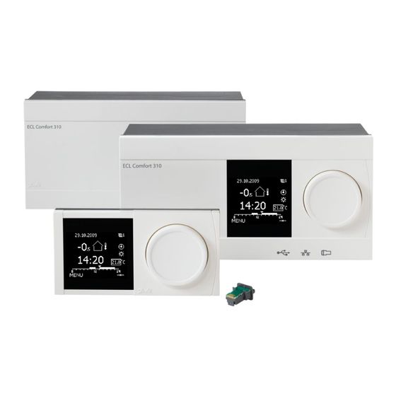
ECA 30 / 31 for ECL Comfort 210 / 210B / 310 / 310B
1.0 Table of Contents
1.0 Table of Contents ............................................. 1
2.0 User Guide....................................................... 2
2.1
Symbol overview . . . . . . . . . . . . . . . . . . . . . . . . . . . . . . . . . . . . . . . . . . . . . . . . . . 2
2.2
Introduction . . . . . . . . . . . . . . . . . . . . . . . . . . . . . . . . . . . . . . . . . . . . . . . . . . . . . . . . 3
2.3
Display information ECA 30 / 31. . . . . . . . . . . . . . . . . . . . . . . . . . . . . . . . . 4
2.4
Override functions ECA 30 / 31 . . . . . . . . . . . . . . . . . . . . . . . . . . . . . . . . . . 9
3.0 Installation ...................................................... 10
3.1
Important safety and product information. . . . . . . . . . . . . . . . . . . . 10
3.2
Mounting . . . . . . . . . . . . . . . . . . . . . . . . . . . . . . . . . . . . . . . . . . . . . . . . . . . . . . . . . . . 14
3.3
Placing the temperature sensors. . . . . . . . . . . . . . . . . . . . . . . . . . . . . . . . 15
3.4
Electrical connections. . . . . . . . . . . . . . . . . . . . . . . . . . . . . . . . . . . . . . . . . . . . . 16
3.5
ECA 30 / 31 setup procedures . . . . . . . . . . . . . . . . . . . . . . . . . . . . . . . . . . . 18
4.0 Settings........................................................... 26
4.1
Room temperature . . . . . . . . . . . . . . . . . . . . . . . . . . . . . . . . . . . . . . . . . . . . . . . . 26
4.2
Optimization. . . . . . . . . . . . . . . . . . . . . . . . . . . . . . . . . . . . . . . . . . . . . . . . . . . . . . . . 27
4.3
Holiday . . . . . . . . . . . . . . . . . . . . . . . . . . . . . . . . . . . . . . . . . . . . . . . . . . . . . . . . . . . . . . 28
Danfoss District Energy
VI.GU.V1.02
DEN-SMT/DK
1
Advertisement
Table of Contents


Need help?
Do you have a question about the ECA 30 and is the answer not in the manual?
Questions and answers