Worcester GB162-50 Installation And Servicing Instructions
Commercial
Hide thumbs
Also See for GB162-50:
- User instructions (12 pages) ,
- Installation instructions manual (12 pages) ,
- Operating instructions manual (12 pages)

Related Manuals for Worcester GB162-50


Summary of Contents for Worcester GB162-50
- Page 1 Installation and servicing instructions Wall hung gas fired condensing boiler Worcester Commercial Boiler Series GB162-50/65/80/100 For central heating systems and indirect fed domestic hot water UK/IE...
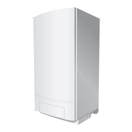
- Page 2 Product overview Product overview 6 720 648 726-001.1TD Fig. 1 GB162-50/65/80/100 with pump group 6720813171 (2015/04)
- Page 3 Product overview BC10 basic controller holder Installation option for room controller, e.g. RC35 BC10 basic controller, can be expanded e.g. by the RC35 room controller Connection box (low-voltage and 230V connections) Fan harness and mains lead of the pump Condensate drain outlet Condensate collector Boiler front door Automatic air vent...
-
Page 4: Table Of Contents
Combustion air flue gas connection ....9 8.5.5 230 V connections (only for GB162-50/65) ..29 Quality of the heating system water ....9 8.5.6 Installing function modules (accessories) . -
Page 5: Key To Symbols And Safety Instructions
APPLIANCE MODEL(S) STATED ON THE FRONT COVER OF THIS 15.2 Spare parts list GB162-50/65 ....66 MANUAL ONLY AND MUST NOT BE USED WITH ANY OTHER MAKE OR MODEL OF APPLIANCE. -
Page 6: Safety Instructions
Key to symbols and safety instructions The appliance contains no asbestos and no substances have been used Ø Diameter in the construction process that contravene the COSHH Regulations Automatic Bypass (Control of Substances Hazardous to Health Regulations 1988). Air Intake Connection COMBUSTION AND CORROSIVE MATERIALS Air Vent (automatic) Do not store or use any combustible materials (paper, thinners, paints... - Page 7 BS6880 Code of practice for low temperature hot water heating The design and construction of the Worcester Wall hung gas fired systems for output greater than 45 kW. condensing boiler conforms to the basic specifications listed in the...
-
Page 8: General
• 50, 65, 80 or 100: heating range in kW. country or region of final use. The GB162-50/65/80/100 is suitable for use as a single boiler or as part of a cascade system. CAUTION: Use this device for its intended purpose only. -
Page 9: Regulations And Directives
The pH of the heating system water must be between 7 and 8.5. If this is installation frame, horizontal headers, connection pipes for the boiler, not the case, please contact Worcester Customer Service before main gas pipe and vertical low loss header. -
Page 10: Safety
Safety Recycling Safety ▶ Dispose of the boiler's packaging material in an environmentally friendly manner. Please observe these instructions for your own safety. ▶ Dispose of those components of the heating installation (e. g. boiler Please observe these instructions or controller) which have to be replaced in an environmentally Observe the following instructions when installing and operating the friendly manner by handing them in at an authorised recycling facility. -
Page 11: Transporting The Boiler With A Trolley
Items supplied with boiler Items supplied with boiler The boiler is delivered factory-assembled. ▶ Check that the packaging is intact upon delivery. ▶ Check that all items have been supplied with the boiler. 6 720 648 726-003.1TD Fig. 3 Lift and carry the boiler correctly 6 720 648 726-005.1TD Fig. -
Page 12: Dimensions Of Boiler
CH (boiler) return; G1½" union nut with female thread [CS] Cap (DO NOT remove) [FGC/AIC] Flue gas/air intake connection: Ø 80/125 for GB162-50/65 and Ø 100/150 for GB162-80/100 [GAS] Gas connection to boiler; G1" female thread The servicing clearances required are: •... - Page 13 [CHR] CH (boiler) return; G1½" union nut with female thread [CS] Cap (DO NOT remove) [FGC/AIC] Flue gas/air intake connection: Ø 80/125 for GB162-50/65 and Ø 100/150 for GB162-80/100 [GAS B] Gas connection to boiler; G1" female thread [GAS P] Gas connection to pump group;...
-
Page 14: Installation
Installation ▶ Slide the boiler into place ( fig. 9). Installation This section explains how to install the boiler in a professional manner. Installing the boiler Observe the installation distances of the concentric flue gas system in the separate flue gas system manual. ▶... -
Page 15: General Connection Of Mains Water And Gas Components
Installation General connection of mains water and gas 8.2.3 Install the water and gas connections to the boiler without a pump group components ▶ Connect all pipes making sure that they are not bent or twisted to 8.2.1 General cause any stress. The water and gas connections to the boiler can be made in either of 2ways: CAUTION:... -
Page 16: Installing The Differential Pressure Controller
Installation ▶ Install the gas valve connector 1" [1] (accessory). ▶ Install the gas valve [2] onto the gas pipe. Use a gas valve with a minimum diameter of 1". G1” R1” 6 720 648 726-015.1TD Fig. 15 Connecting the boiler flow and return 6 720 648 726-014.1TD CH boiler flow CH boiler return... -
Page 17: Installing The Condensate Trap
Installation Select a pump with a residual head of at least 200 mbar at the minimum required volume flow ( table 4). GB162-50 GB162-65 GB162-80 GB162-100 2,200 3,000 3,600 4,300 Δ Table 3 Nominal required volume flow [l/h] at T = 20 K... - Page 18 Installation Material for condensate Ensure that the condensate trap is filled with water. The condensate drainage pipe should be run in a standard drain pipe material, e.g. PVC (polyvinyl chloride), PVC-U (unplasticized polyvinyl chloride), BS (acrylonitrile-butadienestyrene), PP (polypropylene polyprolene) or PVC-C (cross-linked polyvinyl chloride). Ø21.5 mm min.
-
Page 19: Connecting The Condensate Drain Pipe
Installation When discharging condensate to an outside drain caution must be taken to ensure blockage cannot occur during freezing conditions. If this is likely to occur, the use of a condensate trap is recommended. Ø21.5 mm min. 1000 mm min. 6 720 648 726-024.1TD Fig. -
Page 20: Flue Installation
Installation Flue Installation 8.3.1 Siting the flue terminal H, I 6 720 648 726-026.1TD Fig. 26 Balanced flue terminal position Terminal position Minimum spacing [mm]: Directly below, above or alongside an opening window, air vent or other ventilation opening Below guttering, drain pipes or soil pipes Below eaves Below balconies or a car port roof Not recommended! From vertical drain pipes or soil pipes... -
Page 21: Air Supply And Flue Gas Exhaust In A Room Sealed Installation
If this could occur the appliance must be turned off, and labelled as unsafe until corrective action can be taken. DANGER: ▶ Only use Worcester flue gas systems. As other flue 6 720 648 726-028.1TD gas systems are not tested with this appliance. -
Page 22: Maximum Flue Length (L)
Installation 8.3.3 Maximum Flue length (L) 8.3.4 Additional flue parts The maximum pipe length (L) of the air supply and flue gas exhaust pipes The additional flue parts listed can be ordered from your supplier. for the condensing gas system boilers is determined by the total Flue size 100/150 and 80/125 pressure loss of all components in the flue system. -
Page 23: Installation Of The Horizontal Flue
(contact Worcester Technical). The boiler is factory-fitted with a concentric connection. An air intake strainer basket can be used for operation dependent on room air. -
Page 24: Electrical Connections
▶ Secure the heating system so that it cannot be switched on again unexpectedly, pulling the mains plug from the wall socket. 90° bend Length=21m Pipe=2m The 230V converter can only be used for the GB162-50/65 appliance. 90° bend Maximum length Length=21m allowed after the boiler (GB162-80) 18 m 6 720 648 726-036.1TD... -
Page 25: Electrical Wiring Diagram
Installation 8.5.1 Electrical wiring diagram WARNING: ▶ Do not directly connect a 230 V thermostat to this boiler. Use the grey 230V connection box (supplied with GB162-50/65). Earth Ionisation Return sensor Safety-temperature sensor Flow sensor External connection for professional use... -
Page 26: Terminal Strip Connections
( section 7.5.4, page 36). 6 720 648 726-041.1TD Fig. 41 Routing the cable If uncertain how to connect controls to this appliance, first contact the Worcester technical helpline on 8.5.4 Description of the terminal strip connections 0330 123 3366 or your supplier. - Page 27 Connection for external three-way valve Fig. 44 Opening the control panel External heating pump 230 V (connection colour green) (for use with non Worcester pump group) ▶ Remove the cover [1]. DHW pump 230 V (connection colour grey) ▶ Install the RC35 in the slot [2].
- Page 28 The gas wall hung boiler condensing can be fitted with the following external controls: • a room-temperature control device at 230 V connected to the room control converter (only for GB162-50/65). For connection, see the electrical wiring diagram supplied with the 230 Volt converter), 6 720 648 726-048.1TD •...
-
Page 29: Connections (Only For Gb162-50/65)
( fig. 55). 6 720 648 726-052.1TD Fig. 52 Connection box - 230 Volt connection 8.5.5 230 V connections (only for GB162-50/65) NOTICE: 6 720 648 726-054.1TD The 230 V connections can only be used with a Fig. 54 230 VAC cable of the pump corresponding control unit. -
Page 30: Installing Function Modules (Accessories)
• Error reporting module EM10 Connecting to the mains • Switch module WM10 • Mixing module MM10 All Worcester boilers require a permanent live. • Solar module SM10. Function modules (accessories) can be installed in 2 ways: • in the boiler (max. 2) •... - Page 31 Installation ▶ Install the wall bracket (accessory with function module) in the ▶ Connect the free 230 VAC mains cable ( fig. 63) to the module relevant slots in the draw. [1]. If more modules are used, the 230 VAC supply for the second module can be taken from the first module using the cable enclosed with the module.
-
Page 32: Operation
3-core 0.75-mm² current cable with an fault, the fault can be remedied using the Service earthing wire. instructions. Contact Worcester if necessary. ▶ Connect the 230 VAC supply cable of the previous module to the See the back of this document for contact details. -
Page 33: Bc10 Control Operating Instructions
• Normal Operation menu • Flue Gas Test menu Service Tool connection • Service Mode menu This service connection is for Worcester service engineers only. • Manual Operation menu “Burner” (On/Off) LED • Settings menu. The “Burner” (On/Off) LED ( fig. 69, [6]) lights up when the burner of the boiler is active and it is extinguished when the burner is switched off. - Page 34 Operation Flue Gas Test menu [\/2/4| Step 1 Display value. Currently measured CH flow temperature in °C. Also see section 14.2, page 53. step 3 Step 2 Activate flue gas test? Yes: step 1 To activate the flue gas test: Press and hold the d button for more than 2 but not longer than 5 seconds Step 3 [\/2/4] Step 4...
- Page 35 Operation Service Mode menu [\/2/4| Step 14 Display value. Currently measured CH flow temperature in °C. Also see section 14.3, page 54. Press the e button. Step 15 [p/1.6| Step 16 Display value. Currently measured system pressure in bar. Also see section 14.3, page 54. Press the e button.
- Page 36 Operation Settings Menu [\/2/4| Step 1 Display value. Currently measured CH flow temperature in °C. Also see section 14.2, page 53. step 3 Step 2 Open the “Settings” menu? Yes: step 1 To open the “Settings” menu: Press and hold the d + e buttons for more than 2 seconds Step 3 [l/-/-] Display setting.
-
Page 37: Commissioning
If a fault occurs, then refer to the servicing manual or ▶ Turn the cap of the automatic air vent through one rotation to loosen contact Worcester. This section explains how to start up the boiler. ▶ Complete the commissioning record log book after carrying out the activities described below (... -
Page 38: Filling The Condensate Trap With Water
Commissioning ▶ Open the heating flow and return isolating valves on the pump group If the boiler has been in use for approximately one week and the pressure (open position: parallel to the pipe). reading on the display is less than 1.0 bar, the system has to be topped The pressure loss in a heating system is caused by air bubbles escaping via fittings and (automatic) air vent units. -
Page 39: Bleeding The Gas Flow Pipe
▶ Remove the hose and tighten the screw plug on the testing nipple again. NOTICE: ▶ Test the tightness of the measuring nipple(s) used. GB162-50/65 6 720 648 726-079.1TD Fig. 79 Open the gas valve ▶ Switch off the power supply to the heating system. -
Page 40: Checking The Flue Gas Connection
10.2.5 Checking the appliance configuration The burner must only be put into use with the right injectors ( table 14). Boiler Type of gas supply Gas injector diameter [mm] GB162-50 Natural gas H Venturi LPG 3P GB162-65 Natural gas H... -
Page 41: Checking And Adjusting The Gas/Air-Ratio
▶ Set the pressure gauge to “0”. pressure 20 mbar. • for LPG min. 30 mbar, max. 50 mbar, nominal supply pressure GB162-50/65 37 mbar. ▶ Press the “Service” button [4] repeatedly until the temperature reading is shown in the display. -
Page 42: Carrying Out A Leakage Test In Operating Conditions
Commissioning ▶ Set the capacity to minimum (part load) according to the “Service DANGER: Danger of fatal accident from explosive mode” menu ( table 11, page 34). fumes. ▶ After the “Burner” LED ( fig. 86, [6]) has lit up wait for one minute ▶... -
Page 43: Measuring The Flue Gases Co 2 Emissions
Commissioning 10.2.9 Measuring the flue gases CO emissions 10.2.11 Measuring the ionisation current ▶ Open at least 2 thermostatic radiator valves. Do not switch on the ▶ Push on the control panel to open it ( fig. 68, page 32). boiler. -
Page 44: Boiler Settings
Rated heating capacity at 40/30 °C [kW] Set the pump run-over time to 24 hours if the heating system is indication controlled depending on room temperature, and there is a risk of parts GB162-50 GB162-65 GB162-80 GB162-100 of the heating system not controlled by the room controller freezing (e.g. -
Page 45: Final Activities
Commissioning 10.4 Final activities ▶ Push on the control panel to close it. 10.4.1 Closing the boiler door and the control panel ▶ Close the boiler door and lock the fastener by turning the vent screw through ¼ rotation in a clockwise direction. 6 720 648 726-044.1TD Fig. -
Page 46: Shutting Down The Heating System
Shutting down the heating system ▶ Close the main gas supply or the gas valve ( fig. 81, page 39). Shutting down the heating system ▶ Drain the heating water at the lowest point of the heating system, using the drain cock or the radiator. The (automatic) air vent at the 11.1 Shutting down the heating system using the basic highest point of the heating system/radiator must be open. -
Page 47: Opening The Boiler Door
Inspection 12.4 Gas valve leakage test DANGER: Check the internal tightness of the gas fitting on the input side (with the Danger of fatal accident from explosive fumes. boiler switched off) at a test pressure of 20 mbar for natural gas. ▶... -
Page 48: Inspection Log Book
Maintenance 12.12 Inspection log book ▶ Enter your signature and the date after completing the inspection activities. Inspection activities Date: ________ Date: ________ Date: ________ Checking the general condition of the heating system. Carrying out a visual inspection and function test of the heating system. -
Page 49: Cleaning The Heat Exchanger, Burner And Condensate Trap
The boiler has a self-cleaning coating. the connector lock to loosen it. WARNING: Damage to the installation due to short circuits. GB162-50/65 ▶ Do not spray the detergent onto the burner, the glow ignitor, the ionisation electrode or other electrical components. -
Page 50: Removing The Burner And The Burner Seal
Maintenance ▶ Carefully open the 4 snap closures on the burner cover. The snap 13.2.4 Checking ignition unit closures may be under tension. CAUTION: Damage to the glow ignitor. ▶ Remove the snap closures. ▶ The glow ignitor is fragile. Handle with care. NOTICE: If the seat of the cover plate leaks, the seal can burn away. -
Page 51: Disconnecting The Condensate Trap
Maintenance 13.2.5 Disconnecting the condensate trap 13.2.6 Removing the condensate collector ▶ Disconnect the condensate trap hose [3] and the rubber sleeve [2] ▶ Disconnect the flexible condensate drain hose and bend it from the condensate trap [1]. backwards. ▶ Turn the trap clockwise a quarter turn. 6 720 648 726-115.1TD 6 720 648 726-113.1TD Fig. -
Page 52: Cleaning The Heat Exchanger
Maintenance 13.2.7 Cleaning the heat exchanger ▶ Refit the condensate collector. ▶ Connect the flexible condensate drain hose to the condensate CAUTION: Damage to the installation. collector. ▶ Do not use metal brushes or similar hard cleaning ▶ Re-install the condensate trap. tools. -
Page 53: Display Information
BC10 basic controller and what they mean. For exact troubleshooting instructions please refer to the boiler service instructions. You may also contact Worcester technical support (0330 123 3366) 14.1 Removing the control panel from the boiler To make it easier to use the buttons on the control panel when the boiler... -
Page 54: Bc10 Display Settings
Display information 14.3 BC10 Display settings Display settings Factory Display adjusted setting Meaning of display setting Unit Range setting [l/9/9| [l/3/0| – [l/9/9| / [l/-/-| 100 % [l/-/-| Configured target load (50 kW). [l/9/9| [l/2/0| – [l/9/9| / [l/-/-| 100 % [l/-/-| Configured target load (65 kW). - Page 55 Display information Display codes Display code Main Reset display display requi- LED on code code Key to display code red? UBA 3 Other effects [0/c/\| [2/8/3| Pre-operative phase: The boiler prepares for a burner start-up whenever a heat demand or a DHW request arises. [0/e/\| [2/6/5| Readiness for operation:...
- Page 56 Display information Display codes Display code Main Reset display display requi- LED on code code Key to display code red? UBA 3 Other effects [2/y/\| [2/8/2| Fault: No feedback from the pump. [3/a/\| [2/6/4| Fault: 4) 5) The tacho signal from the fan has failed during the operating phase.
- Page 57 Display information Display codes Display code Main Reset display display requi- LED on code code Key to display code red? UBA 3 Other effects [6/a/\| [2/2/7| Fault: flashing No heating operation and no 1 Hz DHW. 5) 6) 7) The system has detected an insufficient ionisation current after four start-up attempts.
- Page 58 Display information Display codes Display code Main Reset display display requi- LED on code code Key to display code red? UBA 3 Other effects [9/u/\| [2/3/3| Fault: flashing No heating operation and no 1 Hz DHW. 5) 6) 7) The UBA 3 or the KIM is defective. [a/0/1| [8/0/0| Fault:...
- Page 59 Display information Display codes Display code Main Reset display display requi- LED on code code Key to display code red? UBA 3 Other effects [a/1/1| [8/2/3| Fault: Since there is no actual room temperature information, RC35-HK1 remote control. No remote control assigned, room influence and although frost protection type “FROST”...
-
Page 60: Re-Fit The Control Panel In The Boiler
Display information Display codes Display code Main Reset display display requi- LED on code code Key to display code red? UBA 3 Other effects [a/3/2| [8/0/7| Fault: Heating circuit pump 2 is activated depending on the The contacts to the heating circuit flow sensor have preset value. -
Page 61: Technical Specifications
Technical specifications Technical specifications The technical specifications serve to provide information about the boiler performance profile. Unit GB162-50 GB162-65 GB162-80 GB162-100 Rated thermal load for G20 14.6 - 47.5 14.6 - 62.0 19.3 - 82.0 19.3 - 96.5 Rated heating capacity, heating curve 80/60 °C 14.2 - 46.6... - Page 62 Technical specifications Pump group Pump group Unit GB162-50/65/80/100 General Pump group components Casing, gas isolating valve, pressure relief valve, stop valves, check valves, drain cock, pressure gauge, pump. Pump type UPER 25-80 pump group UPER 25-80 UPS 25-80 pump group...
-
Page 63: Spare Parts List Gb162-80/100
Technical specifications 15.1 Spare parts list GB162-80/100 Description Product No. The following are parts commonly required due to damage or O-ring (10 pc) 7101488 replacements. Their failure will affect safety or performance of this Ignitor housing (incl. glow ignitor and 8718600172 appliance. - Page 64 Technical specifications Exploded view GB162-80/100 44 45 6 720 648 726-124.1TD 6720813171 (2015/04)
- Page 65 Technical specifications Exploded view pump group GB162-80/100 6 720 648 726-125.1TD 6720813171 (2015/04)
-
Page 66: Spare Parts List Gb162-50/65
Technical specifications 15.2 Spare parts list GB162-50/65 Description Product No. For a pictorial representation of the part see the respective position Ignitor housing (incl. glow ignitor and 8718600172 number on the exploded view pictures on page 68 and 69. ionisation electrode) - Page 67 Technical specifications Description Product No. 126 Body three way valve 20374 127 Motor three way valve 20375 128 Three way valve complete 20373 129 Check valve 7746900606 130 Repair set three way valve 1”+ 5/4” 75400 131 Valve housing supply (single) 74547 Valve housing supply (combi) 74548...
- Page 68 Technical specifications Exploded view GB162-50/65 44 45 6 720 648 726-126.1TD 6720813171 (2015/04)
- Page 69 Technical specifications Exploded view pump group with DHW GB162-50/65 6 720 648 726-127.1TD 6720813171 (2015/04)
- Page 70 Notes 6720813171 (2015/04)
- Page 71 Notes 6720813171 (2015/04)
- Page 72 0330 123 9779 LITERATURE: 0330 123 9119 TRAINING: 0330 123 0166 SALES: 0330 123 9669 Worcester, Bosch Group Cotswold Way, Warndon, Worcester WR4 9SW. Tel. 0330 123 9559 Worcester, Bosch Group is a brand name of Bosch Thermotechnology Ltd. worcester-bosch.co.uk 6720813171...
Need help?
Do you have a question about the GB162-50 and is the answer not in the manual?
Questions and answers