Worcester Greenstar Ri User Manual
Wall hung rsf gas fired condensing boiler
Hide thumbs
Also See for Greenstar Ri:
- Installation and servicing instructions (68 pages) ,
- User instructions & customer care manual (16 pages)
Table of Contents
Advertisement
THE APPLIANCE IS FOR USE WITH
NATURAL GAS OR L.P.G. (Cat II 2H3P TYPE C13 & C33)
NATURAL GAS: 24Ri GC NUMBER 41-311-65
LIQUID PETROLEUM GAS: 24Ri GC NUMBER 41-311-66
GB/IE
CHECKLIST & service
interval record is printed at the rear of
this manual
18Ri GC NUMBER 41-311-77
15Ri GC NUMBER 41-311-75
12Ri GC NUMBER 41-311-63
18Ri GC NUMBER 41-311-78
15Ri GC NUMBER 41-311-76
12Ri GC NUMBER 41-311-64
Advertisement
Table of Contents

Related Manuals for Worcester Greenstar Ri


Summary of Contents for Worcester Greenstar Ri
- Page 1 THE APPLIANCE IS FOR USE WITH NATURAL GAS OR L.P.G. (Cat II 2H3P TYPE C13 & C33) NATURAL GAS: 24Ri GC NUMBER 41-311-65 18Ri GC NUMBER 41-311-77 15Ri GC NUMBER 41-311-75 12Ri GC NUMBER 41-311-63 LIQUID PETROLEUM GAS: 24Ri GC NUMBER 41-311-66 18Ri GC NUMBER 41-311-78 15Ri GC NUMBER 41-311-76 12Ri GC NUMBER 41-311-64...
- Page 2 THIS APPLIANCE MUST BE INSTALLED BY A COMPETENT PERSON. FAILURE TO INSTALL CORRECTLY COULD LEAD TO PROSECUTION. IF YOU ARE IN ANY DOUBT CONTACT THE WORCESTER BOSCH TECHNICAL HELPLINE. WATER TREATMENT: DISTANCE LEARNING AND TRAINING COURSES ARE AVAILABLE FROM WORCESTER...
-
Page 3: Table Of Contents
GAS. CONVERSION FAULT FINDING & DIAGNOSIS ELECTRICAL WIRING DIAGRAM FAULT FINDING MAIN FUNCTION BENCHMARK CHECKLIST & SERVICE RECORD SHEET PRINTED AT THE REAR OF THE MANUAL INSTALLATION & SERVICING INSTRUCTIONS FOR WORCESTER BOSCH GREENSTAR Ri CONTENTS 8 716 109 699a (05/05) -
Page 4: Safety Precautions & Symbols
IMPORTANT - The service engineer must complete the Service Record on the Benchmark Checklist after each service. INSTALLATION & SERVICING INSTRUCTIONS FOR WORCESTER BOSCH GREENSTAR Ri SAFETY PRECAUTIONS 8 716 109 699a (05/05) -
Page 5: General Information
Modulating automatic gas valve Combustion air fan with speed regulator CH temperature sensor & control External pump anti-seizure protection Flue gas temperature limiter Condensate trap & syphon INSTALLATION & SERVICING INSTRUCTIONS FOR WORCESTER BOSCH GREENSTAR Ri GENERAL INFORMATION 8 716 109 699a (05/05) -
Page 6: Technical Data
27.4 27.4 27.4 27.4 27.4 Lift weight 22.6 22.6 22.6 22.6 22.6 22.6 22.6 22.6 SEDBUK 90.1 90.1 90.1 90.2 91.4 91.4 91.4 92.0 INSTALLATION & SERVICING INSTRUCTIONS FOR WORCESTER BOSCH GREENSTAR Ri TECHNICAL DATA 8 716 109 699a (05/05) -
Page 7: Layout & Components
28 RETURN CONNECTION 22mm COMPRESSION 29 HEAT EXCHANGER 30 GAS COCK (ACCESS POINT) 31 SILICONE TUBE (USE TO VENT AIR FROM HEAT EXCHANGER) INSTALLATION & SERVICING INSTRUCTIONS FOR WORCESTER BOSCH GREENSTAR Ri LAYOUT & COMPONENTS 8 716 109 699a (05/05) -
Page 8: Cleaning Primary Systems
5 Drain and thoroughly flush the system to remove the flushing agent and debris. Valve Flushing Agent INSTALLATION & SERVICING INSTRUCTIONS FOR WORCESTER BOSCH GREENSTAR Ri CLEANING PRIMARY SYSTEMS 8 716 109 699a (05/05) -
Page 9: Mains Supply
This does not include the pipework from the meter to the boiler. INSTALLATION & SERVICING INSTRUCTIONS FOR WORCESTER BOSCH GREENSTAR Ri MAINS SUPPLY 8 716 109 699a (05/05) -
Page 10: Water Systems & Pipework
• NB A drain cock should be fitted at the lowest point of the heating circuit and beneath the appliance. INSTALLATION & SERVICING INSTRUCTIONS FOR WORCESTER BOSCH GREENSTAR Ri WATER SYSTEMS & PIPEWORK 8 716 109 699a (05/05) -
Page 11: Condensate Pipework
H - Ground level J - Drainage holes 50mm from base of tube (12mmØ at 25mm centres) facing away from building K - Limestone chippings INSTALLATION & SERVICING INSTRUCTIONS FOR WORCESTER BOSCH GREENSTAR Ri CONDENSATE PIPEWORK 8 716 109 699a (05/05) -
Page 12: Boiler Location & Clearances
INSTALLATION & SERVICING INSTRUCTIONS FOR WORCESTER BOSCH GREENSTAR Ri BOILER LOCATION & CLEARANCES 8 716 109 699a (05/05) - Page 13 Electrical switches, fused spur and socket out let s must not be sit uat ed in t he bathroom. INSTALLATION & SERVICING INSTRUCTIONS FOR WORCESTER BOSCH GREENSTAR Ri BOILER LOCATION & CLEARANCES 8 716 109 699a (05/05)
-
Page 14: Plumbing Manifold
• If the flow and return pipes are to be run behind the appliance it maybe an advantage to connect the pipes before hanging on the wall especially if space is limited. Return Flow INSTALLATION & SERVICING INSTRUCTIONS FOR WORCESTER BOSCH GREENSTAR Ri PLUMBING MANIFOLD 8 716 109 699a (05/05) -
Page 15: Flue Terminal Positions
See instructions supplied with vertical flue kits. Care should be taken to ensure terminal siting does not cause a nuisance to adjacent properties. INSTALLATION & SERVICING INSTRUCTIONS FOR WORCESTER BOSCH GREENSTAR Ri FLUE TERMINAL POSITIONS 8 716 109 699a (05/05) -
Page 16: Flue Options
B x 4 + C x 2 + E x 1 Vertical 80/125mm: 1365mm to top of terminal Ø125 - 11000mm (including terminal) B x 13 + C x 2 + E x 1 INSTALLATION & SERVICING INSTRUCTIONS FOR WORCESTER BOSCH GREENSTAR Ri FLUE OPTIONS 8 716 109 699a (05/05) -
Page 17: Installation
Before installing appliance ensure system has been cleaned as explained on page 8. NOTE: Carefully cut along perferated line to release wall template. INSTALLATION & SERVICING INSTRUCTIONS FOR WORCESTER BOSCH GREENSTAR Ri UNPACKING THE BOILER 8 716 109 699a (05/05) -
Page 18: Wall Mounting Plate Flue Opening
Allow for a rise of 52mm per metre length of flue, to give a 3° angle. Clear any debris from the site. INSTALLATION & SERVICING INSTRUCTIONS FOR WORCESTER BOSCH GREENSTAR Ri WALL MOUNTING PLATE FLUE OPENING 8 716 109 699a (05/05) -
Page 19: Outer Case Removal
3. Pull case upwards. 4. Remove cardboard packing piece from appliance. With the outer case removed the appliance is suitable for a 1 man lift (<25kg). INSTALLATION & SERVICING INSTRUCTIONS FOR WORCESTER BOSCH GREENSTAR Ri OUTER CASE REMOVAL 8 716 109 699a (05/05) -
Page 20: Boiler Connections (Gas/Water)
22mm compression fitting (pipe not supplied). 22mm Ø 22mm Ø (Not supplied) 22mm Ø Pipes in alternative position Condensate outlet 112mm A, B and C 18mm INSTALLATION & SERVICING INSTRUCTIONS FOR WORCESTER BOSCH GREENSTAR Ri BOILER CONNECTIONS 8 716 109 699a (05/05) -
Page 21: Flue Installation
250mm. After cutting the end must be square and free from burrs to prevent damage to the flue seals. (250mm min) Turret Clamp Flue INSTALLATION & SERVICING INSTRUCTIONS FOR WORCESTER BOSCH GREENSTAR Ri FLUE INSTALLATION 8 716 109 699a (05/05) - Page 22 98mm per bend must be allowed from the centre line of the bend. In the example shown using a flue extension with 2 bends will achieve a total length of 1148mm. INSTALLATION & SERVICING INSTRUCTIONS FOR WORCESTER BOSCH GREENSTAR Ri FLUE INSTALLATION 8 716 109 699a (05/05)
-
Page 23: Flue Installation
• The flue is set at an angle 3° or 52mm per 1m length. Flat at back This screw should be fitted last for easier installation INSTALLATION & SERVICING INSTRUCTIONS FOR WORCESTER BOSCH GREENSTAR Ri FLUE INSTALLATION 8 716 109 699a (05/05) -
Page 24: Condensate Connections
50mm per metre towards the outlet. • An adapter in 22mm pipe is contained in the fitting pack (A) along with sealing washer (B). INSTALLATION & SERVICING INSTRUCTIONS FOR WORCESTER BOSCH GREENSTAR Ri CONDENSATE, GAS & WATER 8 716 109 699a (05/05) -
Page 25: Electrics
Refit electric control panel covers: Refit panel (B) and secure with screws. Locate lugs at top edge of panel (A) and clip in at base. INSTALLATION & SERVICING INSTRUCTIONS FOR WORCESTER BOSCH GREENSTAR Ri ELECTRICS 8 716 109 699a (05/05) -
Page 26: Position Of Wired Components
POSITION OF WIRED COMPONENTS INSTALLATION & SERVICING INSTRUCTIONS FOR WORCESTER BOSCH GREENSTAR Ri POSITION OF WIRED COMPONENTS 8 716 109 699a (05/05) -
Page 27: Pre-Commissioning Checks
INSTALLATION & SERVICING INSTRUCTIONS FOR WORCESTER BOSCH GREENSTAR Ri PRE-COMMISSIONING CHECKS 8 716 109 699a (05/05) -
Page 28: Filling The System
Test for gas supply for soundness as described in BS 6891. INSTALLATION & SERVICING INSTRUCTIONS FOR WORCESTER BOSCH GREENSTAR Ri FILLING THE SYSTEM 8 716 109 699a (05/05) -
Page 29: Starting The Appliance
2 seconds then turn to maximum. The boiler will be reset. CAUTION: DO NOT PRESS POWER INDICATOR (B) TO RESET BOILER. RESET INSTALLATION & SERVICING INSTRUCTIONS FOR WORCESTER BOSCH GREENSTAR Ri STARTING THE APPLIANCE 8 716 109 699a (05/05) -
Page 30: Water Treatment
Inhibitor * compatible with aluminium. The pH value of the system water must be less than 8 or the appliance guarantee will be invalidated. WATER TREATMENT INSTALLATION & SERVICING INSTRUCTIONS FOR WORCESTER BOSCH GREENSTAR Ri 8 716 109 699a (05/05) -
Page 31: Commissioning
Re-seal the screw in the gas inlet pressure test point. Inlet Test Nipple Replace controls cover. Note: This boiler is designed with differential of 20°C across the heating system. INSTALLATION & SERVICING INSTRUCTIONS FOR WORCESTER BOSCH GREENSTAR Ri COMMISSIONING 8 716 109 699a (05/05) -
Page 32: Finishing Commissioning
User Guide. If the appliance is unused and exposed to freezing conditions; shut off all the mains supplies and drain the system and boiler. INSTALLATION & SERVICING INSTRUCTIONS FOR WORCESTER BOSCH GREENSTAR Ri FINISHING COMMISSIONING 8 716 109 699a (05/05) -
Page 33: Inspection And Service
Refill and re-pressurise if applicable as described in Commissioning. Operate the appliance and take note of any irregularities. Refer to Fault Finding for rectification procedures. INSTALLATION & SERVICING INSTRUCTIONS FOR WORCESTER BOSCH GREENSTAR Ri INSPECTION AND SERVICE 8 716 109 699a (05/05) - Page 34 2. Adjusting boiler control to service position 2.1 Remove two screws (D) securing control. 2.2 Hang control on two lugs (E) on boiler framework. INSTALLATION & SERVICING INSTRUCTIONS FOR WORCESTER BOSCH GREENSTAR Ri INSPECTION AND SERVICE 8 716 109 699a (05/05)
- Page 35 24kW - 3. 1 mbar - 4. 1 mbar After measurement replace test point cover and return mode switch to normal. Replace controls cover. INSTALLATION & SERVICING INSTRUCTIONS FOR WORCESTER BOSCH GREENSTAR Ri INSPECTION AND SERVICE 8 716 109 699a (05/05)
- Page 36 3.3 Remove syphon Syphon The syphon body is transparent so contents can be examined for any blockage. If necessary flush with clean water. INSTALLATION & SERVICING INSTRUCTIONS FOR WORCESTER BOSCH GREENSTAR Ri INSPECTION AND SERVICE 8 716 109 699a (05/05)
- Page 37 Disconnect spark electrode and flame sensor connections (J). Remove clamping plate (K). Remove spark/flame electrode assembly from boiler. Remove seal from the top of the heat exchanger INSTALLATION & SERVICING INSTRUCTIONS FOR WORCESTER BOSCH GREENSTAR Ri INSPECTION AND SERVICE 8 716 109 699a (05/05)
-
Page 38: Inspection And Service
BETWEEN THE AIR/GAS MANIFOLD AN D TH E H EAT E XCHANG E R I S DISTURBED THE SEALING GASKET MUST BE REPLACED. INSTALLATION & SERVICING INSTRUCTIONS FOR WORCESTER BOSCH GREENSTAR Ri INSPECTION AND SERVICE 8 716 109 699a (05/05) -
Page 39: Setting The Gas / Air Ratio
The power indicator will flash and the boiler will stay in this mode for 15 minutes if no further change is made to the switch. NORM INSTALLATION & SERVICING INSTRUCTIONS FOR WORCESTER BOSCH GREENSTAR Ri SETTING THE GAS / AIR RATIO 8 716 109 699a (05/05) - Page 40 – Please note: The flue gas test point can be accessed on the appliance flue elbow by removing cap C INSTALLATION & SERVICING INSTRUCTIONS FOR WORCESTER BOSCH GREENSTAR Ri SETTING THE GAS / AIR RATIO 8 716 109 699a (05/05)
-
Page 41: Replacement Of Parts
Note: It is essential that the mating surface of the thermostat is coated with heat conductive paste. 4. Flue limit thermostat Remove electrical connections. Unscrew thermostat from flue. INSTALLATION & SERVICING INSTRUCTIONS FOR WORCESTER BOSCH GREENSTAR Ri REPLACEMENT OF PARTS 8 716 109 699a (05/05) - Page 42 Drop condensate tube away from syphon. 8.2 Remove two screws (F) retaining the bracket. 8.3 Rotate syphon 90° to the left and remove. INSTALLATION & SERVICING INSTRUCTIONS FOR WORCESTER BOSCH GREENSTAR Ri REPLACEMENT OF PARTS 8 716 109 699a (05/05)
- Page 43 IMPORTANT: ENSURE CODE PLUG IS RE-FITTED TO THE NEW CONTROL. IF THIS IS NOT DONE THE BOILER WLL INDICATE ERROR AND WILL NOT FUNCTION. INSTALLATION & SERVICING INSTRUCTIONS FOR WORCESTER BOSCH GREENSTAR Ri REPLACEMENT OF PARTS 8 716 109 699a (05/05)
- Page 44 Refit new pressure switch to bracket. I M PORTANT: E N S U R E TU B E I S REFITTED TO PRESSURE SWITCH 13.4 13.1 13.2 13.3 INSTALLATION & SERVICING INSTRUCTIONS FOR WORCESTER BOSCH GREENSTAR Ri REPLACEMENT OF PARTS 8 716 109 699a (05/05)
-
Page 45: Replacement Of Parts
17.4 Undo flue connection from sump. Pull heat exchanger assembly up to clear. Reassemble and check combustion as stated in the gas converstion section. 17.4 17.2 17.3 17.1 INSTALLATION & SERVICING INSTRUCTIONS FOR WORCESTER BOSCH GREENSTAR Ri REPLACEMENT OF PARTS 8 716 109 699a (05/05) -
Page 46: Short Parts List
WHS Part No. 8 716 106 506 0 GC No. H26-545 12 Seal - door WHS Part No. 8 716 106 635 0 H26-546 GC No. INSTALLATION & SERVICING INSTRUCTIONS FOR WORCESTER BOSCH GREENSTAR Ri SHORT PARTS LIST 8 716 109 699a (05/05) -
Page 47: Conversion Kits
Reassemble control box and replace outer case. Code plugs 12kW NG 12kW LPG 15kW NG 15kW LPG 18kW NG 18kW LPG 24kW NG 24kW LPG INSTALLATION & SERVICING INSTRUCTIONS FOR WORCESTER BOSCH GREENSTAR Ri GAS CONVERSION 8 716 109 699a (05/05) -
Page 48: Electrical Wiring Diagram
12. S2, Service mode selector switch 13. ST8, No connection. 14. Temperature control and lockout reset. 15. ST9 connector 16. Flame sense electrode, Pin 1 = green. INSTALLATION & SERVICING INSTRUCTIONS FOR WORCESTER BOSCH GREENSTAR Ri ELECTRICAL WIRING DIAGRAM 8 716 109 699a (05/05) -
Page 49: Fault Finding
FAULT FINDING NOTE : This fault finding information is for guidance only. Worcester, Bosch cannot be held responsible for costs incurred by persons not deemed to be competent. The electronic control system for this boiler incorporates a blue central indicator. This normally confirms the permanent mains supply but, by flashing at different rates during a fault, provides a guide to the cause as listed. -
Page 50: Main Function
MAIN FUNCTION INSTALLATION & SERVICING INSTRUCTIONS FOR WORCESTER BOSCH GREENSTAR Ri MAIN FUNCTION 8 716 109 699a (05/05) - Page 51 BENCHMARK No. GAS BOILER COMMISSIONING CHECKLIST C O L L E C T I V E M A R K BOILER SERIAL No. NOTIFICATION No. CONTROLS To comply with the Building Regulations, each section must have a tick in one or other of the boxes TIME &...
-
Page 52: Service Interval Record
SERVICE INTERVAL RECORD It is recommended that your heating system is serviced regularly and that you complete the appropriate Service Interval Record Below. Service Provider. Before completing the appropriate Service Interval Record below, please ensure you have carried out the service as described in the boiler manufacturer’s instructions. - Page 53 INSTALLATION, COMMISSIONING & SERVICING EXCELLENCE COMES AS STANDARD Worcester, Bosch Group Cotswold Way, Warndon, Worcester WR4 9SW. Tel. 01905 754624 Fax. 01905 754619 Worcester, Bosch Group is a trading name of BBT Thermotechnology UK Ltd. www.worcester-bosch.co.uk 8 716 109 699a (05/05)
Need help?
Do you have a question about the Greenstar Ri and is the answer not in the manual?
Questions and answers
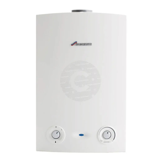
How do I start my boiler
To start the Worcester Greenstar Ri boiler, follow these steps:
1. Turn on the mains power supply – The power indicator (2) will illuminate BLUE.
2. Turn on any external controls such as the room thermostat and programmer.
3. Set the thermostatic radiator controls to maximum temperature.
4. Set the clock/programmer to continuously ON and the room thermostat to maximum temperature.
5. Turn the Power ON/OFF knob (1) from 0 (OFF position) to I (ON position). After 2 seconds, the Power ON indicator (2) will illuminate.
If the boiler fails to light and goes into flame lock-out, reset it by turning the boiler thermostat control to the minimum position, then past minimum until it clicks at the reset position. Wait 5 seconds, then turn it to maximum to reset the boiler.
This answer is automatically generated