Table of Contents
Advertisement
Quick Links
Advertisement
Table of Contents

Related Manuals for Black Horce Model SUKHOI 31 BH11


Summary of Contents for Black Horce Model SUKHOI 31 BH11
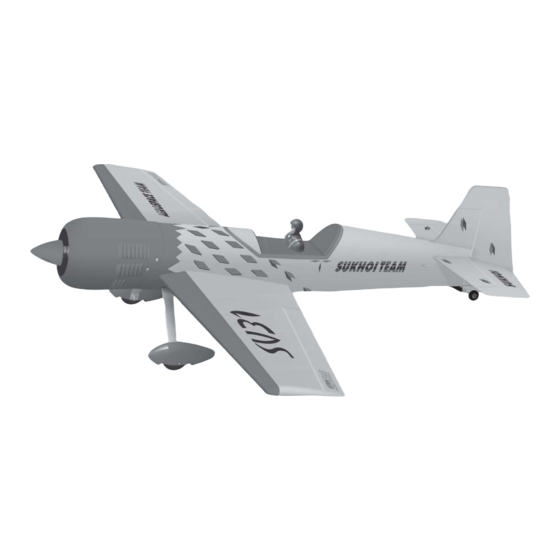
- Page 1 Instruction Manual book ITEM CODE: BH11. SPECIFICATION Wingspan : 1,400 mm 55 in. Length 1,250 mm 49 in. Weight 2.6 kg 5.72 Lbs. Radio 04 channels.
-
Page 2: Instruction Manual
SUKHOI 31. Instruction Manual This instruction manual is designed to help you build a great flying aeroplane. Please read this manual thoroughly before starting assembly of your SUKHOI SU31. Use the parts listing below to identify all parts. WARNING. Please be aware that this aeroplane is not a toy and if assembled or used incorrectly it is capable of causing injury to people or property. -
Page 3: Safety Precaution
SUKHOI 31. INSTRUCTION MANUAL SAFETY PRECAUTION. + This is not a toy + Be sure that no other flyers are using your Cut the covering radio frequency. away from the slot. + Do not smoke near fuel + Store fuel in a cool, dry place, away from children and pets. - Page 4 SUKHOI 31. Instruction Manual 5. Instal servo tray with aileron servo into the wing as same as picture below. Wing. Servo tray. 3. Drill 1,5mm pilot holes through the block of wood for each of the four mounting screws provided with the servo.
- Page 5 SUKHOI 31. INSTRUCTION MANUAL 2. Locate nylon control horn, nylon con- trol horn backplates . 3. Drill through 6mm (diameter) the aileron using the control horn as a guide and screw the control horn in place. Aileron Control horn 6mm (diameter) ...
-
Page 6: Installing The Aileron Linkages
SUKHOI 31. Instruction Manual C/A glue. 4. Locate one nylon servo arm, and using wire cutters,remove all but one of the arms. Using a 2mm drill bit, enlarge the third hole out from the center of the arm to accommo- date the aileron pushrod wire. -
Page 7: Installing The Engine Mount
SUKHOI 31. INSTRUCTION MANUAL Remove covering. Masking tape. Apply masking tape. 3. Test fit the dihedral brace into each wing half. The brace should slide in easily. Masking tape. INSTALLING THE ENGINE MOUNT. See pictures below: Epoxy glue. Aluminium brace. - Page 8 SUKHOI 31. Instruction Manual INSTALLING THE ENGINE MOUNT. 3x20mm. cut. 4x25mm. FUEL TANK. INSTALLING THE STOPPER ASSEMBLY...
- Page 9 SUKHOI 31. INSTRUCTION MANUAL 1. The stopper has been pre-assembled at the factory. 2. Using a modeling knife, cut one length of silicon fuel line (the length of silicon fuel line is calculated by how the weighted clunk should rest about 8mm away from the rear of the tank and move freely inside the tank).
-
Page 10: Installing The Engine
SUKHOI 31. Instruction Manual Do not secure the tank into place perma- nently until after balancing the airplane. You may need to remove the tank to mount the battery in the fuel tank compartment. INSTALLING THE ENGINE. Locate the long piece of wire used for the throttle pushrod. - Page 11 SUKHOI 31. INSTRUCTION MANUAL COWLING. 1. Slide the fiberglass cowl over the en- gine and line up the back edge of the cowl with the marks you made on the fuselage. Secure. Trim and cut. Pushrod wire.
-
Page 12: Installing The Spinner
SUKHOI 31. Instruction Manual INSTALLING THE SPINNER. Install the spinner backplate, propeller and 2. While keeping the back edge of the spinner cone. The spinner cone is held in cowl flush with the marks, align the front of place using two 3mm x 15mm wood screws. the cowl with the crankshaft of the engine. -
Page 13: Elevator Installation
SUKHOI 31. INSTRUCTION MANUAL 2. Draw a center line onto the horizontal stabilizer. Then slide the horizontal into the fuselage. Bottom side. ELEVATOR INSTALLATION. 1. Install the rubber grommets and brass collets into the elevator servo. Test fit the servo Cut the covering into the servo tray. - Page 14 SUKHOI 31. Instruction Manual 5. When you are sure that everything is aligned correctly, mix up a generous amount of 30 minute epoxy. Apply a thin layer to the top and bottom of the stabilizer mounting area and to the stabilizer mounting platform sides in the fuselage.
-
Page 15: Elevator Control Horn Installa- Tion
SUKHOI 31. INSTRUCTION MANUAL Drill 1 hole with 6 mm diameter. ELEVATOR CONTROL HORN INSTALLA- TION. Elevator control horn install as same as the way of aileron control horn. Please see pic- tures below. Nilon M3 lock nut control clasp. 3mm x 40mm. -
Page 16: Elevator Pushrod Installation
SUKHOI 31. Instruction Manual C/A glue. Elevator control horn. ELEVATOR PUSHROD INSTALLATION. Elevator pushrod install as same as the way of aileron pushrod. Elevator C/A glue. pushrod. C/A glue. Top side. Bottom side. -
Page 17: Vertical Installation
SUKHOI 31. INSTRUCTION MANUAL C/A glue. Snap keeper. Cut. Bend. VERTICAL INSTALLATION. Rudder servo. Bend and cut after. Elevator servo. - Page 18 SUKHOI 31. Instruction Manual Control clasp. Control clasp. Hinge. Hinge. 1) Using a modeling knife, remove the covering from the top of the fuselage and the covering from over the precut hinge slot cut into the lower rear portion of the fuselage This slot accepts the lower vertical.
- Page 19 SUKHOI 31. INSTRUCTION MANUAL Epoxy glue. Pen. 4. Now, remove the rudder and using a modeling knife, carefully cut just inside the marked lines and remove the film of the rud- der. Just as you did with the horizontal stabi- lizer, make sure you only press hard enough to cut the film, not the balsa rudder.
-
Page 20: Rudder Control Horn Installa- Tion
SUKHOI 31. Instruction Manual RUDDER CONTROL HORN INSTALLA- TION. Rudder control horn install as same as the way of aileron control horn. Please see pic- tures below. C/A glue. Pen. Mark a hole. Nilon M3 lock nut control clasp. 3mm x 40mm. Control horn of Rudder. -
Page 21: Installing The Switch
SUKHOI 31. INSTRUCTION MANUAL INSTALLING THE THROTTLE PUSHROD. 1. Install one adjustable metal connector through the third hole out from the center of one servo arm, enlarge the hole in the servo arm using a 2mm drill bit to accommodate the servo connector. - Page 22 SUKHOI 31. Instruction Manual INSTALLING THE RECEIVER AND BATTERY. 1. Plug the servo leads and the switch lead into the receiver. You may want to plug an aileron extension into the receiver to make plugging in the aileron servo lead easier when you are installing the wing .
- Page 23 SUKHOI 31. INSTRUCTION MANUAL Secure. Drill a hole. 3) Using the hardware provided, mount the main landing gear to the fuselage. Trim. 2) A drop of C/A glue on the wheel collar screws will help keep them from coming lose during operation.
-
Page 24: Mounting The Tail Wheel Bracket
SUKHOI 31. Instruction Manual MOUNTING THE TAIL WHEEL BRACKET. 1. Set the tail wheel assembly in place on the plywood plate. The pivot point of the tail wheel wire should be even with the rud- der hinge line and the tail wheel bracket should be centered on the plywood plate. - Page 25 SUKHOI 31. INSTRUCTION MANUAL Remove covering. Insert. BALANCING. 1) It is critical that your airplane be bal- anced correctly. Improper balance will cause your plane to lose control and crash. THE CENTER OF GRAVITY IS LOCATED 100-115mm BACK FROM THE LEADING EDGE OF THE WING.
-
Page 26: Pre-Flight Check
SUKHOI 31. Instruction Manual Accurately mark the balance point on the top Ailerons : 10mm up 10mm down of the wing on both sides of the fuselage. The Elevator : 15mm up 15mm down balance point is located 100-115mm back from Rudder : 30mm right 30mm left the leading edge. - Page 27 SUKHOI 31. INSTRUCTION MANUAL...
Need help?
Do you have a question about the SUKHOI 31 BH11 and is the answer not in the manual?
Questions and answers