Advertisement
INSTALLATION INSTRUCTIONS FOR PART 95-5820
95-5820
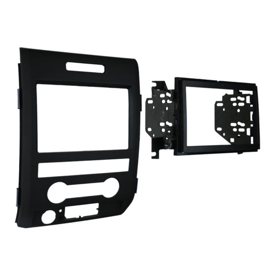
KIT FEATURES
• Double DIN Radio Provision
• Stacked ISO Mount Units Provision
KIT COMPONENTS
• A) Double DIN Radio Housing • B) Double DIN Radio Housing Brackets
• C) Radio Housing Trim Panel • D) (6) U Style Panel Clips
A
B
• Cutting Tool • Phillips Screwdriver • Socket Wrench • Torx Driver
1-800-221-0932
© COPYRIGHT 2009 METRA ELECTRONICS CORPORATION
APPLICATIONS
FORD
F-150 2009
D
WIRING AND ANTENNA CONNECTIONS
(Sold Separately)
Harness:
• Please see www.metraonline.com for
specific interface harness
Antenna Adapter:
C
• 40-CR10 - Chrysler antenna adapter 02-up
TOOLS REQUIRED:
• Panel Removal Tool
www.metraonline.com
Advertisement
Table of Contents

Summary of Contents for Metra Electronics 95-5820
- Page 1 INSTALLATION INSTRUCTIONS FOR PART 95-5820 F-150 2009 95-5820 KIT FEATURES • Double DIN Radio Provision • Stacked ISO Mount Units Provision KIT COMPONENTS • A) Double DIN Radio Housing • B) Double DIN Radio Housing Brackets • C) Radio Housing Trim Panel • D) (6) U Style Panel Clips •...
-
Page 2: Kit Preparation
Final Assembly ......... . .5 *Note: Refer also to the instructions included with the aftermarket radio. 95-5820 NOWLEDGE IS Enhance your installation and fabrication skills by enrolling in the most recognized and respected mobile electronics school in our industry. - Page 3 Note: It is not nec- essary to remove the panels com- pletely. (Figure C) Unclip and remove the radio trim panel. (Figure D) Continued on page 2. 95-5820 DASH DISASSEMBL Y FORD F-150 2009...
- Page 4 Remove (4) Torx screws securing the factory climate control to the radio trim panel. (Figure G) Remove (4) 9/32” screws to remove the factory radio. Continue to final preparation. 95-5820 DASH DISASSEMBL Y FORD F-150 2009 FACTORY RADIO TRIM PANEL-REAR VIEW...
- Page 5 Attach the (6) U style panel clips to the radio housing in the same location as the factory radio trim panel. (Figure D) Continue to kit assembly. KIT REPLACEMENT RADIO TRIM PANEL-REAR VIEW 95-5820 KIT PREPARATION FORD F-150 2009 KIT REPLACEMENT RADIO TRIM PANEL-REAR VIEW...
- Page 6 ISO mount units. (Figure B) Cut and remove half of the top (2) mounting legs with the brackets attached. (Figure C) Continue to final assembly. CUT HERE - 95-5820 KIT ASSEMBL Y TOP LEG ONLY CUT HERE TOP LEG ONLY...
- Page 7 Re-connect the negative battery terminal and test the unit for proper operation. Reassemble radio and dash assemblies in reverse order of disassembly using the 95-5820 radio housing in place of the factory radio trim panel. FINAL WIRING CONNECTIONS Make wiring connections using the EIA color code chart shown below and the instructions included with the head unit.
- Page 8 95-5820 INSTRUCTIONS www.metraonline.com 1-800-221-0932 REV. 05/07/09 © COPYRIGHT 2009 METRA ELECTRONICS CORPORATION INST95-5820...


Need help?
Do you have a question about the 95-5820 and is the answer not in the manual?
Questions and answers