Table of Contents
Advertisement
Quick Links
Advertisement
Table of Contents

Related Manuals for V-tech IP-MR18S


Summary of Contents for V-tech IP-MR18S
-
Page 1: Door Station
IP-MR18S Door Station User Manual RF CARD Please read this manual carefully before using the product you purchase, and keep it well for future use. We reserve the right to modify the specification in this manual at any time without notice. -
Page 2: Table Of Contents
Contents 1. Parts and Functions ........1 2. Terminal Descriptions .......1 3. Door Station Mounting ......2 4. Basic System Connection ......3 5. Door Lock Connections ......4 6. Door Station Configurations ......5 7. Software,UI And Voice Data Updating ..9 8. How to use code unlock function ....10 9. -
Page 3: Parts And Functions
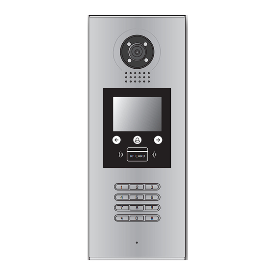
1. Parts and Functions Camera Lens Night View LED Adjustable Camera Speaker LCD Screen Touch Key Connectiong Port ID Card Window RF CARD Digital Keypad Microphone 128 mm With rainy cover 2. Terminal Descriptions SD Card Slot RS-485 CN-LK T/R - T/R+ JWB(OUT) J/KMB... -
Page 4: Door Station Mounting
3. Door Station Mounting Camera angle Drill a hole and attach the The view for rainy Adjust the camera angle and attach the rainy cover to it cover after mounted metal to the panel and wire correctly. Attach screws to fix the Attach the unit to the rainy Attach the baffle to protect metal box... -
Page 5: Basic System Connection
4. Basic System Connection The basic system consists of: Door station, Distributor, Monitor, Power supply and lock. Connect to next C5-F4 C5-F4 C5-F4 CN-LK RS-485 RF CARD RF CARD T/R - T/R+ JWB(OUT) JP-LK 12 V DC lock J/KMB 85~260AC... -
Page 6: Door Lock Connections
5. Door Lock Connections 1. Internal Power Supply Mode Note that the door station can only output 12Vdc power, Any high-power lock should use ex- ternal power connection ,or it might cause damage to the door station. • The rated power of the lock must be less than 12Vdc 300mA when using internal power supply mode; • The GND must connect to the negative of the lock, and the COM connect to the positive; • It's recommended that the jumper set to 2-3 position for Power-on-to-Unlock safety type(Normally open mode); • If different unlocking time is needed to be configured, change the Unlock Timing on door station. Connection for Power-on-to-Unlock type: set to Normally open on the +12V Unlock Relay mode... -
Page 7: Door Station Configurations
6. Door Station Configurations About Debug State: The Debug State is your starting point for using all the applications. To open the debug state,please refer to the following steps: RF CARD [ 9 0 0 8 ] When Door Station is in Input '9008', then input the Debug State menu is launched standby, press '#' key Admin Code.(66666666 by default) Press "2#" key to exit out the debug state. About Debug Tools: During working at Debug State,press "1#" to enter tools page,Debug Tools overview is shown as below:... - Page 8 Table 1:Menu overview Item Submenu 1. ID Code [0-11] 2. Unlock Timing [01] 3. Unlock Output [0] 4. Monitor Timing [030] 5. Doorplate Mode [0] 1. Installer Setup 6. Waiting Timing [030] 7. Talking Timing [090] 8. Installer Code ... 9. Default ... 1. Language [0] 2. Tone Select [01] 3. Tone Volume [3] 4. Unlock Code [1111] 5. Card Memory [0] 2. Setup 6. Clock ... 7. Setup Code 8. About 9. Default ... 1. Add Card ... 2. Delete By Card 3. Delete By M.code 3. Card Manage 4. Cards Information 5. Format To search the online monitors,input the monitor code 4. Online Monitors number to search To search the online door stations.Max.4 door station 5.
- Page 9 Basic Tools Detail: Table 2(Installer Setup): Factory Item Description 1. When there is only one door station and no C5-IPC, set to 0. And set the type of distributor used with it. When C5-IPC is connected, must not be set to 0. 1. ID Code Single 2. When C5-MDS is connected, be set to from 1~8 according to which port it is connected on the C5-MDS 3. When used as common door station, set to 9 To set the time that how long the door keeps open [01] 2. Unlock Timing when door is released. Range from 01 to 99 seconds. 1 seconds To set the unlock mode to match the corresponding lock.Range from 0 to 1. 3. Unlock Output 0:Power-on-to-Unlock Mode(Normally Open Mode) 1:Power-off-to-Unlock Mode(Normally Closed Mode) 4. Monitor Timing To show the monitor time,Range from 6s to 600s 600s To set the calling mode.If set to 0,it's the auto mode,that means the calling will be activated directly 5. Doorplate Mode after inputting 4 digits code.If set to 1,it's the manual Auto mode mode,that means you should press "#" button to acti- vate the calling after inputting the code. 6. Waiting Timing To show the calling wait time,Range from 6s to 600s To show the limitation time of talking,Range from 6s to 7. Talking Timing 600s 8. Installer Code ...
- Page 10 Table 3(Setup): Factory Item Description 1. Language reserved. 2. Tone Select Select the chime of Door Station in calling wait state. Adjust the tone volume for door station in calling.Range 3. Tone Volume from 01~15 To change unlock code in Common Code Unlock mode, 4. Unlock Code 1111 in 4-digits format. 1111 is the default unlock code. To choose to use the memory of door station or that of C5-IPC when access cards are in use 5. Card Memory 0-Use memory of DS for access 1-Use C5-IPC for access To set date and time. Date format:if set to 0,date format is DD/MM/YY,if set to 6. Clock ... 1,date format is MM/DD/YY. Time format: if set to 0,time format is 24 hour standard.If set to 1,time format is12 hour standard.
-
Page 11: Software,Ui And Voice Data Updating
Table 4(Card Manage): Factory Item Description 1. Add Card ... To add the user card 2. Delete By Card To delete card by user card 3.Delete By M.code To delete card by room code 4. Cards Information To show the informations about cards 5. Format To format informations about cards * Note that you can use another way(#+8007+66666666) to enter the Card Manage mode. 7. Software,UI And Voice Data Updating It's convenient for user to change the software, UI, Namelist data, or voice data. Just put the config files to the SD card and insert the SD card into door station and by means of the digital keypad ,only 30 seconds is needed to update. Insert SD card RS-485 CN-LK T/R - T/R+ JWB(OUT) J/KMB JP-LK... -
Page 12: How To Use Code Unlock Function
1 Firmware update 2 Voice update 3 UI update RF CARD RF CARD 4 Namelist update [ 8014 ] [ 66666666 ] Select (1~4) to update When the Door Station is in Input " 66666666 " The update item menu standby, Press " #+8014 8. How to use code unlock function: Please refer to the following operations: RF CARD RF CARD... -
Page 13: Change Unlcok Code
9. Change Unlcok Code: If door station runs as Debug State, you can press “1#” to activate Tools Menu, then select “2” to enter setup page,then select 4 item.If it runs as Normal State, follow these steps: 4 . U n l o c k C o d e [ 1 1 1 1 ] [ - - - - ] RF CARD [ 8002 ] ( * * * * ) Press “#”,Input “8002”, Press “4” to enter unlock On this page, [1111] is the... -
Page 14: User Card Management
10. User Card Management: This section explains how to configure the key fob function on IP-MR18S, The key fob is used to open the lock. Total 320 key fobs can be registered with one door station. When swiping the fob to the door station, the distance must be less than 3 centimeter. Key Fobs must be registered on the Door station that can be used to open the door. Register the Key Fobs: All the registered key fobs are called User Cards/User Key Fobs. New fobs/cards need to be registered one by one to the Door station to become a valid User Card/User Key Fob; and every User Card/User Key Fob is related to a certain Monitor Address (Flat code). When the Doors tation is standby, press [#] --> [9008] -->Password([66666666 by default]) to get into the Debug Mode Menu, then Press [1 #] --> [3] Card Manage -->[1] Add Card to get into the Add Card page. Please see the followings. 1 . A d d C a r d . . . 1 . A d d C a r d . . . -
Page 15: Specification
Delete By Card: In Debug State , Press [1 #] --> [3] Card 2 . D e l e t e B y C a r d 2 . D e l e t e B y C a r d Manage -->[2] Delete By Card to enter Delete by Card page.as shown on the right, then show the cards you want to S h o w T h e C a r d C a r d N u m b s : 0 0 0 1 2 5 7 8 9... - Page 16 C5-ENG-IP-MR18S-V1 2015S1126...
Need help?
Do you have a question about the IP-MR18S and is the answer not in the manual?
Questions and answers