
Related Manuals for V-tech DT601/FP


Summary of Contents for V-tech DT601/FP
- Page 1 English 2-Wire Video Outdoor Station User Manual DT601/FP DT601F/FP DT-ENG-601(F)FP-V1 141023...
-
Page 2: Parts And Functions
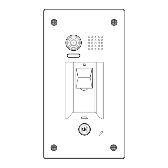
Night Light LED 1 Fingerprint window 30 mm KEY 1 KEY 2 LED 2 Call Button Microphone Rainy Cover 93 mm DT601/FP Camera Lens Speaker Night Light LED 1 Fingerprint window KEY 1 KEY 2 LED 2 Call Button Microphone... -
Page 3: Door Station Mounting
S- will not be connected). 3.Door Station Mounting 3.1 DT601/FP Mounting Drill holes in the wall to match the size of Connect the cable correctly screws and attach the rainy cover to the wall. -
Page 4: System Wiring And Electric Lock Connection
3.2 DT601F/FP Mounting Drill a hole in the wall to match the size of the Connect the cable correctly mounting box and attach to the wall. Attach the panel to the mounting box and use screws supplied to fix the panel 4. -
Page 5: Electric Lock Connection
4.2 Electric Lock Connection 4.2.1 Door Lock Controlled with Internal Power Note: 1. Electronic lock of Power-on-to-unlock 1 2 3 type should be used. Jumper position in 2-3 2. The door lock is limited to 12V, and holding current must be less than 250mA. -
Page 6: Unlock Parameter Setting(Set On Monitor)
4.3 Unlock parameter setting(set on monitor) INSTALLER SETUP About Local Address 00.00 Video Standard AUTO System Verson 00.01.00 Display Driver Front 1.Touch icon on 2.Touch UNLOCK 3.A digital keypad will main menu page. button and hold for 2s. be shown. Note: 1.must connect DT601(F)/FP correctly before setting. -
Page 7: Multi Monitors Connection
4.5 Multi Monitors Connection 4.5.1 Basic IN-OUT Wiring Mode Code=15 Code=14 Code=0 100~240VAC BUS(IM) BUS(DS) (Device Address:0) NOTE:Here we take DT47M(the monitor) for example. - Page 8 4.5.2 With DBC4A Wiring Mode Impedance Code=15 Code=14 OFF ON switch Code=13 Code=12 Code=3 Code=2 Impedance OFF ON switch Code=1 Code=0 100~240VAC BUS(IM) BUS(DS) (Device Address:0) NOTE:Here we take DT47M(the monitor) for example.
- Page 9 5. Setup 5.1 ID of Doorstation Settings The ID of doorstation can be set to ID0/ID1/ID2/ID3.The default is ID0. 1)Power-on within 10 seconds; Press and hold "KEY1" and 2)Press and hold "KEY2" button "KEY2" button for 3 seconds at for 3 seconds, it will enter the the same time, it will enter the setting state of prepare.
-
Page 10: Unlock Time Settings
5.2 Unlock Time Settings The unlock time can be set to 1~30 seconds. The default is 1s. 1)Power-on within 10 seconds; Press and hold "KEY1" button for 2)Press and hold "KEY2" button 3 seconds, it will enter the state for 3 seconds, it will enter the of unlock time setting. - Page 11 5.3 Ringtone Mode Settings The system supports three ringtone modes: [A]one ringtone, [B] continuous ringtone, [C]forbid ringtone. The default is one ringtone. 1)Power-on within 10 seconds; Press and hold "KEY2" button for 2)Press and hold "KEY2" button 3 seconds, it will enter the state for 3 seconds, it will enter the of ringtone mode setting.
- Page 12 6. Register [Management Fingerprint] [Management Fingerprint] will serve as a registered or delete credential of user fingerprint. The system can only store a management fingerprint. 6.1 Register [Management Fingerprint] When the system has never been registered [Management Fingerprint], you can according to the following operation to register [Management Fingerprint].
- Page 13 6.2 Update [Management fingerprint] When the system has been registered [Management Fingerprint], you can according to the following operation to register new [Management Fingerprint]. 1)Power-on within 10 seconds; Touch original [Management 2)Press and hold "KEY1" button for Fingerprint], make [Management 3 seconds;...
- Page 14 7. Register User Fingerprints User fingerprints will serve as a unlock credential for user. The system can store 200 user fingerprints. 7.1 Add User Fingerprints Press "KEY1" button, It will enter Tonch the [Management Fingerprint] In the standby mode; the state of add user fingerprints It will enter the state of user setting fingerprints setting...
- Page 15 7.2 Delete Specified User Fingerprint Press "KEY2" button, It will enter Tonch the [Management Fingerprint] In the standby mode; the state of delete specified user It will enter the state of user fingerprints setting fingerprints setting LED 1 LED 2 Buzzer LED 1 LED 2...
- Page 16 7.3 Delete All User Fingerprints Press and hold "KEY1" and Tonch the [Management Fingerprint] In the standby mode; "KEY2" button at the same time, It will enter the state of user It will enter the state of delete all fingerprints setting user fingerprints setting LED 1 LED 2...
-
Page 17: Specifications
• Power Consumption: Standby 34mA; Working status 158mA; • Camera: Color ARS; 500 TV Lines; • Lock Power supply: 12Vdc, 280mA(Internal Power); • Mounting: Surface mounting(DT601/FP) Flush mounting (DT601F/FP) • Working temperature: -15ºC ~ +55ºC • Wiring: 2 wires,non-polarity • Dimension: 182(H)×93(W)×44(D)mm(DT601/FP) -
Page 18: Cables Requirements
10. Cables Requirements The maximum distance of the wiring is limited in the DT system. Using different cables may also affect the maximum distance which the system can reach. The farest monitor monitor with two or four monitors monitor monitor DBC4A 100~240VAC When Monitor quantity <... - Page 19 -18-...
- Page 20 The design and specifications can be modified without notice to the user. Right to interpret and copyright of this manual are reserved. DT-ENG-601(F)FP-V1 141023...
Need help?
Do you have a question about the DT601/FP and is the answer not in the manual?
Questions and answers