
Related Manuals for Polaroid Joshua Vision


Summary of Contents for Polaroid Joshua Vision
- Page 1 Repair Manual Joshua (Vision/JoyCam/Captiva) April 1993 Americas Business Center Technical Services 201 Burlington Road Bedford MA 01730 TEL: 1.781.386.5309 FAX: 1.781.386.5988...
-
Page 2: Table Of Contents
Polaroid Joshua Camera Service Manual Table of Contents Description ....................... 1-1 Introduction ....................... 1-3 Unique Joshua Differences ..................1-2 In-Camera Picture Storage .................. 1-4 Compact Camera Size ..................1-5 Unique Microprocessor Controlled Exposure System .......... 1-7 Key Joshua Features ....................1-8 Using the Camera ...................... - Page 3 Exposing the Picture .................... 2-12 Blocking the Viewfinder ..................2-13 Releasing the Taking Mirror ................2-14 Processing the Exposed Frame ................2-16 Reseating the Taking Mirror and Opening the Viewfinder Blind ......2-19 Special Cases ......................2-23 Darkslide when Film Door is Opened and Closed ..........2-23 Folding the Camera during a Processing Cycle ............
- Page 4 Front Panel ........................ 4-8 Removal ......................4-8 Reassembly ......................4-8 Left Hand Grip and Bottom Chute Cover ..............4-9 Removal ......................4-9 Reassembly ......................4-9 Bottom Chute Cover ....................4-10 Disassembly ......................4-10 Reassembly ......................4-10 Right Hand Grip ......................4-11 Disassembly ......................
- Page 5 Main Frame (Gear Side - Outer) ................4-33 Disassembly ......................4-33 Reassembly ......................4-34 Main Frame (Gear Side - Inner) ................4-35 Disassembly ......................4-35 Reassembly ......................4-35 Troubleshooting ..................... 5-3 Introduction ......................5-3 Functional Test of a Joshua Camera ................5-5 Tools and Parts Needed for Troubleshooting ............
- Page 6 [This page intentionally blank]...
-
Page 7: Description
1. Description 1 - 1... - Page 8 1. Description Table of Contents Introduction ........................... 1-3 Unique Joshua Differences ....................1-4 In- Camera Picture Storage ....................1-4 Compact Camera Size ..................... 1-5 Unique Microprocessor Controlled Exposure System ............1-7 Key Joshua Features ......................1-8 Using the Camera ........................1-10 Loading Film ........................
-
Page 9: Introduction
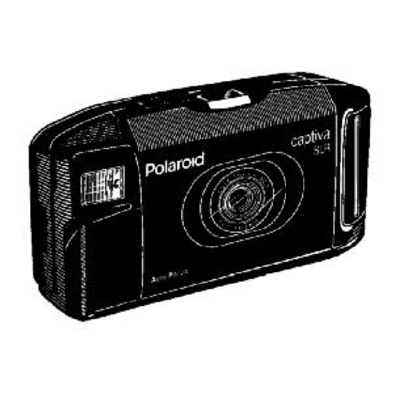
Description Introduction The Polaroid Joshua is a compact, folding, single-lens reflex camera which stores its own finished pictures and the darkslide. Camera operation is fully automatic and produces 10 full-color, instant Polaroid pictures from one Joshua film pack. Picture format can be either vertical or horizontal. -
Page 10: Unique Joshua Differences
Unique Joshua Differences Three major, unique design goals have been successfully achieved in the Joshua Camera: • Storage of finished pictures within the Camera • Compact size with extremely rugged construction • Improved exposure control and picture sharpness under virtually all lighting conditions Each of these Joshua differences will now be briefly described. -
Page 11: Compact Camera Size
Compact Camera Size When folded, the Joshua Camera measures about 57 x 96 x 180 mm (2.25 x 3.79 x 7.1") and weighs 760 gm (27 oz) with a full film pack. The Camera is erected by holding the camera as shown and depressing the Release Button Latch on the Strobe Tower with your right thumb (Figure 1-3). - Page 12 Film Loading and Picture Removal Doors provide access to the film pack compartment and the picture chamber, respectively (Figure 1-4). Loading a film pack into the Camera and closing the Film Door brings the pack to the image plane and automatically transports the darkslide into the storage chamber, unless this chamber is full.
-
Page 13: Unique Microprocessor Controlled Exposure System
Unique Microprocessor-Controlled Exposure System (Figure 1-5) Significant improvement in exposure accuracy and picture sharpness, under virtually every conceivable picture-taking condition, has been achieved in the Joshua. The Camera uses entirely new methods of measuring and controlling the ambient and strobe contributions to exposure, and optimizing the shutter aperture at which the exposure is made. - Page 14 Key Joshua System Features (Figure 1-6) • Automatic focus, automatic exposure, automatic flash with rapid recharge (less than 5.3 seconds between shots), automatic film advance. • High-quality multi-element optics: Three-element, 107mm lens (front element is coated glass). Aperture range f/12 to f/72. Use of accessory close-up lens adds another lens element. •...
- Page 15 Figure 1-6. Joshua System Features 1 - 9...
-
Page 16: Using The Camera
Note: See the Operator’s Instruction booklet for more information. Loading Film Use only Polaroid Joshua instant film. Film may be loaded (Figure 1-7) with Camera erected or collapsed: Camera is easier to handle when collapsed. Open film door by sliding the door latch; lift the door up and slide film pack in. -
Page 17: Taking Picture
Taking Picture Hold Camera horizontally or vertically (keep flash on top), frame your picture and press shutter button (Figure 1-9). (If Viewfinder is black, Camera is not fully erected — push flash tower forward until it clicks.) If green LED is not lighted, touch shutter button lightly to charge flash. The picture advances automatically into the storage compartment, over the previous pictures. -
Page 18: Brightness Adjustment And Self-Timer
Brightness Adjustment and Self-Timer To reshoot a picture that is too dark, move the Brightness Override Switch toward the white-dot arrow (Figure 1-11). To take a darker picture, move the Switch to the left, toward the black-dot arrow. (Camera must be erected; Switch will reset to normal when Camera is collapsed.) To operate Self-Timer, set Camera on tripod, frame picture and slide switch toward clock symbol (it will spring back). -
Page 19: Major Functional Sub-Systems Of The Joshuacamera
Major Functional Subsystems of the Joshua Camera Note: The following descriptions and illustrations are intended to familiarize you with what the Camera subsystems are. How these subsystems work is covered in the Theory of Operation section. Erecting, Viewfinder and Camera Optical System Figure 1-12 shows in simplified form the linkage which erects the Camera and accurately positions the optical elements for viewing the scene and exposing the picture. - Page 20 The image path through the single-lens reflex viewfinder, from the scene to the camera user’s eye, is shown in Figure 1-13. From the taking lens, the image is directed onto a fixed viewing mirror at 45 degrees . . . then to a textured fresnel focusing screen .
- Page 21 As shown in Figure 1-14, a second mirror — the taking mirror — is mounted on the underside of the fresnel screen. When the shutter button is fully depressed, the pivoted fresnel screen/taking mirror assembly is unlatched and driven upward into the optical path to the 45-degree angle position shown. A fraction of a second earlier, a blind was moved into place within the viewfinder window to prevent stray light from reaching the film.
-
Page 22: Drive And Switching System
Drive and Switching Systems You will note similarities between some of the components of the Joshua drive system shown in Figures 1- 15 and 1-16, and comparable parts of Spectra/Image, 640, Impulse and SX-70 drives — for example, motor-driven reduction gear train, single-revolution timing gear with cammed surfaces, counter wheel, pick assembly and wireform switches. - Page 23 Figure 1-16. Principal Parts of the Joshua Drive System 1 - 17...
-
Page 24: Shutter System
Shutter System (Figures 1-17, 1-18 and 1-19) Key components of the Joshua shutter system, shown in Figure 1-17, include the Front Lens, Far Focus Lens and its Solenoid 2, Walking Beam, Inertia System, the two Blades and their Solenoid 1 and Ambient/ IR Lens. - Page 25 Figure 1-18. Joshua Blade Position Encoder System Ambient Visible and IR levels are measured by a dual- photocell Photometer on the PC board, through green and black lenses on the lens mounting plate and corresponding apertures in the shutter blades. Each of these exposure components —...
- Page 26 The microprocessor determines which zone to use, based on IR reflectance data resulting from the strobe wink. (Although the electronics uses the wink mode to determine whether the subject is near or far from the camera, the primary purpose of the wink mode is to predict the strobe fire aperture.) When the Far Focus Lens is needed, it is pivoted into the optical path by Solenoid 2 and latched by the Lens Latch and Latch Actuator (Figure 1-19).
-
Page 27: Film Frame Transport And Spreading
At the same time the frame enters the Feed Rolls, a mechanical Film Shade (similar in function to the frog’s tongue in other Polaroid cameras) is automatically positioned over the first 1.9 cm (.75") of the picture Viewing Window. The Film Shade prevents light-piping fogging of undeveloped film through its transparent mylar coating. - Page 28 Figure 1-20. Film Frame Transport, Spreading and Storage Figure 1-21. Features for Even Reagent Distribution in Pod 1 - 22...
-
Page 29: Specification Summary
Camera Type Folding, single-lens reflex with integral strobe and picture storage/viewing in camera. Film Type Polaroid Joshua instant color print film; 10 exposures per pack with integral mercury-free battery. Frame Size 11.1 x 6.4 cm (4-3/8" x 2-1/2"). Image Size 7.3 x 5.5 cm (2-7/8"... - Page 30 Components, Covers and Panels Figure 1-22 on the following foldout page is an exploded view showing principally the removable parts, panels and covers of the Joshua Camera. Please note that this illustration is for general information only and NOT intended as a disassembly guide or representation of major sub-assemblies of the camera.
- Page 31 Figure 1-22. Joshua Components, Covers,and Panels 1 - 25...
- Page 32 [This page intentionally blank]...
-
Page 33: Theory Of Operation
2. Theory of Operation 2 - 1... - Page 34 2. Theory of Operation Table of Contents Sequence of Operation ......................2-3 Stages of Operation ....................... 2-3 Loading Filmpack into Erected or Folded Camera ............2-3 Powering Folded Camera for Dark-Slide when Filmpack is Inserted ....... 2-6 Powering Camera when Film Door is Closed, Latched and then Erected ......2-8 Maintaining Power for Processing after Camera is Folded ..........
-
Page 35: Sequence Of Operation
Theory of Operation Sequence of Operation Figure 2-1 shows an overall, pictorial summary of the entire sequence of operations from power up through processing, followed by detailed descriptions of what happens during each of the major stages. Note: A Circuit Diagram of the Joshua Camera is included at the end of this section. - Page 36 Figure 2-1. Pictorial Chart Showing Joshua Camera Sequence of Operation...
- Page 37 The film pack frame and platen assembly mounted on the film loading door permit easy insertion and removal of a film pack. As shown in Figure 2-2, these parts accurately position the topmost frame in the correct optical plane for exposure, when the door is closed. Figure 2-2.
- Page 38 As you would expect, this switch powers the camera circuits after the VER to Gnd contact is opened and the VER to B+ contact is closed. The VER and B+ wires are variously actuated by the door latch, lower erect link or the film shade lug, depending on whether the camera is folded or erected. For clarity, therefore, only the parts which are operative in a given situation will be shown in each of the following explanations.
- Page 39 As the door is latched, the Door Latch cam rotates the Door Latch Sensor CCW, allowing the B+ wire to drop and contact VER (Figure 2-6). Power is now made and darkslide occurs. The Film Shade moves to the left into its blocking position, then returns. Figure 2-6.
-
Page 40: Powering Camera When Film Door Is Closed, Latched And Then Erected
Powering Camera when Film Door is Closed, latched and then Erected As shown in Figure 2-8, a cam surface on the Door Latch engages the end of the Door Latch Sensor. Closing and latching the Door pivots the Sensor CCW, allowing the B+ wire to drop, but not far enough to contact VER when the camera is in the folded position. -
Page 41: Maintaining Power For Processing After Camera Is Folded
If the camera is now folded, the reverse happens: VER opens from B+ and is then shorted to GND. This discharges a capacitor in the Power Supply, so that when the Camera is later erected, the microprocessor knows the strobe should be topped off. As mentioned above, it is the Door Latch, not the Door, that affects the B+ wire of the Power Switch. - Page 42 But, as shown in Figure 2-11, the Film Shade has moved to the left, into its blocking position. A lug on one edge of the Film Shade has slid under the finger on the Power Actuator, pivoting the Actuator upward. The molded tab or shoulder on the Actuator is now snug up against VER, in contact with B+.
-
Page 43: Darkslide Transport And Counter Wheel Indexing
Darkslide Transport and Counter Wheel Indexing The third and fourth results of loading a film pack into the camera are the darkslide cycle and picture counter decrementing (counting down) or indexing. When power is made as VER closes to B+, the microprocessor checks the status of the Full Chamber, EOP (End of Pack) and DKEC (Dark Slide End Of Cycle) Switches. -
Page 44: Exposing The Picture
During the forward stroke of the Pick Carrier, the Counter Wheel (Figure 2-14) is indexed by a spring arm on the Pick Carrier. The Counter detent acts as a ratchet. After one full revolution, the Timing Gear cam allows the Outer Door Stop Link to rotate CCW, opening the DKEC switch which signals the microprocessor to shut off the motor. -
Page 45: Blocking The Viewfinder
Blocking the Viewfinder The motor is momentarily run in reverse, rotating the Recock Latch a short distance counterclockwise (Figure 2-15). (The Latch, on the same shaft as the Clutch Gear, is turned by the leg of a one-way-slip wrap spring on the hub of the Clutch Gear. When the motor reverses the Clutch Gear, the spring tightens on its hub and turns with it, also turning the Recock Latch. -
Page 46: Releasing The Taking Mirror
Figure 2-16. Recock Latch Pivots Viewfinder Blind Upward Through Viewfinder Blind Link and Blind Overtravel Spring Releasing the Taking Mirror As previously described, the brief motor reversal rotated the Recock Latch a few degrees counterclockwise. This action frees the Recock Link to pivot upward from the force of the stretched Recock Link Spring (see Figure 2-17). - Page 47 Figure 2-18. Recock Link Drives Taking Mirror Carrier into Position for Exposure As described in the Exposure section of the Sequence of Operations, ambient and wink measurements are now made, strobe fire aperture selected from the lookup table, Solenoid 1 released, blade position carefully monitored and the strobe is fired —...
-
Page 48: Processing The Exposed Frame
Processing the Exposed Frame The motor now runs forward, rotating the Timing Gear which cams the Outer Door Stop Link to close DKEC (Figure 2-19). Another cam, on the underside of the Timing Gear, drives the Pick Carrier forward (to the left) to its full stroke and holds it there (Figure 2-20). - Page 49 Figure 2-21. Spring Arm on Pick Carrier Indexes Counter Wheel The Pick Carrier also drives the Override Slider in the Door. The Slider actuates the Film Shade through a reversing linkage, moving the Film Shade into position to cover approximately the first 1.9 cm (.75") of unexposed film (Figure 2-22).
- Page 50 The exposed frame is now pulled into the Feed Rolls by the notched Pick Strap — a pivoted, spring-loaded arm attached to the end of the Pick Carrier (see Figure 2-23). The Feed Rolls drive the frame around the chute. Figure 2-23.
-
Page 51: Reseating The Taking Mirror And Opening The Viewfinder Blind
Reseating the Taking Mirror and Opening the Viewfinder Blind To return the Taking Mirror to its down position, the Recock Link is pivoted downward by yet another cam on the underside of the Timing Gear (Figure 2-24). Figure 2-24. Taking Mirror Carrier Driven Down by Recock Link As the Recock Link swings down, it pulls the Taking Mirror Carrier down, through the Midlink and Mirror Hold-Down Spring. - Page 52 The Latch is rotated by a combination of the Recock Latch Spring and the drag of the spring clutch in the overrunning direction. As the Recock Latch rotates clockwise, it pulls the Blind down through the Viewfinder Blind Link, uncovering the Viewfinder Window. The Timing Gear has now rotated to a position where its DKEC cam releases the Outer Door Stop Link, opening the DKEC switch.
- Page 53 The final stages of processing involve the frame being fed into the Spread Rolls and spread, and the Timing Gear rotating to a position where the Pick Carrier Advance/Hold Forward cam on its underside allows the Pick Carrier to retract under its own spring tension. The Override Slider (part of the Storage Chamber Pick Assembly), under its own spring load, follows the Pick Carrier.
- Page 54 The process is repeated until all 10 film frames have been processed and transported to the Storage Chamber. The 10 film frames and the dark slide will now cause the Full ChamberLink to close the Full Chamber contacts of the Logic Switch (Figure 2-28), preventing further operation until the chamber is emptied.
-
Page 55: Special Cases
The End of Pack Switch (Figure 2-29) is operated by a cam on the Counter Wheel, when the Wheel reaches the 0 position. Figure 2-29. End of Pack (EOP) Switch and Counter Wheel Cam Special Cases Darkslide when Film Loading Door is Opened and Closed When the Door is opened to remove/replace film or clean the Spread Rolls, the Pack Frame drives down the Door Stop (See Figure 2-30). -
Page 56: Folding The Camera During A Processing Cycle
This rotates the Inner Door Stop Link far enough to be caught by the Pick Carrier, which acts as a detent. Rotation of the Inner Door Stop Link also rotates the Outer Door Stop Link, closing the DKEC switch. Closing the Film Door rotates the Door Stop back up, but the Door Stop Links remain in their detented position. - Page 57 Figure 2-31. Circuit Diagram...
- Page 58 [This page intentionally blank]...
-
Page 59: Testing And Adjustments
3. Testing and Adjustments 3 - 1... - Page 60 3. Testing and Adjustments Table of Contents General ..........................3-3 Required Equipment ......................3-3 Description of Equipment ....................3-3 Testing ........................... 3-5 Ambient Exposure Test ....................3-5 Strobe Exposure Test ....................... 3-8 Adjustments ........................... 3-10 Ambient Exposure Calibration ..................3-10 Strobe Exposure Calibration .....................
-
Page 61: General
3. Testing and Adjustments General The following paragraphs list and describes the required equipment necessary to test and make adjustments to the Joshua camera. Required Equipment • Joshua Test Cover (Part Number 13552) • Joshua Horn Assembly (Part Number 13532) •... - Page 62 mechanical and electronic components. Because electronic noise is developed during each cycle of the Joshua camera, gating circuitry has been added to the horn assembly to eliminate any developed noise during an Ambient or Strobe Exposure Test. This horn assembly has five (5) external components: Two switches (SW 1 and SW 2), two LED's (Green and Red) and one photo transistor.
-
Page 63: Testing
Testing Ambient Exposure Test Purpose The Ambient Exposure Test is used to measure the energy of the film plane during an ambient (visible) light exposure. The Star Tester light integrating sphere provides a constant scene brightness level of 100 candles/ft Setup (Figure 3-3) 1. - Page 64 8. Install the Alignment Gauge in place of the removed 640 Nest Assembly. 9. Position the Joshua Horn Assembly up against the Star Tester (Figure 3-4). The tab guide on the Alignment Gauge properly centers the camera in front of the light source window of the Star Tester. Note: The VIS/IR photocell and the taking lens should be centered on the light source window.
- Page 65 Test Procedure 1. Press the camera shutter button. 2. Record readings shown on the STOP ERROR display of the Star Tester. 3. Repeat steps 1 and 2 two more times, recording all reading shown on the STOP ERROR display of the Star Tester.
-
Page 66: Strobe Exposure Test
Strobe Exposure Test Purpose The Strobe Exposure Test is used to measure the resultant energy of the film plane during a 4.5 ft. (137 cm) Strobe (Graywall) light exposure. Setup (Figure 3-3) 1. Open the camera door . 2. Using a solder aid tool, manually trip the camera door switch into its down position. 3. - Page 67 8. Center the Joshua Horn Assembly on the Star Tester with respect to the Graywall. The camera lens must be 4.5 feet (137 cm) from the Graywall. Note: The front of the camera must be parallel to the Graywall and the area visible in its viewfinder must be free of all objects.
-
Page 68: Adjustments
Adjustments Ambient Exposure Calibration Setup (Figure 3-3) 1. Open the camera door. 2. Using a solder aid tool, manually trip the camera door switch into its down position. 3. Using a solder aid tool, remove the front cover from the camera. 4. - Page 69 4. If the STOP ERROR display readings are not within specifications, adjust the Ambient Calibration wheel (Figure 3-6) with a dental pick. Rotate wheel clockwise (CW) to decrease exposure or counter clockwise (CCW) to increase expoxure. 5. Retest the camera. If necessary, repeat this calibration procedure until Ambient exposure is correct.
-
Page 70: Strobe Exposure Calibration
Strobe Exposure Calibration Setup (Figure 3-3) 1. Open the camera door . 2. Using a solder aid tool, manually trip the camera door switch into its down position. 3. Using a solder aid tool, remove the front cover from the camera. 4. - Page 71 4. If the STOP ERROR display readings are not within specifications,adjust the Strobe Exposure Calibration Wheel (Figure 3-6) with a dental pick. Rotate wheel clockwise (CW) to decrease exposure or counter clockwise (CCW) to increase exposure. 5. Retest the camera. If necessary, repeat this calibration procedure until the Strobe exposure is correct.
- Page 72 [This page intentionally blank]...
-
Page 73: Disassembly And Reassembly
4. Disassembly and Reassembly 4 - 1... - Page 74 4. Disassembly and Reassembly Table of Contents Introduction ........................... 4-4 Special Tools and Equipment Needed ................... 4-4 Disassembly and Assembly Procedures ................. 4-5 Rear Panel ........................4-5 Removal ........................4-5 Disassembly ......................4-5 Reassembly ....................... 4-7 Front Panel ........................4-8 Removal ........................
- Page 75 Shutter Assembly ......................4-18 Removal ........................4-18 Disassembly ......................4-22 Reassembly ....................... 4-27 Erect System (VMC/Bellows and Taking Mirror Carrier Assemblies) ......4-28 Disassembly ......................4-28 Reassembly ....................... 4-30 Main Frame (Non-Gear Side) ..................4-31 Disassembly ......................4-31 Reassembly ....................... 4-32 Main Frame (Gear Side - Outer) ..................
-
Page 76: Introduction
Introduction The following procedures and illustrations cover complete disassembly of the Vision Camera and all Vision sub-assemblies. However, for many repairs, it is not necessary to completely disassemble the entire Vision Camera. Only certain panels, subassemblies or adjacent parts need to be removed to gain access to the part to be repaired or replaced. -
Page 77: Disassembly And Assembly Procedures
Disassembly and Reassembly Procedures Rear Panel 1. Removal (Figure 4-1) a. Using a square drive, remove the three (3) screws that secures the Rear Panel to the Main Body of the camera. b. Using a solder aid tool, gently pry up the Rear Panel to release it from the Main Body of the camera. - Page 78 c. Using a solder aid tool, gently pry up the light/dark Trim Button to release it from the Rear Panel. Lift off the Trim Button. d. Using a solder aid tool, gently pry the plastic locking tab of the Control Panel Decorative Plate to release it from the Rear Panel.
-
Page 79: Rear Panel
3. Reassembly To reassemble and reinstall the Rear Panel, follow the disassembly steps in reverse order. Note: When installing the Rear Panel onto the Main Body of the camera make sure: • Flat part of the Counter Window (Lens) is facing the bottom of the Control Panel Decorative Plate. -
Page 80: Removal
Front Panel 1. Removal (Figure 4-4) a. Using a square drive, remove the three (3) screws that secures the Front Panel to the Main Body of the camera. b. Using a solder aid tool, gently pry up the Front Panel to release it from the Main Body of the camera. -
Page 81: Removal
Left Hand Grip and Bottom Chute Cover 1. Removal (Figure 4-5) a. Open the camera door. b. Using a square drive, remove the two (2) long neck strap screws that clamps the Left Hand Grip andBottom Chute Cover to the Main Frame of the camera. c. -
Page 82: Reassembly
Bottom Chute Cover 1. Disassembly (Figure 4-6) a. Remove Neck Strap from the screw posts. b. Using tweezers, remove the Door Latch Return Spring from the Door Latch and the Bottom Chute Cover. c. Using a narrow blade flat screwdriver, gently pry up the Door Latch locking tab to release it from theBottom Chute Cover. -
Page 83: Disassembly
Right Hand Grip 1. Disassembly (Figure 4-7) a. Open the Picture Removal Door to expose the Right Hand Grip holding screw. b. Using a square drive, remove the screw that secures the Right Hand Grip to the Main Body of the camera. -
Page 84: Disassembly
Bottom Door Assembly 1. Removal a. Using a narrow blade flat screwdriver or tweezers, lift out the pins (Figure 4-8) that hinge the Bottom Door Assembly to the Main Body of the Camera. b. Gently Squeeze the Pack Frame together to disconnect it from the Door Stops on the Main Body of the camera. - Page 85 b. Gently push down and out to release the Pack Frame Hook Tabs (Figure 4-10) from the Platen of the Bottom Door Assembly. c. Squeeze the Pack Frame Hinges to release it from the plastic hinge posts on the Bottom Door Assembly.
- Page 86 f. Using a narrow blade flat screwdriver, lift up the red Spreader Bar to access its plastic locking tabs (Figure 4-12). g. Using a narrow blade flat screwdriver, gently pry up the plastic locking tabs above each of the Bottom Door plastic locating pins to release the Spread Roll Assembly from the Bottom Door. Gently lift out the Spread Roll Assembly.
- Page 87 3. Reassembly To reassemble and reinstall the Bottom Door Assembly, follow the disassembly and removal steps in reverse order. Note: When re-installing the Spread Roll Assembly (Figure 4-14) make sure the Storage Pick Assembly is properly positioned to allow the Spread Roll Assembly to slide into postion without damaging the pick.
- Page 88 Top Cover 1. Removal a. Using needlenose pliers or tweezers, pull out the pins (Figure 4-15) that hinge the Top Cover to the Main Body of the Camera. (The Top Cover springs will retract.) TOP COVER SHORT LONG HINGE HINGE Figure 4-15.
-
Page 89: Reassembly
2. Reassembly To reassemble the Top Cover, follow the removal steps in reverse order. Note: When reassembling the Top Cover (Figure 4-17) make sure: • Top Cover Springs are inserted into the grooves on the Main Body of the camera. •... -
Page 90: Shutter Assembly
Shutter Assembly 1. Removal a. Using a narrow blade flat screwdriver, push aside the end of the rubber Flapper to access the Shutter Link pin (Figure 4-18) and then push the pin out. b. Using needlenose pliers, pull out the Shutter Link pin to release the top portion of the Shutter Link from the Shutter Assembly. - Page 91 d. Using a narrow blade flat screwdriver or a dental pick, pry the bellows retainer tabs (two places) (Figure 4-20) out and then release the VMC/Bellows Assembly from the Shutter Assembly . SHUTTER BELLOWS ASSEMBLY RETAINER BELLOWS RETAINER TABS GRIP FLASH WITH HAND BELLOWS LOCKING...
- Page 92 h. Release the Flex from the Connector Cap (Figure 4-22). Caution: When prying out the unsnapped Flex Connector Cap be careful not to scratch, dirty or damage the lens. i. Using a solder aid tool, remove the plastic Cap (Connector) from the Flex (Figure 4-22). SOLDER AID FLEX TOOL...
-
Page 93: Shutter Assembly
k. Using needlenose pliers, pull out each Shutter Assembly hinge pin (Figure 4-24) to release it from the Main Body of the camera. SHUTTER ASSEMBLY HINGE HINGE FLEX Figure 4-24. Removal of Shutter Assembly l. Lift out the Shutter Assembly. Caution: The plastic Mirror Catcher (Figure 4-25) will fall out as the Shutter Assembly is removed. -
Page 94: Disassembly
2. Disassembly of Shutter a. Using a narrow blade flat screwdriver, gently push the Flapper Hinge Retainer (Figure 4-26) up and to the left to release it from the locking tabs of the Shutter Assembly. Lift off the Flapper Hinge. (See Key # 30 in Plate 2 of the Parts Catalog.) b. - Page 95 BASE BLOCK ASSEMBLY FRONT SHUTTER HOUSING Figure 4-27. Removal of Front Shutter Housing DUMP PROBE STROBE CAPACITOR CONTACTS Figure 4-28. Discharging Strobe Capacitor e. Using a square drive, remove the screw that secures Solenoid # 2 to the Lens Mounting Plate. Gently lift off Solenoid # 2 being careful not to catch on the locating pin of the Far Focus Lens.
- Page 96 j. Using tweezers, remove the Release Button Spring (Figure 4-31) from the Release Button Latch. k. Lift out the Release Button Latch from the Base Block Assembly. SOLENOID CONTACT RETAINER SOLENOID #2 CONTACTS FRONT LENS AMBIENT/IR LENS LENS MOUNTING PC BOARD PLATE Figure 4-29.
- Page 97 RELEASE BUTTON SPRING RELEASE BUTTON LATCH BASE BLOCK ASSEMBLY Figure 4-31. Removal of Release Button Latch, Rear Lens and Concave Mirror m. Remove the Walking Beam, Inertia Link, and related components from the Lens Mounting Plate (Figure 4-32): • Inertia Gear •...
- Page 98 n. Remove the Far Focus Lens from the Lens Mounting Plate (Figure 4-33) by removing the following: • Lift out the Lens Latch Spring • Lift out the Lens Latch • Push Blades towards solenoid # 1 to access Far Focus Lens. Lift out Far Focus Lens. FAR FOCUS LENS LENS LATCH SPRING...
-
Page 99: Reassembly
LENS MOUNTING PLATE PC BOARD Figure 4-34. Removal of PC Board BLADES SOLENOID #1 LENS MOUNTING PLATE Figure 4-35. Removal of Blades and Solenoid #1 3. Reassembly To reassemble and reinstall the Shutter Assembly, follow the disassembly and removal steps in reverse order. Note: When re-installing the Far Focus Lens make sure its pin is inserted into the locating tab at the end of the plunger of solenoid # 2. -
Page 100: Disassembly
Erect System (VMC/Bellows and Taking Mirror Carrier Assemblies) 1. Disassembly a. Using a narrow blade flat screwdriver, lift tabs (Figure 4-36) to release VMC/Bellows Assembly (Rubber Boot). VMC/BELLOWS ASSEMBLY Figure 4-36. Release Boot Tabs b. Rotate the Clutch Gear (Figure 4-37) counter clockwise (CCW) until the Pick retracts. c. - Page 101 e. Rotate Clutch Gear until bottom and top of Mid-Link is visible (Figure 4-38). f. Using a dental pick or a slotted narrow blade flat screwdriver, remove the Mid-Link from the Re-cock Link. SLOTTED NARROW BLADE SCREWDRIVER MID-LINK RECOCK LINK MID-LINK MID-LINK Figure 4-38.
-
Page 102: Reassembly
2. Reassembly To reassemble and reinstall the Erect System, follow the disassembly and removal steps in reverse order. Note: When re-installing the Erect System make sure it is installed as a single unit. Once it is in position: • Align the hinges of the VMC/Bellows and the Taking Mirror Carrier Assemblies to the hinge posts on the Main Body of the camera. -
Page 103: Main Frame (Non-Gear Side)
Main Frame (Non-Gear Side) 1. Disassembly (Figure 4-41) a. Using a square drive, remove the screw that secures the Switch Retainer to the Main Body of the camera. b. Using a narrow blade flat screwdriver, gently pry out both ends of the Switch Retainer to release it from the plastic locking tabs of the Erect Switch. -
Page 104: Reassembly
2. Reassembly To reassemble the Non-Gear Side of the Main Frame of the camera, follow the disassembly steps in reverse order. Note: When re-installing the Erect Switch make sure its contacts are properly positioned with the applicable Sensor: (Refer to insert in Figure 4-41 for location of contacts.) •... -
Page 105: Main Frame (Gear Side - Outer)
Main Frame (Gear Side - Outer) 1. Disassembly (Figure 4-42) Note: If applicable, remove the Mirror Catcher. a. Using a square drive, remove the six (6) screws that secures the Drive Cover to the Main Body of the camera. Lift off the Drive Cover. b. -
Page 106: Reassembly
2. Reassembly To reassemble the Gear Side -Outer of the Main Frame of the camera, follow the disassembly steps in reverse order. Note: When reassembling Gear Side -Outer of the Main Frame of the camera make sure: • Contacts of 5-Wire Detail Switch are properly positioned. (See nsert in Figure 4-42 for location of contacts.) •... -
Page 107: Main Frame (Gear Side - Inner)
Main Frame (Gear Side - Inner) 1. Disassembly (Figure 4-43) a. Using a square drive, remove the screw that secures the Gear Head Cover to the Main Body of the camera. Lift off the Gear Head Cover. b. Using the applicable tool (tweezers, needlenose pliers), remove the following from the Main Frame: •... - Page 108 [This page intentionally blank]...
- Page 109 5. Troubleshooting 5 - 1...
- Page 110 5. Troubleshooting Table of Contents Introduction ........................... 5-3 Functional Test of a Joshua Camera ..................5-5 Tools and Parts Needed for Troubleshooting ................ 5-7 Common Camera Failure Modes and Corrective Procedures ..........5-8 Isolating the Problem (Camera Mainframe or Shutter Assembly?) ........5-12 5 - 2...
-
Page 111: Troubleshooting
Troubleshooting Introduction The Joshua Camera employs electronics of a unique design, utilizing a single PC Board mounted within the Shutter Subassembly. A single Flex interconnects the PC Board, Battery, Motor, 3-wire Erect (Power) Switch and 5-wire Logic Switch (Figures 5-1, 5-2 and 5-3). Because analysis of PC Board performance, in most cases, would require an oscilloscope and other fairly sophisticated test equipment, it is not a practical field troubleshooting procedure at this time. - Page 112 See Fig. 5-1 To PC Board in Shutter Assembly ERECT LINK ERECT SENSOR DOOR LATCH VE R SENSOR TO BATTERY TO MOTOR DARK SLIDE FLEX LINK POWER ACTUATOR Figure 5-2. Flex Connections to Erect (Power) Wireform Switch S1 A T R I M T R I M FI L M SPEED...
- Page 113 Functional Test of Joshua Camera This procedure verifies whether a Joshua Camera is operating normally or not, during each stage of operation. If you do not obtain the performance results described here, the Camera is not operating properly and should be adjusted/repaired.
- Page 114 Focusing Test Aim Camera at Object Exactly Check resulting photo for sharp focus. 5 Feet (1.5m) from Lens. Camera counter should now display 3. Press Shutter Button. Aim Camera at Object Exactly Check resulting photo for sharp focus. 10 Feet (3.0m) from Lens. Camera counter should now display 2.
-
Page 115: Tools And Parts Needed For Troubleshooting
Square drive tool (Handle P/N CPS416, bit P/N 13553) • Known good Shutter/PC Board/Strobe Assembly (P/N 1A2631A) • Film packs for Joshua Camera (Polaroid 95 Instant Film) • Narrow flat blade screwdriver or dental pick (to release Flex Connector Cap from PC Board) •... -
Page 116: Common Camera Failure Modes And Corrective Procedures
Common Camera Failure Modes and Corrective Procedures Audible or Visual Jam Signal (Film pack in camera, but no film jammed) (Two-tone beep four times; red LED on flash tower flashes eight times) • Check camera for mid-cycle condition. • Check Full Chamber Link and Switch contacts (See Figure 2-28). •... - Page 117 No S1 • Is S1 Button sticking? • Check condition of Erect Sensor and Door Latch Sensor (See Figures 2-8 and 2-9). • Check action of S1A/S1B wireform contacts on Logic Switch (See Figure 5-3). • Check DKEC Switch (should be open) (See Figure 1-15). •...
- Page 118 Black Pictures • Check condition of Mirror Catcher (See Figure 4-25). • Check condition of Mirror Catcher Actuator located on Shutter (See Figure 4-25). • Check condition of Taking Baffle (distorted, etc.). • Check Shutter Assembly for failure: substitute known good Shutter Assembly as described in preceding section.
- Page 119 Mid-Cycle Failure (Camera stops before completing normal, full cycle) • Check Flex connection to Logic Switch Block (See Figure 5-3). • Check condition of DKEC Switch (See Figure 1-15). • Check for solder slivers on Flex at Shutter connection (See Figures 4-21 and 4-22). •...
-
Page 120: Isolating The Problem (Camera Mainframe Or Shutter Assembly?)
Isolating the Problem: (Camera Mainframe or Shutter Assembly?) If you are uncertain whether a failure originates in the Camera Mainframe or in the Shutter/PC Board/Flash Assembly, connect a known, good Shutter/PC Board/ Flash Assembly in place of the one in the Camera, using the following parts and procedure: Parts and Tools Needed •... - Page 121 Note: The Flex Extension Ribbon Cable and corresponding connectors have 6 conductors on one side of the locating hole/pin and 7 conductors on the other side. Observe this pattern when making connections. Using a square drive tool, remove the screws holding the Front Panel (Figure 4-4), then gently pry off the Front Panel using a greenstick.
- Page 123 Figure 5-7. Joshua Camera Timing Diagram...
- Page 124 [This page intentionally blank]...
- Page 125 Appendix A - 1...
-
Page 126: Glossary Of Terms To Describe The Joshua Cameras
Glossary of Terms to Describe the Joshua Camera Note: Includes Polaroid meanings of terms used to describe Camera operations, parts and assemblies. Camera part names are capitalized. Actuator, Power Part of Power (Erect) Switch which maintains power for darkslide or processing when camera is folded. - Page 127 Darkslide Cam A two-segment cam on the top of the Timing Gear, which actuates the DKEC Switch through the Door Stop Link. Darkslide Link Pivoted arm on Power Actuator, driven upward by Film Shade when Film Door is closed, to close VER to B+ and power Camera for darkslide. DKEC Switch One element of wireform Logic Switch which controls Darkslide, End of Cycle and Mirror Down conditions.
- Page 128 Finite Element Modeling, a computer-modeling technique for measuring stresses; used in Joshua design to significantly increase strength and reliability of camera structures. Film Carrier Frame on Film Chamber Door which positions Filmpack. Film Chamber Compartment in Joshua for holding finished pictures. Film Door Access door to Film Chamber.
- Page 129 Hybrid Exposure Combination of follow focus and quenching systems. Inertia System Rack and pinion system with zinc inertia gear, coupled to blade-opening Walking Beam; used to reduce blade opening speed. Infrared Invisible portion of electromagnetic spectrum. Used in Joshua exposure calculations since many fabric dye colors have similar IR reflectivity values.
- Page 130 Mirror-Down Signal One of three signals generated by DKEC cam on Timing Gear; occurs halfway through cycle, when cam momentarily opens DKEC switch. Used to re-open Viewfinder after exposure. Mirror, Fixed Mirror at 45-degrees to image path which directs image to Fresnel screen, concave mirror and Viewfinder optics.
- Page 131 To turn off strobe flashtube after it has delivered required amount of illumination to satisfy exposure requirements. Reagent Chemical film developing agent contained in internal pod in integral Polaroid film. Reflectance, IR Infrared energy reflected by subject and measured at Camera (see IR Reflectivity).
- Page 132 Passing film frame through motor-driven rollers to crush pod and spread developing reagent over emulsion. Spread Rolls See Process Rolls. Abbreviation for Subjective Quality Factor, a Polaroid measure of ???. Storage Chamber See Film Chamber. Storage Pick See Secondary Pick.
- Page 133 Track & Hold System Exposure determination and control system developed for Joshua Camera, using high IC switching speeds and implemented in chip design. Ambient and strobe contributions are determined in advance, strobe is fired at smallest practical aperture, ambient integration continued until exposure is complete. Trap End Film frame end opposite to pod end.
- Page 134 [This page intentionally blank]...
Need help?
Do you have a question about the Joshua Vision and is the answer not in the manual?
Questions and answers