
Related Manuals for Polaroid 636


Summary of Contents for Polaroid 636
- Page 1 Repair Manual 636/636AF Instant Camera December 1995 Americas Business Center Technical Services 201 Burlington Road Bedford MA 01730 TEL: 1.781.386.5309 FAX: 1.781.386.5988...
- Page 2 [This page intentionally blank]...
- Page 3 Testing with the Star Tester, Camera Adjustments and Tester Calibration Testing with the B-600 Tester, Camera Adjustments and Tester Calibration PARTS CATALOG: Separate document. See Polaroid Model 636 CAMERA PARTS CATALOG, January 1994 for part names, numbers and exploded views.
- Page 4 LIST OF ILLUSTRATIONS Figure Description Page (SECTION 1 Model 636 Description) 636 Camera (SECTION 2 Sequence of Operation) Flash charging, fire & exposure switches Strobe charging Strobe ready sequence Exposure sequence Exposure sequence: clock & photocell Fill flash sequence Flash quench, shutter closing...
- Page 5 Figure Description Page Removing Flashtube, Flash Shield, Insulator Unsoldering Flashtube wire leads Removing PC Board & Plunger Apron Disassembly components Removing Apron from Body Removing Panel/Front Plate Disassembling Close Up Lens & Trim Button Reassembling Close Up Lens Replacing Shuttle Body Disassembly components Removing Cone from Body Removing Strap Assembly...
- Page 6 Aligning Camera on Horn with Tester window Installing risers under leveling legs Test setup and Horn Riser position Star Tester Controls & Indicators Setup for 636 Graywall Test Removing 636 Front Plate Adjusting Blade Spring Replacing Front Plate w/modified Front Plate...
-
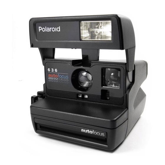
Page 7: General Description
640 Camera technology and has many derivative characteristics of the 630 and 635 Camera designs as well. The 636 offers automatic exposure control, fixed focus and rapid strobe recharge. Model 636 was introduced in worldwide and U.S. markets in 1992 and 1993, and offers users the following features: * Close-up lens for subjects 2 - 4 ft. - Page 8 Model 636 AF Autofocus Camera, from a service standpoint, is similar to the 636 OneStep/Close Up only in outward appearance. As an extension of the 636 Camera line, the 636 AF uses a slightly modified version of the Impulse shutter and a repackaged version of the Joshua electronics and software. It uses wink autofocus from two feet to infinity, a rapid recharge strobe with a range of 10 feet, and has a maximum shutter aperture of f/12.
-
Page 9: Sequence Of Operation
SECTION 2 - MODEL 636 SEQUENCE OF OPERATION Shown here is the location of the switches which regulate flash charging, flash fire and exposure. We will now run through a flash exposure sequence. Lightly pressing the exposure button closes the S10 contacts, charging the strobe main... - Page 10 Within five seconds the green LED at the rear of the strobe comes on, indicating that the main capacitor is fully charged. The picture taker may now press in the exposure button fully. This closes S1 and S10 remains closed. Closing S1 energizes the solenoid which pulls in slightly.
- Page 11 With the solenoid deenergized and the walking beam free of the shutter latch, spring- action opens the shutter blades. The internal clock is running and the photocell starts to measure light. In a fill-flash exposure, when the photocell sees 75% of the light needed for a proper exposure, it signals the flash to fire.
- Page 12 When the photocell sees 100% of the light needed for the exposure, the camera electronics orders the flash to quench and the solenoid to energize. The solenoid then pulls the blades closed. After the blades close, the motor is turned on, activating a gear drive system similar to the system in the OneStep.
- Page 13 The sequence for low-ambient conditions begins identically to the fill-flash sequence. The flash is charged via S10 and the shutter blades open the same way. However, the flash is fired by the internal clock reaching 74 ms, rather than by the photocell light measurement. This happens because there is relatively little light passing through to the photocell.
- Page 14 The camera determines whether the subject is NEAR or FAR by measuring the amount of light reflected back to the photocell 2 milliseconds after the flash has fired (76 ms into the exposure sequence). If the measurement is more than 50% of the total needed for a proper exposure, the camera decides the subject is NEAR.
- Page 15 After the blades close, the motor is turned on. The timing gear advances the pick, indexes the counter, and brings the S5 actuator back to its original position. The shutter system is latched closed, ending the low ambient NEAR sequence. If the light measured 2 milliseconds after the flash has fired is less than 50% of the total needed for a proper exposure, the camera decides the subject is FAR.
- Page 16 In a low-light FAR picture, the blades open fully and the photocell sees scene light through the photopic filter. When 100% of the necessary light is seen or when the internal clock reaches 396 ms, the flash is quenched and the shutter blades close. After the blades close, the motor is turned on.
- Page 17 For a non-flash picture (through a window), the exposure is started by pressing S1 only. The end-exposure command is given either when the photocell sees 100% of the necessary light for a proper exposure or when the internal clock reaches 396 ms.
- Page 18 Camera Operating/Exposure Sequence Diagram...
-
Page 19: Theory Of Operation
This is the Model 636 Camera which is one of a new line of 600 cameras. The Model 636 shares many of the features of the 635 and 640 Cameras. Among these are: Fixed Focus Lens, Electronic Shutter, Film Shade, Lighten/Darken Control, Empty Pack... - Page 20 One of the major differences between the Model 636 and the OneStep is the type of film it uses. Like all of the 600 line, the 636 uses a new film format. The film has a speed of 6O0 ASA.
- Page 21 On the other hand, a 600 film pack cannot be inserted into an SX-70 style camera since the tabs on the pack are held back by the older style pack springs. The battery in the 600 film pack has a higher capacity than the conventional SX-70 battery. It provides power for the shutter solenoid, the motor and for the built-in electronic flash.
- Page 22 When you open the camera, you can see another obvious difference between the Model 636 and the One Step — a built-in electronic flash. The flash is designed to be used for all pictures, both indoors and outdoors. The electronic flash features a rapid charge time of about 5 seconds. For outdoor pictures, the flash is used to provide a proportional fill-flash to eliminate objectionable shadows.
- Page 23 The flash is charged by lightly pressing the camera exposure button. The exposure mode is electronically inhibited until the flash is fully charged. When the green LED comes on, a picture can be taken by pressing the exposure button in all the way. An alternate way to charge the flash is to lightly press the exposure button.
- Page 24 The built-in flash is an electronic quench-type flash. It can provide a full output of about 340 zonal-lumen seconds (ZLS) to illuminate a scene or it can be shut down early to provide less light to the scene. The way the camera decides to provide full or partial light output will be discussed later.
- Page 25 Now, let’s talk about the way the camera logic decides when to fire the flash and how much light it needs from the flash before it quenches it. Refer to the Sequence of Operation section for a description of the order in which all of the events in an exposure cycle occur.
- Page 26 3 - In low ambient light with the subject far from the camera. Basically, the Model 636 uses either a light measurement alone to fire and shut down the flash, or a combination of light measurement and time measurement to fire and shut down...
- Page 27 After the flash is charged and the exposure button is pressed all the way in, three things happen simultaneously which decide how the flash is going to be controlled: 1 - The solenoid releases the shutter blades and they start to open; 2 - The photocell starts to measure scene light;...
- Page 28 Now, let’s go back to the three conditions in which a flash picture can be taken. The first is in high ambient light. In this condition, there is so much scene light available that the photocell always wins the race to fire the flash. This is the Fill Flash mode of operation. In the high ambient or Fill Flash mode, the photocell measures scene light.
- Page 29 At this point, the blades are still open and the exposure is being made. The photocell continues measuring light which now includes the light bouncing back from the flash. Next, the camera must decide when to shut down the flash and when to close the shutter blades. In the high ambient (Fill Flash) mode, the photocell makes the decision to shut down the flash and close the shutter blades.
- Page 30 The next condition in which a flash exposure can be made is in a low ambient condition (low light level, outdoor scenes and all indoor scenes). In this condition, there is so little light that the clock beats the photocell in the race to fire the flash. When the clock reaches 74 milliseconds (ms), the flash is fired.
- Page 31 The question is answered by measuring the amount of light seen by the photocell two milliseconds after flash fire. If the measurement is equal to or more than 50% of the light needed for a proper exposure, the camera senses subject is NEAR. If the measurement is less than 50% of the light needed for a proper exposure, the camera senses that the subject is FAR.
- Page 32 For NEAR subjects the logic instructs the clock to stop the exposure at 124 ms after the blades open. For FAR subjects the clock will time-out at 396 ms to stop the exposure. However, the ending of the exposure is also subject to the photocell light measurement. In other words, for a Low Ambient NEAR or FAR picture, there is still a race between the photocell and the clock to shut down the flash and close the blades.
- Page 33 In low ambient NEAR conditions, the flash will shut down and the blades close either when the photocell has seen 100% of the light necessary for a proper exposure or when the clock times-out at 124 ms. In low ambient FAR conditions, the flash will shut down and the blades close either when the photocell has seen 100% of the light necessary for a proper exposure or when the clock times-out at 396 ms.
- Page 34 The different clock settings for Low Ambient conditions are called the DUAL TIME-OUT SYSTEM. They allow long time-outs for distant, low-light scenes such as a sunset or an auditorium shot, or limit the length of the exposure for close-in scenes to minimize camera or subject motion.
- Page 35 In earlier cameras where a photocell was used to control the exposure, the photocell could be fooled into giving a reading which did not result in a good picture. This was especially true of flash pictures taken of subjects close to the camera. Light- colored clothing would reflect too much light to the photocell causing it to stop the exposure too soon.
- Page 36 This would result in a washed-out face. To overcome this problem, the Model 636 uses a photocell with a two-part filter in front of it, called a Dynamic Infrared Photometer system. The top half of the filter passes visible light which the human eye can see.
- Page 37 Now you may be wondering why infrared measurements greatly reduce over- or under- exposures in close-up flash pictures. This chart shows the light spectrum. In the infrared region of the spectrum, a strange phenomenon occurs. The light reflected off just about all materials is equal. Therefore, the light passing through the infrared filter is balanced, preventing the photocell from being fooled by contrasting levels of light or dark subject matter.
- Page 38 For Fill Flash pictures, the shutter blades open as shown here. The blades are set so only visible light passes through the first photopic aperture to the photocell. Thus, for Fill Flash, exposure shutdown is based on the measurement of visible light only. In a low light NEAR shot, the blades travel farther.
- Page 39 For low light FAR pictures, the blades travel even farther. First, there is a very small amount of light passed through the first photopic aperture. Next, a very small amount of light passes through the infrared aperture. Finally, the blades open fully and a large amount of visible light passes through the second photopic aperture.
- Page 40 The dark slide cycle is the same as in Pronto! type cameras. When a fresh pack is loaded and the front door closed, S1 and S9 are closed and the solenoid energized. The S5 actuator drops, closing S5L and S5P, turning on the motor. The dark slide is ejected and the counter set to 10.
- Page 41 NO S1 There are two mechanical inhibits. When the counter reaches its blank setting, S1 is prevented from closing. This is the same as the empty pack lockout feature on Pronto! cameras. Finally, when the camera is in the folded position, S10 is mechanically locked open by a tab on the flash housing.
-
Page 42: Table Of Contents
Tweezers and dental pick Disassembly Note No screws or threaded fasteners are used in the 636 Camera: most housings and piece parts of sub-assemblies are held in position by detents, spring catches or tangs which engage bosses or cutouts in corresponding mating parts. Careful “spring apart” techniques will free most parts of the 636. -
Page 43: Strobe Disassembly
Strobe Disassembly... - Page 44 Remove Strobe Cover using removal tool 12633. Insert tool in hole on right side underside of Housing and tilt bottom of tool to the right (CCW) to release molded catch inside cover (A in Fig. 1). Repeat process on left side, tilting bottom of tool to the left.
- Page 45 With Strobe tilted downward at a 45-degree angle, remove Lower Housing Assembly using a soldering aid tool (greenstick). Carefully spring out sides as shown in Fig. 3 (Flex remains connected to Lower Housing). Fig. 3 Removing Lower Housing Remove two Flex leads from PC Board by inserting appropriate-size fingers of Universal Flex Tool 12601 into Board connectors and pulling Flex out (Fig.
- Page 46 Remove Flashtube Assembly from the Lower Housing by gently pushing in along top edge of Flash Shield (Fig. 5). Remove Insulator, and unsnap catches on ends of Flash Shield to remove it from Flashtube Assembly. Fig. 5 Removing Flashtube Assembly, Flash Shield and Insulator If it is necessary to remove the Flashtube itself, unsolder the three leads from the Capacitor, PC Board and Trigger Coil (Fig.
-
Page 47: Strobe Reassembly
Remove the PC Board by lifting it straight up off the molded post on the Lower Housing (Fig. 7), being careful not to lose the small S10 Plunger from the base of the Lower Housing. Set Plunger aside. Fig. 7 Removing PC Board & Flashtube Assembly & Plunger Strobe Reassembly Replace the parts removed in the preceding Steps 1 - 7, in this order: Flash Shield... -
Page 48: Apron Disassembly
Apron Disassembly... - Page 49 Open the Film Door to remove the Apron. Insert a soldering aid, first at position A and then B (Fig. 8), to free the Body detent lugs from the Apron. Carefully “lever” the Apron out of the Body. Repeat the process on the opposite side. The S1 Button and S10 Button with Return Spring will fall out.
-
Page 50: Close Up Lens Disassembly
Disassemble the Close Up Lens, wearing finger cots or lintless gloves. First, remove the Spring with tweezers (Fig. 10). Next, slide the Shuttle to the left and lift its left end to remove. Now slide the Close Up Lens to the right and with a green-stick under the right end, carefully lift the Lens until the top edge clears the detent on the Panel. -
Page 51: Close Up Lens Reassembly
Reassembling the Close Up Lens & Trim Button Wearing finger cots or lintless gloves to keep the Lens elements free of smudges, first engage the “foot” at the bottom right corner of the Lens with the Panel (see Fig. 11). Then slide the Lens to the left slightly and gently press down until it engages in its guides. -
Page 52: Body Disassembly
Body Disassembly... - Page 53 To remove the Cone, insert a flat blade screwdriver at the locations shown in Fig. 13, springing out the sides of the Body slightly. This frees the Cone from the catches inside the Body. Lever the Cone forward, out of the Camera Body. The freed Release Button will drop out.
-
Page 54: Body Reassembly
Remove the Pack Spring by depressing it with your thumb and pulling it forward, out of the Body (Fig. 15). (If the Camera has a Tripod Nut, it will now fall out.) Fig. 15 Removing Pack Spring and if present, Tripod Nut To Remove the Eyecup/Retainer (one unit), from inside the Body depress either pair of the four tabs shown in Fig. -
Page 55: Shutter Disassembly
Shutter Disassembly... - Page 56 Mount the Cone on a universal swivel fixture. Remove Viewfinder Housing by tilting rear end upward (Fig. 17) and rotating it forward (note position of the tab at its left front). Fig. 17 Removing Viewfinder Housing With tweezers, remove Opening Blade Spring from rack and Base Block (Fig. 18), first noting which notch on the rack it’s attached to and marking that notch to assure correct reassembly later.
- Page 57 Remove Ambient Calibration Disk by depressing tang at bottom (Fig. 19). Remove IR Calibration Wedge, IR Lens Filter and Ambient Lens (Photopic) Filter from the Lens Mounting Plate (Fig. 19). Fig. 19 Removing Ambient Calibration Disk, IR Calibration Wedge, IR Lens Filter & Ambient Lens Filter Remove Lens Mounting Plate by releasing the three tangs along the bottom edge, which fastens it to the Shutter Base Block (see Fig.
- Page 58 Remove Inertia and Walking Beam as an assembly, keeping Inertia Spring in place (Fig. 21). Wearing finger cots or lintless gloves, remove Shutter Latch and Shutter Blades (keep blades in the same relative positions and order in which they were removed). See Fig.
- Page 59 Using Universal Flex Removal Tool, remove Flex from Contact Support Block and Motor (Fig. 23). Now lift Wire Block Assembly off the Cone and remove the Flex from the Wire Block (Fig. 23). Fig. 23 Removing Flex from Contact Support Block, Motor and Wire Block Remove the Base Block from the Cone by releasing the two locking tangs near Motor and Counter Wheel (see Fig.
- Page 60 With Flex Removal Tool, disconnect Flex from the Solenoid connector (Fig. 25), then lift Flex up and out from under the connector block. With point of soldering aid, carefully free the Photocell (attached to the Flex) from its mounting on the Base Block (see Fig.
-
Page 61: Shutter Reassembly
Shutter Reassembly Replace the Solenoid with its Plunger in place into the Base Block. The notch and guide pin on the Plunger yoke must face the rear of the Base Block (see Fig. 27), so that the yoke pin rides freely in the Base Block slot. Fig. - Page 62 Remount the Base Block on the Cone by positioning the two openings at the top of the Base Block over the corresponding projections on the Cone (see Fig. 29), then rotating the Base Block down into position until the locking tangs near the Counter Wheel and Motor snap shut.
- Page 63 Reassemble the Shutter blades by inserting a dowel pin 3/32" x 3/4" (2.4 x 19 mm) in the hole in the Base Block shown in Fig. 31. Wearing finger cots or lintless gloves, install the bottom, middle and top Shutter Blades over the 3/32" dowel pin, and with the molded pin on Base Block projecting up through the slot in Blades (Fig.
- Page 64 Replace the Inertia and Walking Beam Assembly by engaging the four pins in the Blades, Solenoid Plunger Yoke and Base Block pivot point (see Fig. 33). Carefully remove the dowel pin and test Shutter Blade operation by moving the Walking Beam Assembly to produce an aperture.
- Page 65 Replace the Lens Mounting Plate by placing the two tabs at the top into their corresponding openings in the Base Block (Fig. 35). Tilt the Plate down- ward into position, making sure the Inertia pivot post enters its hole in the Base Block. Snap the three locking tangs closed at the bottom of the Plate.
- Page 66 Replace the photometrics in this order, as shown in Fig. 37: Ambient Lens Filter (green), Infrared Lens Filter, IR Calibration Wedge over the pivot on the IR Filter Lens, and the Ambient Calibration Disk with the stops on the bottom. Fig.
-
Page 67: Drive Disassembly
Drive Disassembly... - Page 68 If necessary, remove the S1 Leaf Spring from the Gear Drive Cover by pulling it forward slightly and then lifting it up (see Fig. 39). Disconnect the red jumper wire from the S10 movable contact by depressing the spring finger to release it (Fig. 39). Move the wire out of the way. If necessary, remove the S10 movable contact.
- Page 69 Release the tension on the Counter and Pawl Springs (see insets A and B, Fig. 40). Release the Drive Cover forward detent (inset C), the hanger detent (inset D) and the rear detent (inset E). NOTE: In step 49, the metal gear (#5) may become dislodged. Be careful that it is not lost. Fig.
- Page 70 Refer to Fig. 41: place your thumb over the left end of the Gear Drive. Slowly and carefully lift the right end of the Cover. Remove the Cover by walking the left end free of its detent. Use care to not break the detent. Fig.
- Page 71 Remove the Counter and Counter Spring by pulling the Counter off its shaft (Fig. 43). Remove the four remaining Gears and the Spacer from their shafts (Fig. 43). Release the back end of the Pick Return Spring and slide the Pick forward. Lift both parts free of the Cone Assembly (Fig.
-
Page 72: Drive Reassembly
Drive Reassembly Install the S5 Actuator on the Slider. Hold them together while installing them on the Cone. Install the Slider Assembly over the pivot on the housing (Fig. 45). Be sure the tip of the S5 Actuator is over the Shutter Latch (see Fig. 45). Fig. - Page 73 Using Fig. 47 as a guide, replace the four plastic gears, metal gear #5 and the spacer. Fig. 47 Gear placement guide Referring to Fig. 48, replace the Door Pawl and Pawl Spring. Fig. 48 Replacing Door Pawl and Spring...
- Page 74 Set the Counter Spring into the Counter (Fig. 49), wind the Spring, push in the Slider and place the Counter on its shaft. Temporarily hook the Spring onto the lower detent. (Note that the number 6 is upside down and facing forward.) Release the Slider: the Counter should lock into place and the number 7 drop so it is facing forward (upside down).
- Page 75 Install the Timing Gear on its shaft (Fig. 51). It may be installed in any position as long as none of its cams interfere with the motion of the Pick. (The camera will time itself in its first cycle.) Fig. 51 Replacing the Timing Gear Replace the Gear Drive Cover (see Fig.
- Page 76 Replace any Contacts and parts removed from the Gear Drive Cover in steps 43 - 47. Reconnect the (+) battery wire to the S10 fixed contact and the Contact Support Block, and the red jumper wire to the S10 movable contact (see Fig. 53). To wire block S1 Leaf...
-
Page 77: Door/Spread Sys. Disassembly
Door and Spread System Disassembly Remove the Door Assembly by disengaging the hinge on the right side (opposite gears), then the hinge on the left side. Remove the Spread System Assembly by inserting an Exacto knife with a #11 blade just below the lower leg of the spring, on the left (non-gear) side (see Fig. -
Page 78: Reassembly Completion
To complete the reassembly of the Camera: Replace the Viewfinder on the Cone Replace the Cone into the Body Replace the S1 and S10 Buttons Replace the Release Button Replace the Apron to retain the Release Button... - Page 79 [This page intentionally blank]...
- Page 80 [This page intentionally blank]...
-
Page 81: Troubleshooting
Before performing the troubleshooting procedures presented in this section, you should be thoroughly familiar with the Theory/Sequence portion of this manual. Quite obviously you must know how the 636 Camera works before you can start to diagnose its problems. Initial Inspection The following procedure should be done before you get involved in an operational check of the 636 Camera. - Page 82 - Cone filler #550851A is in position or cone has molded fix (See RIB 600AM #6). 3. Functional Test Perform the following functional test on the 636 camera using film pack simulator #12467 (.3 ohms) and power supply Power Mate #12531 or Lambda #12429.
- Page 83 2. Test Open the front door of the camera and install the film pack simulator. The camera should not cycle. Remove the film pack simulator and install door pawl closure #12082. Install the film pack simulator again: - The camera should go through the dark slide cycle. - The shutter blades should remain closed.
- Page 84 Remove the film pack simulator and door pawl closure: - the counter will return to its starting position. Insert a known good film pack with film into the camera. Take a 2-foot cyan background picture with strobe: - observe that the film transport and delivery systems are functioning properly. - observe the finished picture for complete coverage.
-
Page 85: Troubleshooting Charts
TROUBLESHOOTING CHARTS (NOTE: Also see the RIB and Product Alert listing following these charts) PROBLEM PROBABLE CAUSE CORRECTIVE ACTION Dark Slide Cycle 1. Door pawl spring defec- 1. Replace spring with Front Door Open tive or not loaded or load spring (Non-Continuous) (If under pack pawl. - Page 86 PROBLEM PROBABLE CAUSE CORRECTIVE ACTION No Dark Slide Cycle 9. Battery contact height 9. Replace battery (cont’d) marginal or not seated contacts. properly. 10.Flex circuit defective. 10.Replace flex circuit No S1 response 1. Defective S-1 button 1. Replace S1 button or S-l slider.
- Page 87 PROBLEM PROBABLE CAUSE CORRECTIVE ACTION Continuous Cycle 7. Counter spring unwound 7. Install counter (cont’d.) or not trapped in spring correctly counter properly 8. S-1 slider cam interface 8. Install S1 slider with counter not correct cam properly. 9. S5 P&L contacts under 9.
- Page 88 PROBLEM PROBABLE CAUSE CORRECTIVE ACTION High Current Drain NOTE: First determine whether problem is with strobe or camera. Replace strobe with known good test strobe. If operation is OK with test strobe, problem is in original strobe which must be replaced.
- Page 89 PROBLEM PROBABLE CAUSE CORRECTIVE ACTION LED does not light NOTE: If strobe does not function, see Strobe Failures. 1. LED shorted at PC board. 1. Correct short. 2. LED not installed 2. Install LED properly. properly on PC board. 3. LED defective. 3.
- Page 90 Additional 600-line Camera Troubleshooting help from Product Alerts and RIBs NOTE: Many of the problems and fixes described below were temporary solutions, later permanently corrected by design/manufacturing changes. Thus the repair material described below may or may not be present in or applicable to a later version of the camera.
- Page 91 SECTION 6 — 636 CAMERA TESTING WITH THE STAR TESTER CONTENTS Page A. Test Specifications for Model 636 Camera B. Graywall Preparation C. Setting Up the Model 12650-2 Star Tester D. Star Tester Controls and Indicators E. Testing the Model 636 Camera: 1.
-
Page 92: Test Specifications For Model 636 Camera
A. Test Specifications for Model 636 Camera Test: Specification: Flash Timing 2.0 to 13.0 ms Ambient Exposure -0.30 to +0.10 Strobe Exposure (Graywall) 0.0 to -0.50 ZLS Output 260 to 400 ZLS Charge Time (2nd cycle) 4 sec. max Energy Draw (2nd cycle) 12.5 amp sec. - Page 93 Secure the graywall target to the wall and set up the test equipment as instructed in the setup procedures. The center of the target must be aligned with the taking lens of the camera under test. 4 ft (1.2 m) 4 ft (1.2 m) 4 ft...
-
Page 94: Setting Up The Model 12650-2 Star Tester
C. Setting up the Model 12650-2 Star Tester Install the Star Tester on a level surface with sufficient clearance to allow proper air flow for the cooling fan and exhaust vents. Also, the tester work surface should be located so the various fixtures can be located 4.5 feet (137 cm) from a graywall target. -
Page 95: Aligning Camera On Horn With Tester Window
Erect the electronic flash of the Model 636 and place the camera on the Star Horn #12625. Set the horn with the mounted camera against the tester. Using the leveling legs, raise or lower the tester so that the electronic flash is aligned with and fits into the adapter window (Figure 3). - Page 96 Remove the horn with mounted camera from the proximity of the tester. Carefully, tilt the tester and install two risers #12885 under the leveling legs. Tilt the other side of the tester and install two more risers under the two remaining leveling legs (Figure 4). Risers #12885 Fig.
-
Page 97: Test Setup And Horn Riser Position
Place horn riser #12884 under the star tester horn (see Fig. 5). Set the horn in the lowered position (Fig. 5). Horn riser #12884 Horn in lowered position Fig. 5 Test setup and Horn Riser position for Model 636... -
Page 98: Star Tester Controls And Indicators
The Star Tester #12650-2 is used to check exposure and timing related parameters of Polaroid cameras. This section deals exclusively with the 636 Polaroid Camera. The light box and the electronics required to compute and display exposure, timing and functional test measurements are housed in a single chassis (see Fig. - Page 99 Simulator, allowing Tester to be used as a power supply. Strobe Adapter Aligns electronic flash of camera under test to Tester. No. 12657B used for 636 Camera Horn Connector Provides the electronic inter- face for the Star Tester Horn. Disc Detector Not used with 636.
- Page 100 Fig. 6 Star Tester Controls and Indicators...
-
Page 101: Testing The Model 636 Camera
Tester to be certain there is sufficient air flow for proper cooling of the elec- tronics. Turn the Tester ON and observe that the power-on lamp is illuminated. 2. Order of Tests It is very important that the Model 636 Camera tests be done in this order: 1. Flash Timing 2. Ambient Exposure 3. - Page 102 Model 636 Camera Test Procedures (in the order in which they should be performed). Model 636 Flash Timing This test determines if the proper infrared sensing is accomplished during a strobe exposure. The time between shutter blades being 95% fully open and strobe fire is measured and displayed in milliseconds.
- Page 103 Model 636 Ambient Exposure This test measures the energy on the film plane during an ambient exposure. The Tester provides a constant 100 candles/square foot scene brightness. NOTE: The following procedure assumes the Tester is on and the camera is installed on the horn in front of the Tester light source.
-
Page 104: Setup For 636 Graywall Test
If the reading is not within 6. If reading out-of-spec, see specification, refer to the Adjustments. Adjustment section. Horn must be located so 4.5 ft camera taking lens is (135 cm) 4.5 feet (135 cm) from graywall Fig. 7 Setup for 636 Graywall Test... - Page 105 Model 636 Zonal Lumen Seconds (ZLS) Output This test measures the output of the strobe in a standard integrating sphere located within the Tester. The light output measurement is integrated over the duration of the flash and the measurement is displayed as correlated zonal lumen seconds on a meter on the Tester.
-
Page 106: Camera Adjustments (Correcting Out-Of-Spec Test Results)
F. Camera Adjustments (correcting out-of-spec test results) This section describes adjustments which can be made to correct readings which are out-of-specification on the Star Tester #12650-2. Refer to the Specification Chart to determine acceptable readings for each of the tests listed below. 1. -
Page 107: Ambient Exposure
2. Ambient Exposure With the Camera off the Tester, remove the Front Plate/Lens Panel and replace it with a modified Front Plate as shown in Fig. 10. (See NPI 600AM #92-30 for more information.) Using a dental pick, narrow-bladed screwdriver or other suitable tool, adjust the ambient calibration disc. -
Page 108: Strobe Exposure
3. Strobe Exposure (Graywall) NOTE: If the Strobe Exposure readings are out of spec, perform the ZLS Output test before making the adjustment below. If ZLS reading is out, replace the strobe With the Camera off the Tester, remove the Front Plate/Lens Panel and replace it with a modified Front Plate as shown in Fig. - Page 109 - NOTES -...
- Page 110 - NOTES -...
-
Page 111: Calibrating The Model 12650-2 Star Tester
Any re-calibration must be done in the order shown. See your calibrator box specification sheet for actual readings. Allow a minimum of 10 minutes of “warm-up” time before checking calibration. NOTE: * = Applicable to Model 636 Camera SUMMARY Manual... - Page 112 SECTION 7 — 636 CAMERA TESTING WITH THE B-600 TESTER CONTENTS Page A. B-600 Tester functions, controls & indicators B. Model 636 Camera Testing: 1. Camera Test Specifications 2. Pretest Procedures 3. Test Procedures: a. Flash Timing Aperture b. Flash Exposure c.
-
Page 113: Tester Functions, Controls & Indicators
Once you have become familiar with the test procedures, occasional reference to the summary should be all that is necessary to properly test 636 cameras. CONTROL/INDICATOR... - Page 114 Fig. 1 Model B-600 Tester and Model B Light Source...
-
Page 115: Model 636 Camera Testing
B. Model 636 Camera Testing 1. 636 Camera Test Specifications Test Specification Flash Timing Aperture -.02 to +.07 Flash Exposure -.15 to -.55 Ambient Exposure +.10 to -.30 2. Pretest Procedures Before performing any of the tests below, examine the B-600 testing system. Check the electrical connections between the electronic unit, the light source and the horn to be sure they are properly made. -
Page 116: Test Procedures
3. Test Procedures: Model 636 Flash Timing Aperture The purpose of this test is to measure blade aperture at the point of flash fire. DETAILED PROCEDURE SUMMARY 1. Turn the test selector switch to Selector to FT and BB Ft and BB APERTURE. -
Page 117: Camera On Horn, Ready For Testing
Strobe detector clip Camera electronic flash Fig. 2 Camera on Horn, ready for testing... - Page 118 Model 636 Flash Exposure This test measures the resultant energy on the film plane during a flash exposure equivalent to a 4.5 ft graywall exposure. NOTE: The following procedure assumes the camera is on the horn. DETAILED PROCEDURE SUMMARY 1. Set the camera L/D control to its Camera L/D to mid-point mid-point setting.
- Page 119 Model 636 Ambient Exposure This test measure the energy on the film plane during an ambient exposure at 100 cd/sq ft scene brightness. NOTE: The following test assumes the camera is on the horn, against the light source. DETAILED PROCEDURE SUMMARY 1.
-
Page 120: Flash Timing Aperture
C. Model 636 Camera Adjustments (to correct out-of-spec test results) This section describes adjustments which can be made to correct readings which are out-of- specification on the B-600 Tester. Refer to the latest Specification Chart to determine acceptable readings for each of the tests listed below. -
Page 121: Removing Front Plate/Lens Panel
1. Model 636 Flash Timing Aperture Adjustment Remove the Front Plate/Lens Panel from the apron (Fig. 3). Using tweezers, grasp the end of the opening blade spring. Move the opening blade spring up in the rack to increase the reading or down in the rack to decrease the reading (Fig. -
Page 122: Adjusting Ir Calibration Wedge
2. Model 636 Flash Exposure Adjustment Remove the Front Plate/Lens Panel (see Fig. 3) and replace it with the modified Front Plate shown in Fig. 5 (NPI 600AM #92-30 has more information). Using a dental pick, narrow-bladed screwdriver or other suitable tool, adjust the IR calibration wedge (see Fig. - Page 123 3. Model 636 Ambient Exposure Adjustment Remove the Front Plate/Lens Panel (see Fig. 3) and replace it with the modified Front Plate shown in Fig. 5 (NPI 600AM #92-30 has more information). Using a dental pick, narrow-bladed screwdriver or other suitable tool, adjust the ambient calibration disc (see Fig.
-
Page 124: Calibrating The B-600 Tester
D. Calibrating the B-600 Tester Calibration of the B-600 Tester is done in three steps: (1) calibrating the Light Source, (2) the Horn and (3) the Electronics Unit. While the probability of the B-600 going out of calibration is unlikely, the B-600 should be checked daily. - Page 125 If this is not the case, the light level must be adjusted. Remember that adjusting the light level also affects the visible/IR ratio. Also, increasing the lamp voltage causes the IR level to drop. When the 100 cd/sq ft level is correct and the ratio acceptable, calibrate the remaining light levels as follows: slide the blade control all the way to the right and adjust the correspond- ing detent block on the front of the Light Source.
- Page 126 Calibrating the Electronics Unit Plug the calibrator into the Horn Connector. Set the CAL/TEST Switch to CAL. Set the two switches on the Calibrator in the AMB and CONT positions. Starting with the 75 exp. range, set the Range Switch on the Electronics Unit and the rotary switch on the Calibrator to the positions shown on the label on the rear of the Calibrator.
Need help?
Do you have a question about the 636 and is the answer not in the manual?
Questions and answers