Table of Contents
Advertisement
Advertisement
Table of Contents

Related Manuals for µ-Dimension Glow DSP8

Summary of Contents for µ-Dimension Glow DSP8
-
Page 2: Table Of Contents
Table of Contents- Section 1 - Installation Installation Considerations - Page 3 DSP8 Hardware Identification- Page 6 Input Port & Features - Page 7 Speaker level/OEM Integration Page 8 Signal Input Harness - Page 9 Speaker Output Harness & Port - Page 10 Section 2 - Getting started (Software, Firmware updates and more) -
Page 3: Installation Instructions
Considerations Thank you for purchasing the DSP8 reference digital amplifier system with integrated DSP technology. The DSP8 is a state of the art 8 channel digital amplifier system with a first of its kind full open architecture digital sound processor available for the car audio market. -
Page 4: Installation Considerations
To Ensure proper operation of your new purchase, please follow the instructions and suggestions located throughout this manual. Before You Begin Please check the suitability of the installation before you begin. Do not cut an portion of the cars structure. Pay close attention to what is behind the vehicles panels or carpeted area you are considering to mount your newly purchased product. - Page 5 If the voltage of your vehicles charging system drops too low even the most expensive of audiophile rated amplifiers will drop below their rated output. Make sure your charging system is in good working order. If you are unsure if your charging system is working properly have it tested by a qualified professional technician or take it to a certified authorized dealership.
-
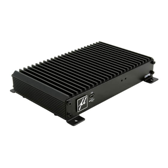
Page 8: Input Port & Features
DSP8 Input Harness Port- Because of the wide range of head units used in vehicles worldwide, both OEM and aftermarket the DSP-8 has one of the most flexible input configurations available. This section will cover a variety of applications and the information needed to connect the DSP8 into your vehicle. -
Page 9: Speaker Level/Oem Integration
DSP8 Signal Input (High Level/Speaker Level) If your installation requires the continued use of your factory radio the DSP8 has a flexiable “Manual Set” Hi Level/Low Level input stage. To achieve this opration you will be required to open up the bottom of the DSP8 and configure the intrnal jumpers as directed below. -
Page 10: Signal Input Harness
DSP8 Input Harness Pin 1 - (Brown Wire) Profile 2 lead wire (NOT USED) Pin 2 - (Red Wire) Profile 1 Lead Pin 3 - Channel 6 RCA + Pin 4 - Channel 5 RCA + Pin 5- Channel 4 RCA + Pin 6- Channel 3 RCA + Pin 7-... -
Page 11: Speaker Output Harness & Port
DSP8 Output Speaker Harness Port Balanced RCA Output Pin 1- (Grey) Channel 8 + Pin 2- (Violet) Channel 7 + Pin 3- (Blue) Channel 6 + Pin 4- (Green) Channel 5 + Pin 5- (Yellow) Channel 4 + Pin 6- (Orange) Channel 3 + Pin 7- (Red) Channel 2 +... -
Page 12: Connecting To Your Pc
Connecting to your PC Now that you have installed your DSP8 into your vehicle it is time to start setting up your system. After you load the DSP8 software to your computer you will connect your PC to the DSP8. The DSP8 software is compatible with 32Bit and 64 Bit computers running the Windows XP, Wndows Vista and Windows 7 operating platforms. -
Page 13: Getting To Your User Interface
Getting to know your User Interface USB Connection Status Windows Panel USB/DSP Process Indicator Master Gain Feature Tabs Control Active Information Area Channel Mute Panel Profile Selection Software/Firmware Version Indicator Amplifier Internal Temp. Indicator Tuning Features- - Arrow key adjustment on most adjustable tuning features - Real time interaction between DSP and PC - Onboard real time digital signal meters for precise signal alignment for most any application (includes input signal, dsp output, amp-... - Page 14 Windows Panel - Firmware Update Panel, PC Database access for saving tunes or loading user made custom tunes Selection tabs to access each of the DSP8’s high Feature Tabs- resolution tuning features Displays all adjustable controls and settings of the Active Info Panel- current project in use.
-
Page 15: Synchronizing Your Pc To The Dsp8
Synchronizing your PC to the DSP In order to make accurate changes in the custom tune menu’s of the DSP8 you must first make sure that the PC and DSP is reflective of the actual settings between the components. Every time you start to connect your computer to the DSP8 you will be prompted to select a Sync direction ensuring that from the very first adjustment your adjustment are properly reflected on your user utility. -
Page 16: Saving And Retrieving Setup Files
Saving + Retrieving Setup Files with your PC The advantage to using a PC based sound processor is that you are not limited to the presets available on the user utility. The DSP8 incorporates a multi tiered file management system that enables the user to save thousands of complete setup files on his/her hard drive. -
Page 17: Password Protection And File Security
Password Protection and File Security To achieve a world class sounding audio system you need a world class tune. These tunes can take many hours if not days or even weeks occupying many hours of time invested to create that personalized musical experience. - Page 18 Restoring the system to factory default- If you have lost or forgotten your password and wish to erase and clear the set encrypted security feature from your DSP the only way to achieve this is to reset the DSP to factory default settings. Please be reminded that doing this will clear the entire DSP and you will loose all custom settings stored on the DSP.
-
Page 19: Firmware Updates
Firmware Update From time to time you as we improve the hidden technology with the DSP you may be required to update the systems with the latest and greatest firmware update. Your user interface is designed with a trouble free simple operation updater that will allow you to update the firmware without ever having to download, transfer, save, or log into any difficult to access website to update your DSP. - Page 20 Step 3 - Next a new window will pop up advising you that upon completion of the firmware update you will have to power cycle (Power off and then back on) to fully update the system. Click “OK” Step 4 - Once you have accepted the requirement to power cycle the ce you have accepted the requirement to power cycle the DSP8 you will be prompted with a pop-up window indicating...
-
Page 21: Manually Installing Usb Boot Loader
Manually Installing the USB Boot Loader When you install your user software and fire up the DSP8 for the first time we recommend that you update the firmware before making your initial settings. Rest assured your DSP8 is current ready to be installed in your vehicle but this process makes sure your DSP8 is up to date with any updates that may of occurred while in transit from the factory to your authorized retailer. - Page 22 At this point with your firmware update tool open your computer has already identified the inability to make the appropriate connection and will read the processor as missing the required driver for this application. Step 2 - Cick on your Windows Desktop “START” button and proceed to the control panel menu on your operating system.
- Page 23 Step 4 - After right clicking on “unknown device” select the option listed as “update driver software”. Once this option has been selected you will be prompted to search for the driver software. Select the option highlighted below listed as “Browse my computer for driver software” Step 5 - You will now be directed to a file browser panel.
- Page 24 STEP 6- Y ou will be prompted with a map of your computers database. Take note that you will be loading an entire folder named “JM60 USB Drivers” and not the files in the folder. You will find the required driver folder in the following location. 32bit operating systems - C:\Program Files\Nikola\DSP8 64bit operating systems - C:\Program Files (x86)\Nikola\DSP8 SELECT THE ENTIRE FOLDER..
- Page 25 Step 7- With the JM60 Folder selected click “OK” and then on update screen you will see the address for the correctly selected file in the location window. Now Click “Next”. After clicking next you will be prompted for authorization to give permissions to install the new driver.
-
Page 26: Other Controls
Other Controls Channel Muting- Full time individual channel muting is available on your user utility no matter what settings screen you might be in allowing you to mute one or multiple channels at any time. Simply hover your mouse indicator above the desired channel and click on the check box to mute or unmute the channel Master Gain- The DSP8 master gain is not an input sensitivity... -
Page 27: V.u. Meters
V.U. Meters The DSP8 microprocessor has an advanced diagnostics and signal monitoring system built into the user interface allowing the user to monitor and test the individual settings of each channel at different spots thru the audio path within the DSP and the signal passing thru it. V.U. - Page 28 Internal V.U. Meter - Used to verify mixer configu- ration and level settings. - Confirms channel assignment and signal levels into the crossover section of the DSP DSP Output V.U. Meter - Monitors dynamic signal levels post DSP going into the amplifier stage of the DSP8 - Warns user of possible speaker damaging distortion...
-
Page 29: Section 3 - Tuning Your System
Section 3 - Tuning Your System Intro- This manual is designed to familiarize the reader with some very important system tuning concepts and considerations. It will not give specific control adjustment details related to the specific inputs, outputs, and controls incorporated in the Arc Audio DSP8, but rather will cover more of a broad, overall theory for tuning your audio system, helping you to formulate a game plan in you approach towards the specific design and tuning of your audio... -
Page 30: Inital Considerations
Initial Considerations 1) What it takes to make a system sound the best One thing that is absolutely essential to understand is that simply installing high quality audio gear does not ensure that the system will sound great. Sure, it is essential to use high quality equipment, and the DSP8 with its tremendously capable features will make your job a lot easier. - Page 31 On the other hand, an ultra-performance competition system will require the use of every control available in the DSP8, and each control may be adjusted many times during the fine tuning process in order to get the system dialed in for the very best performance. 2) Know and Understand the Equipment Make sure you’re familiar with all of the features of the system components you’ll be using.
- Page 32 4. Listen, Listen, Listen Always listen to the changes you are making to the system tuning after each adjustment, or short series of adjustments. If the changes are not improving the sound quality, don’t be afraid to back up and try something different.
-
Page 33: System Tuning Functions
System Tuning Functions Input and Output Level Setting- To ensure the highest overall audio system signal-to-noise ratio and dynamic range performance, the signal level controls on every component in the system should be set so that the highest possible un-distorted signal levels are maintained at every step in the signal chain, from the signal source through every component, including the amplifiers. -
Page 34: Input Mixer And Polarity Setting
Input Mixer and Polarity The DSP8’s input mixer can allow you to do several key things in regards to optimizing system sound quality that can not be done as easily, if at all, in other ways and/or with other types of signal proces- sors. -
Page 35: Operating The Mixer
The use of an RTA is the easiest way to confirm proper channel combination(s) thru a mixer. This technique can give you a quick visual indication of the signal frequency response, using pink noise as the source signal and connecting the DSP8 output to the RTA line level input. -
Page 36: Initial Settings And Tuning
Initial Settings and Tuning This chapter will get you started on system tuning. The key here is to set everything in the DSP8 so that the speakers are protected from frequencies that could damage them, the gain structure and signal levels are optimized to ensure maximum signal levels, and everything is set to be neutral within the crossover, EQ, and delay sections. -
Page 37: Output Level Settings
Output Levels Before adjusting the output levels, make sure the EQ is bypassed temporarily. You must also use an appropriate frequency test tone for each output. Remember that the crossover will limit the frequency response to the frequency range above the high- pass frequency setting, and/or below the low-pass frequency setting for each output channel. - Page 38 As you adjust the system for relative levels between the subs, midranges, tweeters, etc, you may need to reduce some outputs relative to others. Remember that you have set the levels to their absolute maximum possible with minimal clipping/distortion, so any additional level changes, whether it is in the equalizer or an input or output level, needs to be a reduction in level.
-
Page 39: Initial Eq Settings
Initial EQ Settings If the signal source is an aftermarket unit, you can usually assume that the signal output frequency response is flat throughout its frequency range, and no initial EQ adjustments will be required at this point. However, make sure all equalizer controls and loudness compensation are turned off. - Page 40 more EQ adjustments to the system later to compensate for acousti- cal correction necessary to optimize the desired sound quality, but we want to start with a clean, smooth signal during initial system setup. So, when the RTA is connected to the processor outputs to confirm the proper utilization of the mixer for re-combining channels, you can also verify and correct the initial frequency response if needed.
- Page 41 caused by a cancellation in the response. This can be due to multiple speakers playing the same frequency but having them out of phase at the microphone location. It could be caused by a reflection off a hard surface, where the direct sound arrival from the speaker and the reflected sound off the hard surface arriving slightly later combine to cancel the response at that frequency.
-
Page 42: Initial Crossover Settings
Initial Crossover Setting The initial crossover setup step is really basic. All of your initial crossover settings can be fine tuned later. Right now, you just want to set the crossovers to protect the speakers, and be within the designed operational frequency range for each. You will make more detailed, fine-tuning adjustments later. - Page 43 combination of listening to the system while adjusting the crossover, and looking at the response on an acoustical analyzer (RTA or other measurement system). In general, a dedicated mid-bass driver’s upper frequency limit will be between 125 and 250 Hz. If there is no dedicated mid-bass speakers being used, then set the crossover between the subwoofer and the midrange outputs to the lowest frequency the midrange is capable of reproducing...
-
Page 44: Initial Signal Delay Settings
Initial Signal Delay / Speaker Polarity When getting started, we recommend that the speaker outputs polarities all be set in polarity. It is just a good starting point from which you will fine tune later. As for signal delay, you can look at the physical relationship between the different speakers and make rough approximations to initially set delay. - Page 45 Adjusting the actual signal delay can be accomplished in several manners, similar to adjusting equalization. Often, the processor manufacturer’s instructions will provide a good set of guidelines to follow when tweaking their products. What will be presented here are general guidelines and considerations to make the job easier. The tools you can use to help tweak the signal delay include all of the frequency response measuring tools;...
- Page 46 determine which speaker is the furthest from the listener’s ears. For single seat SQ system designs, this will be done for all speakers in the system relative to the single speaker furthest from the driver’s head location. For multiple seat SQ system designs, you will do this for each channel of the system independent of the other channels.
- Page 47 on that channel, start with the delays on the two speakers in the lowest frequency ranges (i.e. mid-bass and midrange), and work up in frequency through the delays. When the first channel sounds as good as possible by itself, move on to each of the other channels, and use the same procedure for each.
-
Page 48: Trouble Shooting
Trouble Shooting DSP8 does not turn on -Check and verify main fuse, ground connection and remote turn on lead. No sound from DSP8 -Verify mixer is set correctly. -Un mute all channels. -Verify DSP8 is seeing speaker connection in the Class D tab of the user utility.
Need help?
Do you have a question about the Glow DSP8 and is the answer not in the manual?
Questions and answers