Table of Contents
Advertisement
Quick Links
Advertisement
Table of Contents

Related Manuals for BCM IN810EP


Summary of Contents for BCM IN810EP
- Page 1 Advanced Socket 370 Motherboard IN810EP USER’S MANUAL...
- Page 2 DECLARATION Rights: No part of this manual, including but not limited to the products and software described in it, may be reproduced, transmitted, transcribes, stored in a retrieval system, or translated in any form or by any means without the expressed written permission of the manufacture. Products and corporate names appearing in this manual may or may not be registered trademarks or copyrights of their respective companies and are used only for identification or explanation purposes without intent to infringe.
- Page 3 COMPLIANCE & CERTIFICATE & & ISO 9001 Certificate: This device was produced in our plant with advanced quality system certified by DNV QA Ltd. in according to ISO 9001. This Certificate is valid for: DESIGN & MANUFACTURE OF MOTHER BOARDS AND PERSONAL COMPUTERS.
-
Page 4: Easy Installation
EASY INSTALLATION Easy Installation Steps The following “Easy Installation” steps are for users accustomed to the assembly of a computer system. For those individuals requiring more specific information please refer to the more detailed descriptions located within the latter chapters of this manual. Note: You must keep your power cable unplugged until the following installation steps are completed. -
Page 5: Table Of Contents
CONTENTS INTRODUCTION................7 FEATURES..................8 INSTALLATION................11 ............15 LOTS ONNECTORS CPU (C ) ........16 ENTRAL ROCESSING 3.2.1 Install CPU ............. 16 (DRAM)............ 18 YSTEM EMORY 3.3.1 DIMM (Dual Inline Memory Module)...... 18 3.3.2 Installation Procedure..........18 3.3.3 DIMM Module Combinations ........19 .............. - Page 6 CONTENTS 4.1.1 Setup Keys............... 36 4.1.2 Getting Help............36 4.1.3 In Case of Problems ..........36 ..............37 ETUP CMOS S ..........39 TANDARD ETUP CMOS S ..........43 DVANCED ETUP .......... 46 DVANCED HIPSET ETUP ............48 OWER ANAGEMENT ETUP PCI/P ............
-
Page 7: Introduction
1. INTRODUCTION How To Use This Manual This manual provides information necessary for Original Equipment Manufactures (OEMs) and home users to build a PC-AT compatible system using the Pentium II PCI/ISA/AGP motherboard. Just follow the installation procedure presented on the EASY INSTALLATION Page and refer to the section number following each step if you require more detailed instructions. -
Page 8: Features
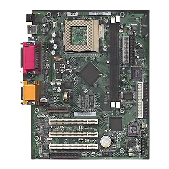
2. FEATURES Photo Of The Motherboard... -
Page 9: Features Of The Motherboard
2. FEATURES Features Of The Motherboard This product is based on the “Micro ATX” form factor. It features the advanced Multimedia function and provides support for business PC maker. This motherboard incorporates Intel 810- DC100 chipset. Providing features such as integrated 2D/3D AGP VGA controller, Ultra DMA 33/66 IDE Interface, ACPI power management, and PCI 3D sound support. - Page 10 2. FEATURES 1MIDI/Game port 2 Standard USB Connector (48MHz). System BIOS 4M-bit Flash device in Firmware Hub(FWH). A unique Roandom Number Generatior in FWH to enable enhanced platform security. PC97 and PnP compatible. ACPI, APM and DMI support. Bootable from CD-ROM supported. Green Features Power Management: APM 1.2.
-
Page 11: Installation
3.INSTALLATION Motherboard Layout & Main Parts CD-in AUX Telephony Game Printer TV/DFP PCI AMR Mic-in Line-in Line-out VGA COM1 USB Mouse/Keyboard COM2 Socket FRONT USB USB Select DIMM1 PC/PCI Audio DIMM2 RING-In Front Panel Speaker JP7/JP9 FAN1 PRI-IDE SEC-IDE Floppy ATX Power JP10/J29... -
Page 12: Significant Parts List
3.INSTALLATION Significant Parts List Front Panel Connectors IrDA Sec. 3.5.6 Reset Switch Sec. 3.5.6 HDD LED Sec. 3.5.6 Sleep Switch Sec. 3.5.6 Power Switch Sec. 3.5.6 Power LED Sec. 3.5.6 Back Panel Connectors PS/2-style keyboard and mouse connectors Sec. 3.5.7 USB connectors Sec. - Page 13 3.INSTALLATION SB-LINK Sec. 3.5.8 UNLock Sec. 3.5.8 CLR PWD/CMOS Sec. 3.5.8 SAFE Mode Sec. 3.5.8...
-
Page 14: Precaution Before Start
3.INSTALLATION Precaution Before Start Static Electricity Damage: Static electricity can easily damage your motherboard. Observing a few basic precautions can help safeguard against damage that could result in expensive repairs. Follow the simple measures below to protect your equipment from static electricity damage: Keep the motherboard and other system components in their anti-static packaging until you are ready to install them. -
Page 15: Slots And Connectors
3.INSTALLATION Slots And Connectors List in sec.3.2.2. PIN 1 PIN 1 In following pages, the triangle s mark stands for pin 1 of connectors. Slots/Connectors List Keyboard/Mouse COM1 USB0/USB1 Game / MIDI Port Line-in, Line-out and Mic-in Printer Port COM 2 Header CD-In J10: AUX-In J11: Telephony... -
Page 16: Cpu (Central Processing Unit)
3.INSTALLATION CPU (Central Processing Unit) This motherboard support a PGA 370 Intel Celeron PGA family processor. To complete CPU installation, please install CPU to socket firmly and arrange jumper settings carefully, presented in sec. 3.2.1 and 3.2.2. PGA370 3.2.1 Install CPU Please follow the below steps to install your CPU, and configure the types and speed in accordingly to the Processor Jumper Setting List. - Page 17 3.INSTALLATION Step 3: Press the handling bar downward to fasten the CPU to the socket. Step 3: Fasten the CPU to socket. Warning : It is strongly recommended that a heatsink and CPU cooling fan be used to prevent the CPU from overheating. Applying a thermal of jelly between the CPU and the heatsink/fan will further cool the CPU.
-
Page 18: System Memory (Dram)
3.INSTALLATION System Memory (DRAM) 3.3.1 DIMM (Dual Inline Memory Module) The IN810 features two168-pin DIMM sockets. You can configure the system memory size from 8MB to 256MB in a variety of ways by using different combinations of the two 168-pin DIMM. Note that you must use only PC/100 compliant DIMMs. DIMM1 DIMM2 3.3.2... -
Page 19: Dimm Module Combinations
3.INSTALLATION 3.3.3 DIMM Module Combinations Each DIMM socket can be inserted with 8MB, 16MB, 32MB, 64MB, 128MB, 256MB DIMM or empty. You can refer to following figure to select one way to insert your DIMM, for example: Select 128MB 256MB Empty 16MB 32MB... -
Page 20: Expansion Slots
3.INSTALLATION Expansion Slots This motherboard contains 4 expansion slots onboard. Three 32-bit PCI expansion slots and one AMR slot as shown above. All three PCI expansion slots accept PCI us master cards and are fully supported by the PCI 2.2 specification. The Audio Modem Riser (AMR) connector which supports an industry-standard riser board and interface for both audio and modem, while also addressing specific function limitations of previous audio and modem subsystem. -
Page 21: Connectors
3.INSTALLATION Connectors This IN810 motherboard contains IDE, floppy, power input, front panel, back panel and additional connectors. Pri. IDE Sec IDE 3.5.1 Primary IDE Connector (J31, 39-pin block) This connector supports two primary channel IDE devices via a ribbon cable. When two IDE devices are installed using the primary IDE connector, make sure that the second IDE device is set to slave mode as indicated in the device’s manual. -
Page 22: Floppy Drive Connector (J23, 33-Pin Block)
3.INSTALLATION 3.5.3 Floppy Drive Connector (J23, 33-pin block) The FDC sub-system can control three types of floppy drives (1.2, 1.44 and 2.88MB) or compatible tape drives. The connection to the floppy drive is via a header. The floppy disk interface includes 48mA drivers and inputs on the drive interface. -
Page 23: Front Panel Connectors (J28 20-Pin Header)
3.INSTALLATION 3.5.6 Front Panel connectors (J28 20-pin header) Front Panel includes headers for the following six I/O connectors: Power Switch, Power LED, Speaker, Reset, Sleep and HDD LED. GRN/YEL PWR Sleep IrDA Speaker HD LED Reset Infrared (IrDA) connector (4-pin) The IN810 offers an IrDA infrared header that supports third party infrared modules. - Page 24 3.INSTALLATION (standby) mode in one of the following ways: ♦ Optional front panel sleep/resume button ♦ Prolonged system inactivity using the BIOS inactivity timer feature (Section 4.5) The 2-pin header supports a front panel sleep/resume switch, which must be a momentary SPST type that is normally open Power Switch (2-pin) This connector supports the ATX case-mounted Power Switch, which in turn supports...
-
Page 25: Back Panel Connectors
3.INSTALLATION 3.5.7 Back Panel Connectors Printer Game / MIDI PS/2 USB COM1 Audio headers PS/2 Keyboard and Mouse Ports (J2) The motherboard offers 1 PS/2 Keyboard and 1 PS/2 Mouse port. Mouse Keyboard Universal Serial Bus (USB) Ports (J4) The motherboard has two USB connectors. USB devices provide a more convenient operating environment and improve data transferring capacity. - Page 26 3.INSTALLATION Parallel Port (Printer, J7) The IN810 includes a parallel port (EPP/ECP compatible). The parallel port is capable of being disabled or remapped to either the secondary LPT address or the primary LPT address through BIOS if another parallel port is installed. Printer(Parallel ) Serial Port/VGA Port (COM1, J3/ VGA, J1) The motherboard has two serial ports (one on rare panel, one on board).
- Page 27 3.INSTALLATION GAME / MIDI Port (J5) TheIN810 integrate a Game/MIDI port. This port can let you pulg a joystick or MIDI device. GAME/MIDI Audio Port ( Line-in, Line-out, MIC-in) (J6) The IN810 also provides external sound system through a user accessible stereo jack connector soldered to the PWA.This jack allow the connection of self-amplified speakers, Line-in voice input and MIC-in voice input.
-
Page 28: Additional Connectors
3.INSTALLATION 3.5.8 Additional Connectors Ring-In Front USB Header JP10 On board Codec Ring In (J27, 2-pin) This header is used for remote wakeup of the computer through a modem. Ring-In requires an add-in modem card with remote wakeup capabilities. The remote wakeup header on the add-in modem card must be connected to the onboard Ring-In header. - Page 29 3.INSTALLATION USB Select Jumper USB Select Front USB Back USB ON Unlock (JP7, 2-pin) This Jumper for Flash BIOS. When you need flash BIOS will installed this Jumper. CLR Power/CMOS (JP9, 3-pin) This Jumper Choose for clear CMOS Setting you can clear password or all CMOS Setting to Default.
- Page 30 3.INSTALLATION PC/PCI Audio CD-IN AUX-IN CPU FAN Telephony WOL (Wake On LAN ) (J19, 3-pin) This header is used for remote wakeup of the computer through a network. WOL requires a PCI add-in network interface card (NIC) with remote wakeup capabilities. The remote wakeup header on the NIC must be connected to the onboard Wake on LAN header.
- Page 31 3.INSTALLATION and audio-out signal interface is necessary for telephony applications such as speakerphones, fax modems, and answering machines.. CD-IN Header (J9, 4-pin, Black) A connector is available for audio input from CD-ROM drives. PC/PCI Audio Header (J21, 6-pin) A connector provides Sound Blaster compatibility for some legacy PCI Audio Card. AUX-IN Header (J10, 4-pin, White) Access to the AUX-IN connector for audio input from AUX devices.
-
Page 32: Ready To Turn On Power
3.INSTALLATION Ready To Turn On Power ♦ Check Again Is the CPU installed exactly and firmly into socket (Sec. 3.2)? Are all the DRAM modules installed properly (Sec. 3.3)? Did you insert expansion card (VGA, Sound…. etc.) already (Sec. 3.4)? Are you sure that all the connectors (described in Sec 3.5) have been connected to their variable devices (Sec. - Page 33 3.INSTALLATION SETUP.
- Page 34 3.INSTALLATION...
-
Page 35: Bios Setup
4. BIOS SETUP 4. BIOS SETUP The IN810 motherboard uses AMI BIOS, which is stored in a Flash EEPROM and can be upgraded by a floppy disk-based program. The BIOS has a built-in Setup Program that allows users to modify the basic system configuration settings. -
Page 36: Setup Keys
4. BIOS SETUP 4. BIOS SETUP 4.1.1 Setup Keys These keys help you navigate in Setup: <↑> , <↓> Move to previous / next item Change Values <←> , <→> Move to the item in the left or right hand Main Menu –... -
Page 37: Main Setup Menu
4. BIOS SETUP 4. BIOS SETUP Main Setup Menu When you enter the AMI BIOS CMOS Setup Utility, a Main Menu (Figure 1) appears on the screen. The Main Menu allows you to select from several Setup functions and two exit choices. Use the arrow keys to select among the items and press Enter to accept and enter the sub-menu. - Page 38 4. BIOS SETUP 4. BIOS SETUP Following is a brief summary of each Setup category. Standard CMOS Options in the original PC AT-compatible BIOS. Advanced CMOS AMI enhanced BIOS options. Setup Advanced Chipset Options specific to your system chipset. Setup Power Management Advanced Power Management (APM) options.
-
Page 39: Standard Cmos Setup Menu
4. BIOS SETUP 4. BIOS SETUP Standard CMOS Setup Menu In the Standard CMOS Menu (Figure2) you can set the system clock and calendar, record disk drive parameters and the video subsystem type, and select the type of errors that stop the BIOS POST. AMIBIOS SETUP –... - Page 40 4. BIOS SETUP 4. BIOS SETUP The BIOS can automatically detect the specifications and optimal operating mode of almost all IDE hard drives. When you select type AUTO for a hard drive, the BIOS detects its specifications during POST, every time the system boots. If you do not want to select drive type AUTO, other methods of selecting the drive type are available: Match the specifications of your installed IDE hard drive(s) with the...
- Page 41 4. BIOS SETUP 4. BIOS SETUP Drive A/B type Select the correct specifications for the diskette drive(s) installed in the computer. Not Installed No diskette drive installed 360K, 5.25 in 5-1/4 inch PC-type standard drive; 360 kilobyte capacity 1.2M, 5.25 in 5-1/4 inch AT-type high-density drive;...
- Page 42 4. BIOS SETUP 4. BIOS SETUP factor, landing zone, and number of sectors, Drives whose specifications do not accommodate any pre-defined type are classified as type USER. • Size: Disk drive capacity (approximate). Note that this size is usually slightly greater than the size of a formatted disk given by a disk-checking program.
-
Page 43: Extended Memory
4. BIOS SETUP 4. BIOS SETUP conventional applications use this area. Extended Memory Above the 126-MB boundary. Early IBM personal computers could not use memory above 126 MB, but current PCs and their software can use extended memory. Advanced CMOS Setup Menu This screen (Figure 3) contains industry-standard options additional to the core PC AT BIOS. - Page 44 4. BIOS SETUP 4. BIOS SETUP This option sets the type of device for the second boot drives that the AMIBIOS attempts to boot from after AMIBIOS POST completes. 3rd Boot Device This option sets the type of device for the third boot drives that the AMIBIOS attempts to boot from after AMIBIOS POST completes.
- Page 45 4. BIOS SETUP 4. BIOS SETUP system memory on the motherboard. CPU MicroCode Updation Set this option to Enabled to permit the CPU to be updated online at any time. System BIOS Cacheable When set to Enabled, the contents of the F0000h system memory segment can be read from or written to cache memory.
-
Page 46: Advanced Chipset Setup Menu
4. BIOS SETUP 4. BIOS SETUP Advanced Chipset Setup Menu AMIBIOS SETUP – ADVANCED CHIPSET SETUP (C) 1998 American Megatrends, Inc. ALL Rights Reserved Enabled USB Function Available Options: USB KB/Mouse Legacy Support Disabled Disabled Onboard AC’97 Audio OnChip Audio Enabled Memory Hold Move to items... - Page 47 4. BIOS SETUP 4. BIOS SETUP Onboard AC’97 Audio Allows the motherboard’s BIOS to detect whether you are using any audio device. If a audio device is detected, the onboard audio controller will be enabled; if no audio device is detevted, the onboard audio controller will be disabled. If you want to use different controller cards to connect audio connectors, set these fields to Disabled.
-
Page 48: Power Management Setup Menu
4. BIOS SETUP 4. BIOS SETUP Power Management Setup Menu AMIBIOS SETUP – POWER MANAGEMENT SETUP (C) 1998 American Megatrends, Inc. ALL Rights Reserved Power Management/APM Enabled Available Options: Standby Time Out Disabled Suspend Time Out Disabled Move to items Enter Sub-Menu Power Button Mode On/Off... - Page 49 4. BIOS SETUP 4. BIOS SETUP Suspend Pushing the Power button places the computer in Suspend mode or Full On power mode. Green PC Monitor Power State This option specifies the power state that the green PC-compliant video monitor enters when AMIBIOS places it in a power saving state after the specified period of display inactivity has expired.
-
Page 50: Pci/Plug And Play Setup Menu
4. BIOS SETUP 4. BIOS SETUP PCI/Plug and Play Setup Menu AMIBIOS SETUP – PCI/PLUG AND PLAY SETUP (C) 1998 American Megatrends, Inc. ALL Rights Reserved Plug and Play Aware O/S Available Options: Primary Graphics Adapter OnBoard PCI VGA Palette Snoop Disabled Allocate IRQ to PCI VGA Move to items... - Page 51 4. BIOS SETUP 4. BIOS SETUP VGA Palette Action Snoop Bit Disabled Data read and written by the CPU is only directed to the PCI VGA device's palette registers. Enabled Data read and written by the CPU is directed to the both the PCI VGA device's palette registers and the ISA VGA device palette registers, permitting the palette registers of both devices to be identical.
-
Page 52: Peripherals Setup Menu
4. BIOS SETUP 4. BIOS SETUP Peripherals Setup Menu AMIBIOS SETUP – PERIPHERAL SETUP (C) 1998 American Megatrends, Inc. ALL Rights Reserved 66.8MHz CPU Frequency Available Options: 3.0x CPU Ratio Select 125MHz -= System Hardware Monitor = - 127MHz Always Off AC Power Loss Control Move to items 130MHz... - Page 53 4. BIOS SETUP 4. BIOS SETUP System Hardware Monitor AC Power Loss Control The setting are power ON/OFF or Last status. During power ON, after every AC/Power Loss, the system will be turned on. During last status, after every AC/Power Loss, whatever the system status, it will be the same when AC power returns.
- Page 54 4. BIOS SETUP 4. BIOS SETUP Parallel Port Mode This option specifies the parallel port mode. The Optimal default setting is Normal. The Fail-Safe default setting is Disabled. The settings are: Setting Description The normal parallel port mode is used. Normal The parallel port can be used with devices that adhere to the Enhanced Parallel Port (EPP) specification.
- Page 55 4. BIOS SETUP 4. BIOS SETUP Set this field to Enabled if you wishto use your PS2 keyboard(by pressing the spacebar)or PS2 mouse(by clicking on the left button) to power up your computer. This feature require an ATX power supply that can supply at least 300mA on the +5VSB lead.
-
Page 56: Auto-Detection Ide Hdd
4. BIOS SETUP 4. BIOS SETUP Auto-Detection IDE HDD BIOS setup will display all possible modes that supported by the HDD including NORMAL, LBA & LARGE. If HDD does not support LBA modes, no ‘LBA’ option will be shown. If no of cylinders is less than or equal to 1024, no ‘LARGE’ option will be show. -
Page 57: Auto Configuration With Optimal Settings
4. BIOS SETUP 4. BIOS SETUP 4.12 Auto Configuration with Optimal Settings The chipset defaults are settings which provide for maximum system performance. While AMI has designed the custom BIOS to maximize performance, the manufacturer has the right to change these defaults to meet their needs. 4.13 Auto Configuration with Fail Safe Settings AMIBIOS will automatically set all AMIBIOS Setup options to a complete set of...
Need help?
Do you have a question about the IN810EP and is the answer not in the manual?
Questions and answers