Table of Contents
Advertisement
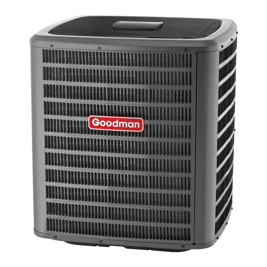
CONDENSING UNIT
AIR CONDITIONING
INSTALLATION & SERVICE REFERENCE
Important Safety Instructions
The following symbols and labels are used throughout this
manual to indicate immediate or potential safety hazards. It is
the owner's and installer's responsibility to read and comply
with all safety information and instructions accompanying these
symbols. Failure to heed safety information increases the risk
of personal injury, property damage, and/or product damage.
WARNING
HIGH VOLTAGE!
Disconnect ALL power before servicing.
Multiple power sources may be present.
Failure to do so may cause property damage,
personal injury or death.
WARNING
ONLY individuals meeting the requirements of an
"Entry Level Technician" as specified by the Air
Conditioning and Refrigeration Institute (ARI) may use
this information. Attempting to install or repair this
unit without such background may result in product
damage, personal injury, or death.
Shipping Inspection
Always keep the unit upright; laying the unit on its side or top
may cause equipment damage. Shipping damage, and subse-
quent investigation is the responsibility of the carrier. Verify
the model number, specifications, electrical characteristics,
and accessories are correct prior to installation. The distribu-
tor or manufacturer will not accept claims from dealers for trans-
portation damage or installation of incorrectly shipped units.
Codes & Regulations
This product is designed and manufactured to comply with
national codes. Installation in accordance with such codes and/
or prevailing local codes/regulations is the responsibility of the
installer. The manufacturer assumes no responsibility for equip-
ment installed in violation of any codes or regulations.
The United States Environmental Protection Agency (EPA)
has issued various regulations regarding the introduc-
tion and disposal of refrigerants. Failure to follow these
regulations may harm the environment and can lead to
the imposition of substantial fines. Should you have any
questions please contact the local office of the EPA.
If replacing a condensing unit or air handler, the system must
be manufacturer approved and Air Conditioning and Refrigera-
tion Institute (ARI) matched. NOTE: Installation of unmatched
systems is strongly discouraged.
Operating the unit in a structure that is not complete (either as
Goodman Manufacturing Company, L.P. © 2005-2006
2550 North Loop West, Suite 400, Houston, TX 77092
www.goodmanmfg.com -or- www.amana-hac.com
P/N: IO-258D
Date: October 2006
part of new construction or renovation) will void the warranty.
Installation Clearances
Special consideration must be given to location of the con-
densing unit(s) in regard to structures, obstructions, other units,
and any/all other factors that may interfere with air circulation.
Where possible, the top of the unit should be completely unob-
structed; however, if vertical conditions require placement be-
neath an obstruction there should be a minimum of 60
inches between the top of the unit and the obstruction(s).
The specified dimensions meet requirements for air circulation
only. Consult all appropriate regulatory codes prior to deter-
mining final clearances.
Another important consideration in selecting a location for the
unit(s) is the angle to obstructions. Either side adjacent the
valves can be placed toward the structure provided the side
away from the structure maintains minimum service clearance.
Corner installations are strongly discouraged.
NOT
RECOMMENDED
B
A
AA
C
AA
AA
A
C
Minimum Airflow Clearance
Model Type
Residential
Light Commercial
This unit can be located at ground floor level or on flat roofs. At
ground floor level, the unit must be on a solid, level foundation
that will not shift or settle. To reduce the possibility of sound
transmission, the foundation slab should not be in contact with
or be an integral part of the building foundation. Ensure the
foundation is sufficient to support the unit. A concrete slab
raised above ground level provides a suitable base.
B
B
B
AA
C
AA
AA
AA
C
A
B
C
10"
10"
18"
12"
12"
18"
OK!
OK!
OK!
OK!
OK!
OK!
AA
20"
24"
Advertisement
Chapters
Table of Contents

Related Manuals for Goodman ASX


Summary of Contents for Goodman ASX
- Page 1 CONDENSING UNIT Goodman Manufacturing Company, L.P. © 2005-2006 2550 North Loop West, Suite 400, Houston, TX 77092 AIR CONDITIONING www.goodmanmfg.com -or- www.amana-hac.com INSTALLATION & SERVICE REFERENCE P/N: IO-258D Date: October 2006 Important Safety Instructions part of new construction or renovation) will void the warranty.
- Page 2 Refrigerant Lines Rooftop Installations If it is necessary to install this unit on a roof structure, ensure CAUTION the roof structure can support the weight and that proper con- The compressor POE oil for R-410A units is extremely sideration is given to the weather-tight integrity of the roof. Since susceptible to moisture absorption and could cause the unit can vibrate during operation, sound vibration transmis- compressor failure.
- Page 3 side the refrigerant lines. The POE oils used in R-410A Liquid Line applications will clean any copper-oxide present from the Suction Line inside of the refrigerant lines and spread it throughout the system. This may cause a blockage or failure of the me- tering device.
- Page 4 2. Evacuate the system to 250 microns or less using suc- tion. Wires should be sized to limit voltage drop to 2% (max.) tion and liquid service valves. Using both valves is nec- from the main breaker or fuse panel to the condensing unit. essary as some compressors create a mechanical seal Consult the NEC, CEC, and all local codes to determine the separating the sides of the system.
- Page 5 CAUTION Thermostat Use refrigerant certified to ARI standards. Used refrigerant Single-Stage Heating with Single-Stage Cooling may cause compressor damage, and will void the warranty. Most portable machines cannot clean used refrigerant to meet ARI standards. NOTICE FURNACE OR Violation of EPA regulations may result in fines or other DEHUM TWIN AIR HANDLER...
- Page 6 SATURATED SUCTION PRESSURE SATURATED LIQUID PRESSURE TEMPERATURE CHART TEMPERATURE CHART SATURATED SUCTION SATURATED LIQUID SUCTION PRESSURE LIQUID PRESSURE TEMPERATURE ºF TEMPERATURE ºF PSIG R-22 R-410A PSIG R-22 R-410A Expansion Valve System Single Speed Application Two Speed Application Run the remote on low stage cooling for 10 minutes until refrig- 1.
- Page 7 Troubleshooting Information System Unsatisfactory Complaint No Cooling Operating Cooling Pressures POSSIBLE CAUSE Test Method DOTS IN ANALYSIS Remedy GUIDE INDICATE "POSSIBLE CAUSE" • Power Failure Test Voltage • • • Blown Fuse Impact Fuse Size & Type • • • •...
- Page 8 Blowers, Coils, & Accessories This manual is to be used by qualified, professionally trained HVAC technicians only. Goodman does not assume any responsibility for property damage or personal injury due to improper service procedures or services performed by an unqualified person.
-
Page 9: Table Of Contents
ANY JU RISDICTIONS REQU IRE A LICENSE TO INSTALL OR SERVICE HEATING AN D AIR CONDITIONING EQUIPMENT. To locate an authorized servicer, please consult your telephone book or the dealer from whom you purchased this product. For further assistance, please contact: CONSUMER INFORMATION LINE GOODMAN ® BRAND PRODUCTS AMANA ®... -
Page 10: Important Information
IMPORTANT INFORMATION SAFE REFRIGERANT HANDLING While these items will not cover every conceivable situation, they should serve as a useful guide. WARNING WARNING EFRIGERANTS ARE HEAVIER THAN AIR. HEY CAN "PUSH OUT" THE O AVOID POSSIBLE EXPLOSION: OXYGEN IN YOUR LUNGS OR IN ANY ENCLOSED SPACE. O AVOID •... -
Page 11: Product Identification
PRODUCT IDENTIFICATION Minor Revision Brand Name A: Initial Release S: Goodman (High Feature Set Models) A: Amana Deluxe Major Revision A: Initial Release Product Family S: Split System Electrical 1: 208/230V/60Hz/1ph Product Type 3: 208/230V/60Hz/3ph 4: 460V/60Hz/3ph X: Condenser R-410A... - Page 12 PRODUCT IDENTIFICATION Design Series Voltage/Hz/Phase MB: Modular Blower 1: 208-230/60/1 Motor Types Design Series E: Variable-speed A: First Series R: Constant-speed Circuit Breaker Air Flow Delivered 08: 800 CFM 2: 208/230-60-1 12: 1,200 CFM 16: 1,600 CFM Factory-installed 20: 2,000 CFM Electric Heat 00: No Heat MODEL...
- Page 13 PRODUCT IDENTIFICATION 1824 Product Type Revision C: Indoor Coil A: Revision Applicaton Refrigerant A: Upflow/Downflow Coil H: Horizontal A Coil 6: R-22 or R-41A S: Horizontal Slab Coil 4: R-410A Cabinet Finish Nominal Width for Gas Furnace U: Unpainted P: Painted A: Fits 14"...
- Page 14 PRODUCT IDENTIFICATION THIS NOMENCLATURE IS TO BE USED AFTER JULY 2006 3642 Product Type Minor Revision A: Single Piece Air Handler Application C: Ceiling Mount PSC Motor Refrigerant D: Downflow PSC Motor E: Multi-Position Variable Speed Motor R: Multi-Position PSC Motor W:Wall Mount PSC Motor Cabinet Finish Electrical Supply...
- Page 15 {A} Amana® Brand Deluxel {S} Split System {X} Condenser R-410A {**} SEER {****} Nominal Capacity {1} Voltage {*} Revision {S} Goodman - High feature set model {S} Split System {X} Heat Pump R-410A {**} SEER {****} Nominal Capacity {1} Voltage {*} Revision SSZ14****1* {A} Amana®...
-
Page 16: Accessories
ACCESSORIES SSX14 SSX14 SSX14 SSX14 SSX14 SSX14 SSX14 SSX14 Model Description ASC01 Anti-Short Cycle Kit CSR-U-1 Hard-start Kit CSR-U-2 Hard-start Kit CSR-U-3 Hard-start Kit Freeze Protection Kit FSK01A TX2N4³ TXV Kit TXV Kit TX3N4 TXV Kit TX5N4 Installed on indoor coil Required for heat pump applications where ambient temperatures fall below 0°F with 50% or higher relative humidy. - Page 17 ACCESSORIES SSX16 SSX16 SSX16 SSX16 SSX16 SSX16 SSX16 Model Description ASC01 Anti-Short Cycle Kit CSR-U-1 Hard-start Kit CSR-U-2 Hard-start Kit CSR-U-3 Hard-start Kit FSK01A Freeze Protection Kit TX2N4³ TXV Kit TX3N4³ TXV Kit TX5N4³ TXV Kit Installed on indoor coil Required for heat pump applications where ambient temperatures fall below 0°F with 50% or higher relative humidy.
- Page 18 ACCESSORIES SSZ14 SSZ14 SSZ14 SSZ14 SSZ14 SSZ14 SSZ14 SSZ14 Model Description AFE18-60A All-Fuel Kit ASC01 Anti-Short Cycle Kit CSR-U-1 Hard-start Kit CSR-U-2 Hard-start Kit CSR-U-3 Hard-start Kit Freeze Protection Kit FSK01A OT/EHR18-60 Emergency Heat Relay kit OT18-60A² Outdoor Thermostat w/ Lockout Stat TX2N4³...
- Page 19 ACCESSORIES SSZ16 SSZ16 SSZ16 SSZ16 SSZ16 SSZ16 SSZ16 Model Description AFE18-60A All-Fuel Kit ASC01 Anti-Short Cycle Kit CSR-U-1 Hard-start Kit CSR-U-2 Hard-start Kit CSR-U-3 Hard-start Kit Freeze Protection Kit FSK01A OT/EHR18-60 Emergency Heat Relay Kit OY/EH R18-60 Emergency Heat Relay Kit OT18-60A²...
- Page 20 ACCESSORIES EXPANSION VALVE KITS For Applications requiring 1/4 FLARE CONNECTION a field installed access fitting BULB TO BE LOCATED AT 10 OR 2 O'CLOCK BULB SUCTION LINE EVAPORATOR COIL TAILPIECE PISTON SEAL SUPPLIED W/ KIT SEAL SUPPLIED W/ KIT SEAL DISTRIBUTOR EXPANSION VALVE BODY...
- Page 21 ACCESSORIES FSK01A FREEZE THERMOSTAT Wire Nut Wire Nut Install Line Install Line Thermostat Thermostat Here Here Wire Nut Wire Nut ASC01A ANTI-SHORT -CYCLE CONTROL KIT SHORT CYCLE PROTECTOR YELLOW 1 CONTACTOR T2 T1 BLACK 1 THERMOSTAT L2 L1 WIRE UNIT TERMINAL BLACK 1 BOARD...
- Page 22 ACCESSORIES COIL ACCESSORIES COIL MODEL TX2N4 TXV KIT TX3N4 TXV KIT TX5N4 TXV KIT FSK01A FREEZE PROTECTION KIT CA*F030B4* CA*F036B4* CA*F042C4* CA*F048C4* CA*F057D4* CA*F060D4* CHPF030A4* CHPF036B4* CHPF042A4* CHPF048D4* CHPF060D4* CH36FCB CH48FCB CH60FCB CA*F18246* CA*F30306* CA*F36426* CHPF18246* CHPF30306* CHPF36426* CSCF1824N6* CSCF303N6* CSCF3642N6* HKR SERIES ELECTRIC HEAT KITS ELECTRIC HEAT KIT APPLICATIONS - MBR &...
- Page 23 ACCESSORIES ELECTRIC HEAT KIT APPLICATIONS - ARUF ARUF1729 ARUF1824 ARUF1931 ARUF3030 ARUF3642 ARUF3743 ARUF4860 1/16 1/16 1/16 1/16 1/16 1/16 1/16 HKR-03* HKR-05*, HKR-05C* HKR-06* HKR-08*, HKR-08C* HKR-10*, HKR-10C* HKR-15C* HKR-20C* HKR-21C* ^ HKR3-15* ^ HKR3-20* * Revision level that may or may not be designated C Circuit breaker option ^ Heat kit requires three-phase power supply Air handler must either be on medium or high speed...
-
Page 24: Product Design
All units are constructed with R-4.2 insulation. In areas of extreme humidity (greater than 80% ASX, SSX, ASZ and SSZ models are available in 1 1/2 through consistently), insulate the exterior of the blower with insula- 5 ton sizes and use R-410A refrigerant. They are designed for tion having a vapor barrier equivalent to ductwork insulation, 208/230 volt single phase applications. - Page 25 PRODUCT DESIGN The ASX [16 & 18] and ASZ [16 & 18] series split system units use a two-stage scroll compressor. The two-step modulator has an internal unloading mechanism that opens a bypass port in the first compression pocket, effectively reducing the displacement of the scroll.
-
Page 26: System Operation
SYSTEM OPERATION COOLING HEATING The refrigerant used in the system is R-410A. It is a clear, The heating portion of the refrigeration cycle is similar to the colorless, non-toxic and non-irritating liquid. R-410A is a cooling cycle. By energizing the reversing valve solenoid coil, 50:50 blend of R-32 and R-125. - Page 27 SYSTEM OPERATION DEFROST CYCLE HEATING CYCLE The defrosting of the outdoor coil is jointly controlled by the The ASZ and SSZ model heat pumps use a different control defrost control board and the defrost thermostat. circuit than preceding heat pump models. These models do not use a reversing relay to energize the reversing valve.
- Page 28 SYSTEM OPERATION COOLING CYCLE Reversing Valve (Energized) Indoor Outdoor Coil Coil Accumulator Thermostatic Expansion Valve Bi-Flow Filter Dryer Check Valve HEATING CYCLE Reversing Valve (De-Energized) Indoor Outdoor Coil Coil Accumulator Thermostatic Expansion Valve Bi-Flow Filter Dryer Check Valve...
- Page 29 SYSTEM OPERATION EXPANSION VALVE/CHECK VALVE ASSEMBLY EXPANSION VALVE/CHECK VALVE ASSEMBLY IN COOLING OPERATION IN HEATING OPERATION ® Most expansion valves used in current Amana Brand Heat Pump products use an internally checked expansion valve. This type of expansion valve does not require an external check valve as shown above. However, the principle of operation is the same.
- Page 30 SYSTEM OPERATION AFE18-60A CONTROL BOARD controls, if the outdoor thermostat fails closed in this position during the heating season, it will turn on the furnace during DESCRIPTION the cooling season on a “Y” cooling demand. In this The AFE18 control is designed for use in heat pump applica- situation, the furnace produces heat and increases the tions where the indoor coil is located above/downstream of a indoor temperature thereby never satisfying the cooling...
-
Page 31: Troubleshooting Chart
TROUBLESHOOTING CHART COOLING/H P ANALYSIS CHART Sys te m Uns atis factor y Com plaint No Cooling Ope r ating Cooling/He ating Pr e s s ur e s P OS SIBLE CAUSE Te st Me thod DOTS IN ANALYSIS Re m e dy GUIDE INDICATE "P OS SIBLE CAUSE"... -
Page 32: Service Table Of Contents
Checking Thermostat, Wiring & Anticipator .. 26 S-40 MBR/ARUF Electronic Blower Time Delay ..41 S-3A Thermostat & Wiring ........26 S-41 MBE/AEPF With SSX and ASX units ... 43 S-3B Cooling Anticipator ........27 S-3C Heating Anticipator ........27 S-60 Electric Heater (optional item) ....... -
Page 33: Servicing
SERVICING S-2 CHECKING WIRING S-1 CHECKING VOLTAGE 1. Remove outer case, control panel cover, etc., from unit being tested. With power ON: HIGH VOLTAGE! Disconnect ALL power before servicing or installing. Multiple power sources WARNING may be present. Failure to do so may Line Voltage now present. -
Page 34: S-3B Cooling Anticipator
SERVICING element helping the thermostat call for the next cooling cycle. 4. Check the continuity of the thermostat and wiring. Repair This prevents the room temperature from rising too high or replace as necessary. before the system is restarted. A properly sized anticipator Resistance Heaters should maintain room temperature within 1 1/2 to 2 degree 1. -
Page 35: Checking Transformer & Control Circuit
SERVICING With power ON: S-4 CHECKING TRANSFORMER AND CONTROL CIRCUIT WARNING Line Voltage now present. HIGH VOLTAGE! 1. Apply 24 VAC to terminals R and R Disconnect ALL power before servicing 2. Should read 24 VAC at terminals Y and Y or installing. -
Page 36: Checking Contactor And/Or Relays
SERVICING S-7 CHECKING CONTACTOR AND/OR RELAYS HIGH VOLTAGE! Disconnect ALL power before servicing or installing. Multiple power sources VOLT/OHM may be present. Failure to do so may METER cause property damage, personal injury or death. Ohmmeter for testing holding coil The compressor contactor and other relay holding coils are Voltmeter for testing contacts wired into the low or line voltage circuits. -
Page 37: Checking High Pressure Control
SERVICING WARNING Line Voltage now present. OHMMETER TESTING FAN RELAY 4. Using an ohmmeter, test between 2 and 4 - should read continuous . Test between 5 and 6 - should read open. If it cuts-out at 610 PSIG ± 10 PSIG, it is operating normally 5. -
Page 38: S-15A Resistance Check
SERVICING SCROLL COMPRESSOR MODELS S-15A RESISTANCE CHECK In most cases hard start components are not required on Scroll compressor equipped units due to a non-replaceable WARNING check valve located in the discharge line of the compressor. HIGH VOLTAGE! However, in installations that encounter low lock rotor volt- Disconnect ALL power before servicing or installing. -
Page 39: S-15B Capacitance Check
SERVICING 1. Remove the motor leads from its respective connection S-15B CAPACITANCE CHECK points and capacitor (if applicable). Using a hookup as shown below, take the amperage and 2. Check the continuity between each of the motor leads. voltage readings and use them in the formula: 3. - Page 40 SERVICING Lines 1 and 2 will be connected for 12OVAC Power Connector applications only AC Line Connection AC Line Connection OUT - OUT + ADJUST +/- G (FAN) Y/Y2 COOL EM Ht/W2 24 Vac (R) DELAY HEAT COMMON2 BK/PWM (SPEED) W/W1 COMMON1 O (REV VALVE)
- Page 41 SERVICING...
- Page 42 SERVICING...
-
Page 43: S-16D Ecm Cfm Adjustments
SERVICING S-16C CHECKING ECM MOTOR WINDINGS MOTOR SPEED ADJUSTMENT Each ECM™ blower motor has been preprogrammed for operation at 4 distinct airflow levels when operating in Cool- ing/Heat Pump mode or Electric Heat mode. These 4 distinct levels may also be adjusted slightly lower or higher if desired. HIGH VOLTAGE! The adjustment between levels and the trim adjustments are Disconnect ALL power before servicing... -
Page 44: S-16E Blower Performance Data
SERVICING THERMOSTAT “FAN ONLY” MODE AEPF DIPSWITCH FUNCTIONS During Fan Only Operations, the CFM output is 30% of the cooling setting. EMERGENCY HEAT PUMP CFM Model Switch 1 Switch 2 BACKUP CFM WITH BACKUP 1100 CFM TRIM ADJUST 1210 AEPF1830 Minor adjustments can be made through the dip switch combination of 7-8. -
Page 45: Checking Compressor Windings
SERVICING S-17 CHECKING COMPRESSOR HIGH VOLTAGE! WARNING Disconnect ALL power before servicing or installing. Multiple power sources Hermetic compressor electrical terminal venting can may be present. Failure to do so may be dangerous. When insulating material which cause property damage, personal injury supports a hermetic compressor or electrical terminal or death. -
Page 46: S-17C Unloader Test
SERVICING 2. Identify the leads and using a Megger, Hi-Potential Unloader Test Procedure Ground Tester, or other suitable instrument which puts If it is suspected that the unloader is not working, the out a voltage between 300 and 1500 volts, check for a following methods may be used to verify operation. -
Page 47: Testing Crankcase Heater (Optional Item)
SERVICING 2. With the protective terminal cover in place, use the three When stuck in the mid-position, part of the discharge gas leads to the compressor terminals that were discon- from the compressor is directed back to the suction side, nected at the nearest point to the compressor and resulting in excessively high suction pressure. -
Page 48: Checking Heater Limit Control(S)
SERVICING 3. Check the temperature at which the control opens its During a cooling or heat pump heating demand, 24Vac is contacts by raising the temperature of the control. Part # supplied to terminal “G” of the EBTDR to turn on the blower 0130M00009P which is used on 2 and 2.5 ton units motor. - Page 49 SERVICING 2.0 Heating Operation On heat pump units, when the room thermostat set to the heating mode, the reversing valve is not energized. As long 2.1 On a demand for heat, the room thermostat energizes as the thermostat is set for heating, the reversing valve will “W1”...
-
Page 50: Mbe/Aepf With Ssx And Asx Units
CONDENSERS On heat pump units, when the room thermostat is set to the When used with a single stage SSX and ASX condensers, heating mode, the reversing valve is not energized. As long dip switch #4 must be set to the on position on the VSTB as the thermostat is set for heating, the reversing valve will be inside the MBE/AEPF. - Page 51 SERVICING thermostat will remove the 24Vac from “W2” and the VSTB these can change the operation of the electric heaters during the heating mode. This sequence of operation will remove the 24Vac from HR2. The contacts on HR2 will does not cover those applications. open between 30 to 70 seconds and heater elements #3 and #4 will be turned off and the blower motor will change to low 4.1 On a demand for first stage heat with heat pump units,...
- Page 52 1.0 COOLING OPERATION heating mode, the reversing valve is not energized. As long When used with the ASX two stage condensers, dip as the thermostat is set for heating, the reversing valve will be switch #4 must be set to the OFF position on the in the de-energized position for heating except during a VSTB inside the MBE/AEPF.
- Page 53 SERVICING 2.2 HR1 contacts M1 and M2 will close within 10 to 20 3.1 On a demand for cooling, the room thermostat energizes seconds and turn on heater element #1. At the same “G” and “Y1” and 24Vac is supplied to “G” and “Ylow/Y1” time, if the heater assembly contains a second heater of the MBE unit.
-
Page 54: Electric Heater (Optional Item)
SERVICING 4.6 When the first stage heat demand “Y1” is satisfied, the 4.2 If a thermostat that provides a “Y2” demand in heating is room thermostat will remove the 24Vac from “G” and used and first stage heating cannot satisfy the demand, “Ylo/Y1”... -
Page 55: S-61A Checking Heater Limit Control(S)
SERVICING Other components such as a Heating/Cooling Thermostat ELECTRIC HEATER CAPACITY BTUH and Outdoor Thermostats are available to complete the installation. 14.2 19.5 21.0 The system CFM can be determined by measuring the static pressure external to the unit. The installation manual BTUH 10200 16200 20400 23800 32400 48600 66500 71600 supplied with the blower coil, or the blower performance table in the service manual, shows the CFM for the static mea-... -
Page 56: S-61B Checking Heater Fuse Line
SERVICING 2. Using an ohmmeter, test across the fuse link for continu- BRAZING MATERIALS ity - no reading indicates the link is open. Replace as Copper to Copper Joints - Sil-Fos used without flux (alloy necessary. of 15% silver, 80% copper, and 5% phosphorous). Recom- NOTE: The link is designed to open at approximately 333°F. -
Page 57: Evacuation
SERVICING The equipment required to thoroughly evacuate the system 4. Evacuate the system to at least 29 inches gauge before is a high vacuum pump, capable of producing a vacuum opening valve to thermocouple vacuum gauge. equivalent to 25 microns absolute and a thermocouple 5. -
Page 58: Checking Compressor Efficiency
SERVICING If the test shows: NOTE: R410A should be drawn out of the storage container or drum in liquid form due to its fractionation properties, but a. Below normal high side pressure. should be "Flashed" to its gas state before entering the b. -
Page 59: Overfeeding
If a vertical installation cannot be avoided, the bulb must be mounted so that the capillary tubing comes out at the top. THE VALVES PROVIDED BY GOODMAN ARE DESIGNED TO MEET THE SPECIFICATION REQUIREMENTS FOR OPTIMUM PRODUCT OPERATION. DO NOT USE SUB- STITUTES. - Page 60 SERVICING Pressure vs. Temperature Chart R-410A °F °F °F °F °F °F PSIG PSIG PSIG PSIG PSIG PSIG -37.7 114.0 37.8 216.0 74.3 318.0 100.2 420.0 120.7 522.0 137.6 -34.7 116.0 38.7 218.0 74.9 320.0 100.7 422.0 121.0 524.0 137.9 -32.0 39.5 75.5...
- Page 61 SERVICING REQUIRED LIQUID LINE TEMPERATURE LIQUID PRESSURE REQUIRED SUBCOOLING TEMPERATURE (°F) AT SERVICE VALVE (PSIG) CAUTION 2. Temporarily install thermometer on suction (large) line To prevent personal injury, carefully connect and near suction line service valve with adequate contact and disconnect manifold gauge hoses.
-
Page 62: Checking Subcooling
SERVICING Superheat Formula = Suct. Line Temp. - Sat. Suct. Temp. 4. Review the technical information manual or specification sheet for the model being serviced to obtain the design EXAMPLE: subcooling. a. Suction Pressure = 143 5. Compare the hi-pressure reading to the "Required Liquid b. -
Page 63: S-109B Heat Pump Heating Mode
SERVICING If subcooling is low and superheat is high, add 4. If a temperature or pressure change is noticed, the charge to raise subcooling to 5 to 7 ºF then check expansion valve is operating. If no change is noticed, the superheat. -
Page 64: Checking Restricted Liquid Line
SERVICING S-115 COMPRESSOR BURNOUT S-112 CHECKING RESTRICTED LIQUID LINE When a compressor burns out, high temperature develops When the system is operating, the liquid line is warm to the causing the refrigerant, oil and motor insulation to decom- touch. If the liquid line is restricted, a definite temperature pose forming acids and sludge. -
Page 65: Refrigerant Piping
SERVICING 5. Braze all joints, leak test, evacuate, and recharge 2. TXV Requirement: All line set applications over 50 ft will system. require a TXV. 6. Start up the unit and record the pressure drop across the 3. Hard Start Assist- increased charge level in long line drier. - Page 66 SERVICING 4. Two-Stage Condensing Unit: The maximum length of TABLE 5. LOSSES FROM SUCTION LINE ELBOWS tubing must not exceed 75 feet where indoor coil is (EQUIVALENT LENGTH, FT.) located above the outdoor unit. NOTE: When the outdoor unit is located above the I.D.
-
Page 67: Static Pressure Drop Across Coils
SERVICING S-202 DUCT STATIC PRESSURES AND/OR Oil Trap Construction STATIC PRESSURE DROP ACROSS COILS This minimum and maximum allowable duct static pressure Long Radius Street Ell for the indoor sections are found in the specifications section. 45 ° Tables are also provided for each coil, listing quantity of air (CFM) versus static pressure drop across the coil. -
Page 68: Coil Static Pressure Drop
SERVICING STATIC PRESSURE DROP If the total external static pressure and/or static pressure drop TOTAL EXTERNAL STATIC exceeds the maximum or minimum allowable statics, check for closed dampers, dirty filters, undersized or poorly laid out S-204 COIL STATIC PRESSURE DROP duct work. -
Page 69: Accessories Wiring Diagrams
ACCESSORIES WIRING DIAGRAMS HIGH VOLTAGE! DISCONNECT ALL POWER BEFORE SERVICING OR INSTALLING THIS UNIT. MULTIPLE POWER SOURCES MAY BE PRESENT. FAILURE TO DO SO MAY CAUSE PROPERTY DAMAGE, PERSONAL INJURY OR DEATH. ALL FUEL SYSTEM AFE18-60A CONTROL BOARD 24VAC POWER SUPPLY P1-8 +VD C INPUT... - Page 70 ACCESSORIES WIRING DIAGRAMS HIGH VOLTAGE! DISCONNECT ALL POWER BEFORE SERVICING OR INSTALLING THIS UNIT. MULTIPLE POWER SOURCES MAY BE PRESENT. FAILURE TO DO SO MAY CAUSE PROPERTY DAMAGE, PERSONAL INJURY OR DEATH. 10kw and Below, One Stage Electric Heat From Air Handler BLUE WHITE BROWN...
- Page 71 ACCESSORIES WIRING DIAGRAMS HIGH VOLTAGE! DISCONNECT ALL POWER BEFORE SERVICING OR INSTALLING THIS UNIT. MULTIPLE POWER SOURCES MAY BE PRESENT. FAILURE TO DO SO MAY CAUSE PROPERTY DAMAGE, PERSONAL INJURY OR DEATH. 15kw and Above with Two OT/EHR18-60's, Two Stage Electric Heat and Two Stage Thermostat From Air Handler OT/EHR18-60 #1 BLUE...
- Page 72 ACCESSORIES WIRING DIAGRAMS HIGH VOLTAGE! DISCONNECT ALL POWER BEFORE SERVICING OR INSTALLING THIS UNIT. MULTIPLE POWER SOURCES MAY BE PRESENT. FAILURE TO DO SO MAY CAUSE PROPERTY DAMAGE, PERSONAL INJURY OR DEATH. 208/240 HTR2 HTR3 HTR4 EBTDR XFMR-R XFMR-C SPEEDUP W BR EQUIPMENT GROUND USE COPPER OR ALUMINUM WIRE...
- Page 73 ACCESSORIES WIRING DIAGRAMS HIGH VOLTAGE! DISCONNECT ALL POWER BEFORE SERVICING OR INSTALLING THIS UNIT. MULTIPLE POWER SOURCES MAY BE PRESENT. FAILURE TO DO SO MAY CAUSE PROPERTY DAMAGE, PERSONAL INJURY OR DEATH. HTR2 HTR1 HKR Heat Kit THERMOSTATS HUMIDISTAT E\W1 W/W2 Y/Y2 OUTDOOR...
Need help?
Do you have a question about the ASX and is the answer not in the manual?
Questions and answers
What is the correct position of the grill on the ssx