Table of Contents
Advertisement
Advertisement
Table of Contents

Subscribe to Our Youtube Channel
Related Manuals for Asus P5K64 WS


Summary of Contents for Asus P5K64 WS
- Page 1 P5K64 WS...
- Page 2 Product warranty or service will not be extended if: (1) the product is repaired, modified or altered, unless such repair, modification of alteration is authorized in writing by ASUS; or (2) the serial number of the product is defaced or missing.
-
Page 3: Table Of Contents
Contents Notices ... vii Safety information ... viii About this guide ... ix P5K64 WS specifications summary ... xi Chapter 1: Product introduction Welcome! ... 1-1 Package contents ... 1-1 Special features ... 1-2 1.3.1 Product highlights ... 1-2 1.3.2 ASUS Special features ... - Page 4 Chapter 4: Managing and updating your BIOS ... 4-1 4.1.1 ASUS Update utility ... 4-1 4.1.2 ASUS EZ Flash 2 utility ... 4-4 4.1.3 AFUDOS utility ... 4-5 4.1.4 ASUS CrashFree BIOS 3 utility ... 4-7 BIOS setup program ... 4-8 4.2.1...
- Page 5 4.6.2 Boot Settings Configuration ... 4-32 4.6.3 Security ... 4-33 Tools menu ... 4-35 4.7.1 ASUS EZ Flash 2 ... 4-35 4.7.2 ASUS O.C. Profile ... 4-36 Exit menu ... 4-37 Chapter 5: Software support Installing an operating system ... 5-1 Support DVD information ...
- Page 6 Contents 5.3.5 ASUS AI Gear 2 ... 5-23 5.3.6 ASUS AI Nap ... 5-24 5.3.7 ASUS AI N.O.S..5-25 5.3.8 ASUS Q-Fan 2 ... 5-26 5.3.9 ASUS AI Booster ... 5-27 RAID configurations ... 5-28 5.4.1 RAID definitions ... 5-28 5.4.2...
-
Page 7: Federal Communications Commission Statement
Notices Federal Communications Commission Statement This device complies with Part 15 of the FCC Rules. Operation is subject to the following two conditions: • This device may not cause harmful interference, and • This device must accept any interference received including interference that may cause undesired operation. -
Page 8: Electrical Safety
Safety information Electrical safety • To prevent electrical shock hazard, disconnect the power cable from the electrical outlet before relocating the system. • When adding or removing devices to or from the system, ensure that the power cables for the devices are unplugged before the signal cables are connected. -
Page 9: Where To Find More Information
Refer to the following sources for additional information and for product and software updates. ASUS websites The ASUS website provides updated information on ASUS hardware and software products. Refer to the ASUS contact information. Optional documentation Your product package may include optional documentation, such as warranty flyers, that may have been added by your dealer. -
Page 10: Conventions Used In This Guide
Conventions used in this guide To make sure that you perform certain tasks properly, take note of the following symbols used throughout this manual. DANGER/WARNING: Information to prevent injury to yourself when trying to complete a task. CAUTION: Information to prevent damage to the components when trying to complete a task. -
Page 11: P5K64 Ws Specifications Summary
Supports FSB 800MHz and above only Compatible with Intel 05B/05A/06 processors ® Intel Hyper-Threading Technology ready ® * Refer to www.asus.com for Intel CPU support list Intel P35 / ICH9R with Intel ® ® Technology 1333 / 1066 / 800 MHz 4 x DIMM, max. - Page 12 - ASUS 8-Phase Power Design - ASUS Fanless Design:Heatsink solution - ASUS Fanless Design: StackCool2 - ASUS Q Fan 2 - ASUS Optional Fan for Water-cooling or Passive- Cooling only ASUS Crystal Sound: - ASUS Noise Filter ASUS EZ DIY: - ASUS Q-Connector - ASUS O.C.
- Page 13 P5K64 WS specifications summary Back Panel I/O Ports Internal I/O Connectors BIOS Features Manageability Support DVD Contents Form Factor *Specifications are subject to change without notice. 1 x PS/2 Keyboard 1 x S/PDIF Out (Coaxial + Optical) 2 x External SATA...
-
Page 15: Chapter 1: Product Introduction
This chapter describes the motherboard features and the new technologies it supports. Product introduction... -
Page 16: Chapter Summary
Chapter summary Welcome! ... 1-1 Package contents ... 1-1 Special features ... 1-2 ASUS P5K64 WS... -
Page 17: Welcome
Thank you for buying an ASUS The motherboard delivers a host of new features and latest technologies, making it another standout in the long line of ASUS quality motherboards! Before you start installing the motherboard, and hardware devices on it, check the items in your package with the list below. -
Page 18: Special Features
Green ASUS This motherboard and its packaging comply with the European Union’s Restriction on the use of Hazardous Substances (RoHS). This is in line with the ASUS vision of creating environment-friendly and recyclable products/packaging to safeguard consumers’ health while minimizing the impact on the environment. -
Page 19: High Definition Audio
Definition Audio, previously codenamed Azalia) CODEC enables high-quality 192KHz/24-bit audio output that simultaneously sends different audio streams to different destinations. You can now talk to your partners on the headphone while playing multi-channel network games. See pages 2-22 and 2-23 for details. ASUS P5K64 WS... -
Page 20: Asus Special Features
Fanless Design - Stack Cool 2 ASUS Stack Cool 2 is a fan-less and zero-noise cooling solution that lowers the temperature of critical heat generating components. The motherboard uses a special design on the printed circuit board (PCB) to dissipate heat these critical components generate. - Page 21 See page 5-29 for details. ASUS EZ DIY ASUS EZ DIY feature collection provides you easy ways to install computer components, update the BIOS or back up your favorite settings. ASUS Q-Connector ASUS Q-Connector allows you to easily connect or disconnect the chassis front panel cables to the motherboard.
-
Page 22: Asus Mylogo2
Smart Support CD It provides a checklist to allow the user to see which drivers are already installed, as well as those that aren’t. When using ASUS PC Probe II, you can easily see the critical parts of the computer. -
Page 23: Asus Intelligent Performance And Overclocking Features
Unlike other dynamic overclocking techniques, AI NOS™ reacts much faster to satisfy your need for speed. See page 4-16 and 5-22 for details. AI Booster The ASUS AI Booster allows you to overclock the CPU speed in Windows environment without the hassle of booting the BIOS. Precision Tweaker... - Page 24 Chapter 1: Product Introduction...
-
Page 25: Chapter 2: Hardware Information
This chapter lists the hardware setup procedures that you have to perform when installing system components. It includes description of the jumpers and connectors on the motherboard. Hardware information... - Page 26 Chapter summary Before you proceed ... 2-1 Motherboard overview ... 2-2 Central Processing Unit (CPU) ... 2-6 System memory ... 2-13 Expansion slots ... 2-16 Jumper ... 2-19 Connectors ... 2-20 ASUS P5K64 WS...
-
Page 27: Before You Proceed
The illustration below shows the location of the onboard LED. P5K64 WS Onboard LED ASUS P5K64 WS SB_PWR Standby... -
Page 28: Motherboard Overview
Motherboard overview Before you install the motherboard, study the configuration of your chassis to ensure that the motherboard fits into it. Make sure to unplug the power cord before installing or removing the motherboard. Failure to do so can cause you physical injury and damage motherboard components. -
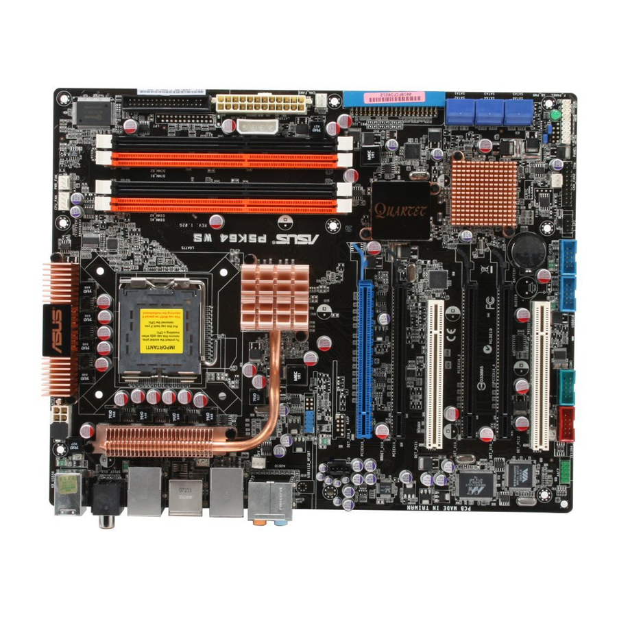
Page 29: Motherboard Layout
88E8001 PCIEX16_4 VIA 6308S PCI2 IE1394_2 COM1 AAFP Refer to 2.7 Connectors for more information about rear panel connectors and internal connectors. ASUS P5K64 WS 24.5cm (9.6in) LGA775 Intel MCH Bearlake P35 9LPRS918BKL Intel ICH9R CR2032 3V Lithium Cell CMOS Power... -
Page 30: Layout Contents
2.2.4 Layout contents Slots DDR3 DIMM slots PCI slots PCI Express slots Jumper Clear RTC RAM (3-pin CLRTC) Rear panel connectors PS/2 keyboard port (purple) Coaxial S/PDIF Out port LAN 1 (RJ-45) port IEEE 1394a port LAN 2 (RJ-45) port Center/Subwoofer port (orange) Rear Speaker Out port (black) Line In port (light blue) - Page 31 Front panel audio connector (10-1 pin AAFP) Optical drive audio connector (4-pin CD) Serial port connetor (10-1 pin COM1) TPM connectors (20-1 pin TPM) System panel connector (20-8 pin PANEL) ASUS Q-connector (system panel) ASUS P5K64 WS Page 2-22 2-22...
-
Page 32: Central Processing Unit (Cpu)
ASUS will shoulder the cost of repair only if the damage is shipment/transit-related. • Keep the cap after installing the motherboard. ASUS will process Return Merchandise Authorization (RMA) requests only if the motherboard comes with the cap on the LGA775 socket. -
Page 33: Installing The Cpu
Installing the CPU To install a CPU: Locate the CPU socket on the motherboard. P5K64 WS CPU Socket 775 Before installing the CPU, make sure that the cam box is facing towards you and the load lever is on your left. - Page 34 Lift the load plate with your thumb and forefinger to a 100º angle (A), then push the PnP cap from the load plate window to remove (B). Position the CPU over the socket, making sure that the gold triangle is on the bottom-left corner of the socket then fit the socket alignment key into the...
-
Page 35: Installing The Cpu Heatsink And Fan
CPU fan connector. Make sure to orient each fastener with the narrow end of the groove pointing outward. (The photo shows the groove shaded for emphasis.) ASUS P5K64 WS processor, the package includes the CPU fan ® ®... - Page 36 Connect the CPU fan cable to the connector on the motherboard labeled CPU_FAN. P5K64 WS CPU Fan Connector DO NOT forget to connect the CPU fan connector! Hardware monitoring errors can occur if you fail to plug this connector.
-
Page 37: Uninstalling The Cpu Heatsink And Fan
Carefully remove the heatsink a n d f a n a s s e m b l y f r o m t h e motherboard. ASUS P5K64 WS 2-11... - Page 38 Rotate each fastener clockwise to ensure correct orientation when reinstalling. T h e n a r r o w e n d o f t h e groove should point outward after resetting. (The photo shows the groove shaded for emphasis.) Refer to the documentation in the boxed or stand-alone CPU fan package for detailed information on CPU fan installation.
-
Page 39: System Memory
P5K64 WS 240-pin DDR3 DIMM Sockets Channel Channel A Channel B This chipset officially supports DDR3 1066/800. With the ASUS Super Memspeed Technology, the motherboard supports up to 1333MHz and provides more ratio setting items than the chipset officially supports. Refer to the table below for details. - Page 40 • Always install DIMMs with the same CAS latency. For optimum compatibility, it is recommended that you obtain memory modules from the same vendor. Refer to the DDR3 Qualified Vendors List at the ASUS web site. • Due to chipset resource allocation, the system may detect less than 8 GB system memory when you installed four 2 GB DDR3 memory modules.
-
Page 41: Installing A Dimm
Support the DIMM lightly with your fingers when pressing the retaining clips. The DIMM might get damaged when it flips out with extra force. Remove the DIMM from the socket. ASUS P5K64 WS DDR3 DIMM notch Unlocked retaining clip DDR3 DIMM notch 2-15... -
Page 42: Expansion Slots
Expansion slots In the future, you may need to install expansion cards. The following sub-sections describe the slots and the expansion cards that they support. Make sure to unplug the power cord before adding or removing expansion cards. Failure to do so may cause you physical injury and damage motherboard components. -
Page 43: Standard Interrupt Assignments
PCI slot 2 LAN(8052) LAN(8001) Marvell 6121 PCIE x16 1 PCIE x16 2 PCIE x16 3 PCIE x16 4 USB controller 1 USB controller 2 USB controller 3 USB controller 4 USB controller 5 USB controller 6 EHCI 1 EHCI 2 SATA controller 1 SATA controller 2 Azalia ASUS P5K64 WS Standard Function System Timer Keyboard Controller Re-direct to IRQ#9 IRQ holder for PCI steering* Communications Port (COM1)* IRQ holder for PCI steering* Floppy Disk Controller PCI device System CMOS/Real Time Clock IRQ holder for PCI steering* IRQ holder for PCI steering* IRQ holder for PCI steering* PS/2 Compatible Mouse Port* Numeric Data Processor PCI device PCI device —... -
Page 44: Pci Slots
2.5.4 PCI slots The PCI slots support cards such as a LAN card, SCSI card, USB card, and other cards that comply with PCI specifications. The figure shows a LAN card installed on a PCI slot. 2.5.5 PCI Express slots This motherboard has four PCI Express slots that support PCI Express graphic cards complying with the PCI Express... -
Page 45: Clear Rtc Ram (Clrtc)
Except when clearing the RTC RAM, never remove the cap on CLRTC jumper default position. Removing the cap will cause system boot failure! P5K64 WS Clear RTC RAM • You do not need to clear the RTC when the system hangs due to overclocking. -
Page 46: Connectors
Connectors 2.7.1 Rear panel connectors PS/2 keyboard port (purple). This port is for a PS/2 keyboard. Coaxial S/PDIF Out port. This port connects an external audio output device via a coaxial S/PDIF cable. LAN 1 (RJ-45) port. This port allows Gigabit connection to a Local Area Network (LAN) through a network hub. - Page 47 The external SATA port supports external Serial ATA 3.0 Gb/s devices. Longer cables support higher power requirements to deliver signal up to two meters away, and enables improved hot- swap function. ASUS P5K64 WS 4-channel 6-channel Line In Line In Front Speaker Out Mic In Mic In –...
-
Page 48: Internal Connectors
Pin 5 on the connector is removed to prevent incorrect cable connection when using a FDD cable with a covered Pin 5. P5K64 WS F IDE connector (40-1 pin PRI_E IDE) The onboard IDE connector is for the Ultra DMA 133/100/66 signal cable. - Page 49 P5K64 WS IDE Connector ICH9R Serial ATA connectors (7-pin SATA1 [blue], SATA2 [blue], SATA3 [blue], SATA4 [blue], SATA5 [blue], SATA6 [blue]) These connectors are for the Serial ATA signal cables for Serial ATA hard disk drives. If you installed Serial ATA hard disk drives, you can create a RAID 0 and...
- Page 50 If your chassis suppots front panel USB ports, you can attach a front panel USB cable to these connectors. Connect the USB cable to ASUS Q-Connector (USB, blue) first, and then install the Q-Connector (USB) to the USB connector onboard.
- Page 51 You can attach a FireWire/1394 cable to this connector if your chassis suppots the front panel IEEE1394 port. Connect the 1394 cable to ASUS Q-Connector (1394, red) first, and then install the Q-Connector (1394) to the 1394 connector onboard.
- Page 52 Do not place jumper caps on the fan connectors! P5K64 WS Fan Connectors • Only the CPU-FAN and CHA-FAN 1-2 connectors support the ASUS Advanced Q-Fan feature. • If you install two VGA cards, we recommend that you plug the rear chassis fan cable to the motherboard connector labled CHA_FAN1 or CHA_FAN2 for better themal environment.
-
Page 53: Chassis Intrusion Connector
Find the proper orientation and push down firmly until the connectors completely fit. P5K64 WS ATX Power Connector • Make sure to remove the cap on the EATX12V connector before connecting an 8-pin EPS +12V power plug. - Page 54 HD Audio or legacy AC`97 audio standard. Connect one end of the front panel audio I/O module cable to this connector. P5K64 WS Front Panel Audio Connector • We recommend that you connect a high-definition front panel audio module to this connector to avail of the motherboard’s high-definition audio...
- Page 55 This connector allows you to receive stereo audio input from sound sources such as a CD-ROM, TV tuner, or MPEG card. P5K64 WS Internal Audio Connector 11. Serial port connector (10-1 pin COM1) This connector is for a serial (COM) port. Connect the serial port module cable to this connector, then install the module to a slot opening at the back of the system chassis.
-
Page 56: System Panel Connector 20-8 Pin Panel
13. System panel connector (20-8 pin PANEL) This connector supports several chassis-mounted functions. System Panel Connector P5K64 WS • System power LED (2-pin PLED) This 2-pin connector is for the system power LED. Connect the chassis power LED cable to this connector. The system power LED lights up when you turn on the system power, and blinks when the system is in sleep mode. -
Page 57: Asus Q-Connector
ASUS Q-Connector (system panel) You can use the ASUS Q-Connector to connect/disconnect chassis front panel cables in a few steps. Refer to the instructions below to install the ASUS Q- Connector. Connect the front panel cables to the ASUS Q-Connector. -
Page 58: Installing The Optional Fan
2.7.3 Installing the optional fan Install the optional fan only if you are using a passive cooler or a water cooler. Installing the optional fan with an active CPU cooler will interfere with the airflow and destabilize the system. Position the fan above the pipe and heatsink assembly. -
Page 59: Chapter 3: Powering Up
This chapter describes the power up sequence, the vocal POST messages, and ways of shutting down the system. Powering up... -
Page 60: Starting Up For The First Time
Chapter summary Starting up for the first time ... 3-1 Turning off the computer ... 3-2 ASUS P5K64 WS... -
Page 61: Starting Up For The First Time
One continuous beep followed by four short beeps At power on, hold down the <Delete> key to enter the BIOS Setup. Follow the instructions in Chapter 4. ASUS P5K64 WS Description VGA detected Quick boot set to disabled No keyboard detected... -
Page 62: Turning Off The Computer
Turning off the computer 3.2.1 Using the OS shut down function If you are using Windows Click the Start button then select Turn Off Computer. Click the Turn Off button to shut down the computer. The power supply should turn off after Windows If you are using Windows Click the Start button then select ShutDown. -
Page 63: Chapter 4: Bios Setup
This chapter tells how to change the system settings through the BIOS Setup menus. Detailed descriptions of the BIOS parameters are also provided. BIOS setup... - Page 64 Chapter summary Managing and updating your BIOS ... 4-1 BIOS setup program ... 4-8 Main menu ... 4-11 Advanced menu ... 4-15 Power menu ... 4-26 Boot menu ... 4-31 Tools menu ... 4-35 Exit menu ... 4-37 ASUS P5K64 WS...
-
Page 65: Managing And Updating Your Bios
Input/Output System (BIOS) setup. ASUS Update (Updates the BIOS in Windows ASUS EZ Flash 2 (Updates the BIOS using a floppy disk or USB flash disk.) ASUS AFUDOS (Updates the BIOS using a bootable floppy disk) ASUS CrashFree BIOS 3 (Updates the BIOS using a bootable floppy disk, USB flash disk or the motherboard support DVD when the BIOS file fails or gets corrupted.) - Page 66 Updating the BIOS through the Internet To update the BIOS through the Internet: Launch the ASUS Update utility from the Windows > Programs > ASUS > ASUSUpdate > ASUSUpdate. The ASUS Update main window appears. Select Update BIOS from the Internet option from the drop-down menu, then click Next.
- Page 67 Updating the BIOS through a BIOS file To update the BIOS through a BIOS file: Launch the ASUS Update utility from the Windows > Programs > ASUS > ASUSUpdate > ASUSUpdate. The ASUS Update main window appears. Select Update BIOS from a file option from the drop-down menu, then click Next.
-
Page 68: Asus Ez Flash 2 Utility
4.1.2 ASUS EZ Flash 2 utility The ASUS EZ Flash 2 feature allows you to update the BIOS without having to go through the long process of booting from a floppy disk and using a DOS-based utility. The EZ Flash 2 utility is built-in the BIOS chip so it is accessible by pressing <Alt>... -
Page 69: Afudos Utility
The utility returns to the DOS prompt after copying the current BIOS file. Updating the BIOS file To update the BIOS file using the AFUDOS utility: Visit the ASUS website (www.asus.com) and download the latest BIOS file for the motherboard. Save the BIOS file to a bootable floppy disk. ASUS P5K64 WS... - Page 70 A:\>afudos /iP5K64WS.ROM The utility verifies the file and starts updating the BIOS. A:\>afudos /iP5K64WS.ROM AMI Firmware Update Utility - Version 1.19(ASUS V2.07(03.11.24BB)) Copyright (C) 2002 American Megatrends, Inc. All rights reserved. WARNING!! Do not turn off power during flash BIOS Reading file ... done Reading flash ...
-
Page 71: Asus Crashfree Bios 3 Utility
4.1.4 ASUS CrashFree BIOS 3 utility The ASUS CrashFree BIOS 3 is an auto recovery tool that allows you to restore the BIOS file when it fails or gets corrupted during the updating process. You can update a corrupted BIOS file using the motherboard support DVD, the floppy disk, or the USB flash disk that contains the updated BIOS file. -
Page 72: Bios Setup Program
The BIOS setup screens shown in this section are for reference purposes only, and may not exactly match what you see on your screen. • Visit the ASUS website (www.asus.com) to download the latest BIOS file for this motherboard. Chapter 4: BIOS setup... -
Page 73: Bios Menu Screen
At the bottom right corner of a menu screen are the navigation keys for that particular menu. Use the navigation keys to select items in the menu and change the settings. The navigation keys may differ from one screen to another. ASUS P5K64 WS Configuration fields BIOS SETUP UTILITY Boot... -
Page 74: Menu Items
4.2.4 Menu items The highlighted item on the menu bar displays the specific items for that menu. For example, selecting Main shows the Main menu items. The other items (Advanced, Power, Boot, and Exit) on the menu bar have their respective menu items. 4.2.5 Sub-menu items A solid triangle before each item on any menu screen means that the iteam has a... -
Page 75: Main Menu
Configuration options: [Disabled] [720K , 3.5 in.] [1.44M, 3.5 in.] 4.3.4 Language [English] Allows you to select the display language for the BIOS setup screen. Configuration options: [Chinese(BIG5)] [Chinese(GB)] [Japanese] [Français] [German] [English] ASUS P5K64 WS BIOS SETUP UTILITY Boot Tools Exit [10:55:25] [Mon 04/23/2007] [1.44M, 3.5 in.]... -
Page 76: Sata 1-6
4.3.5 SATA 1-6 While entering Setup, the BIOS automatically detects the presence of Serial ATA devices. There is a separate sub-menu for each SATA device. Select a device item then press <Enter> to display the SATA device information. Main SATA 1 Device : Hard Disk Vendor... -
Page 77: Sata Configuration
If you want to use the Serial ATA hard disk drives as Parallel ATA physical storage devices, keep the default setting [IDE]. If you want the Serial ATA hard disk drives to use the Advanced Host Controller Interface (AHCI), set this item to [AHCI]. ASUS P5K64 WS [Enhanced] [IDE] [Disabled]... -
Page 78: System Information
Intel Robson Technology [Disabled] Allows you to enable or disable Intel Robson Technology. Configuration option: [Disabled] [Enabled] The Intel Robson Technology appears only when you set the item Configure SATA as to [AHCI]. Hard Disk Write Protect [Disabled] Disables or enables device write protection. This will be effective only if the device is accessed through BIOS. -
Page 79: Advanced Menu
Allows you to individually set overclocking parameters. Loads the optimal settings for the system. Loads the standard settings for the system. The ASUS Non-delay Overclocking System feature intelligently determines the system load and automatically boosts the performance for the most demanding tasks. - Page 80 The following item only appears when you set the Ai Overclocking item to [N.O.S]. N.O.S. Mode [Auto] Configuration options: [Auto] [Standard] [Sensitive] [Heavy Load] CPU Ratio Control [Auto] Allows you to control the CPU ratio. Configuration options: [Auto] [Manual] The following item only appears when you set the CPU Ratio Control item to [Manual].
-
Page 81: Dram Static Read Control [Auto]
Transaction Booster [Auto] Configuration options: [Auto] [Enabled] Clock Over-Charging Mode [Auto] Configuration options: [Auto] [700mV] [800mV] [900mV] [1000mV] CPU Spread Spectrum [Auto] Allows you to enable or disable the CPU spread spectrum. Configuration options: [Auto] [Disabled] ASUS P5K64 WS 4-17... - Page 82 PCIE Spread Spectrum [Auto] Allows you to enable or disable the PCIE spread spectrum. Configuration options: [Auto] [Disabled] The following items appear when you set the Ai Overclocking item to [Manual] and [N.O.S]. CPU Voltage [Auto] Allows you to select the CPU VCore voltage. Configuration options: [Auto] [1.7000V] [1.6875V] [1.6750V] [1.6625V] [1.6500V] [1.6375V] [1.6250V] [1.6125V] [1.6000V] [1.5875V] [1.5750V] [1.5625V] [1.5500V] [1.5375V] [1.5250V] [1.5125V] [1.5000V] [1.4875V] [1.4750V] [1.4625V] [1.4500V]...
-
Page 83: Ai Net2
Allows you to enable or disable LAN cable check during POST. When enabled, the menu reports the cable faults or shorts, and displays the point (length) where the fault or short is detected. Confirguration options: [Disabled] [Enabled] You must reboot after changing the setting. ASUS P5K64 WS BIOS SETUP UTILITY [Disabled] [Disabled]... -
Page 84: Usb Configuration
4.4.3 USB Configuration The items in this menu allows you to change the USB-related features. Select an item then press <Enter> to display the configuration options. Advanced USB Configuration USB Devices Enabled: 1 Mouse USB Functions USB 2.0 Controller USB 2.0 Controller Mode BIOS EHCI Hand-off Port 64/60 Emulation Legacy USB Support... -
Page 85: Bios Ehci Hand-Off [Enabled]
[Auto] allows the system to detect the presence of USB devices at startup. If detected, the USB controller legacy mode is enabled. If no USB device is detected, the legacy USB support is disabled. Configuration options: [Disabled] [Enabled] [Auto] ASUS P5K64 WS 4-21... -
Page 86: Cpu Configuration
4.4.4 CPU Configuration The items in this menu show the CPU-related information that the BIOS automatically detects. Advanced Configure advanced CPU settings Manufacturer: Intel Brand String: Genuine Intel(R) CPU 2.80GHz Frequency : 2.81GHz FSB Speed : 800 MHz Cache L1 : 32 KB Cache L2 : 2048 KB... -
Page 87: Chipset
PEG Port Control [Auto] Configuration options: [Auto] [Disabled] The following item appears only when you set PEG Port Control to [Auto] PEG Port Force x1 [Disabled] Configuration options: [Enabled] [Disabled] ASUS P5K64 WS BIOS SETUP UTILITY BIOS SETUP UTILITY [Enabled] [PEG/PCI]... -
Page 88: Onboard Devices Configuration
4.4.6 OnBoard Devices Configuration Advanced Onboard Device Configuration High Definition Audio Front Panel Type Marvell IDE/eSATA IDE/eSATA Boot ROM PCEI GigaBit LAN1 LAN Boot ROM PCI GigaBit LAN2 LAN Boot ROM Firewire 1394 Serial Port1 Address v02.58 (C)Copyright 1985-2007, American Megatrends, Inc. High Definition Audio [Enabled] Allows you to enable or disable the High Definition Audio Controller. -
Page 89: Serial Port1 Address [3F8/Irq4]
When set to [NO], BIOS configures all the devices in the system. When set to [YES] and if you install a Plug and Play operating system, the operating system configures the Plug and Play devices not required for boot. Configuration options: [NO] [YES] ASUS P5K64 WS BIOS SETUP UTILITY [NO] NO: lets the BIOS configure all the devices in the system. -
Page 90: Power Menu
Power menu The Power menu items allow you to change the settings for the Advanced Power Management (APM). Select an item then press <Enter> to display the configuration options. Main Advanced Suspend Mode Repost Video on S3 Resume ACPI 2.0 Support ACPI APIC Support APM Configuration Hardware Monitor... -
Page 91: Apm Configuration
Allows you to enable or disable the PME to wake up from S5 by PCI devices. Configuration options: [Disabled] [Enabled] Power On By PCIE Devices [Disabled] Allows you to enable or disable the PCIE devices to generate a wake event. Configuration options: [Disabled] [Enabled] ASUS P5K64 WS BIOS SETUP UTILITY Power [Power Off]... -
Page 92: Hardware Monitor
Voltage v02.58 (C)Copyright 1985-2007, American Megatrends, Inc. AI Quiet [Disabled] Allows you to enable or disable the ASUS AI Quiet feature. ASUS AI Quiet optimizes system performance by automatically adjusting the CPU fan speed according to the system loading. Configuration options: [Disabled] [Enabled] CPU Temperature [xxxºC/xxxºF]... -
Page 93: Chassis Q-Fan Control [Disabled]
Configuration options: [Optimal] [90%] [80%] [70%] [60%] Chassis Target Temperature [37ºC] The CPU fan speed will be adjusted to maintain the CPU temperature as low as the selected temperature. Configuration options: [28ºC] [31ºC] [34ºC] [37ºC] [40ºC] [43ºC] [46ºC] ASUS P5K64 WS ’s PWM fan ® 4-29... - Page 94 Power Fan Speed (RPM) [xxxxRPM] or [Ignored] / [N/A] The onboard hardware monitor automatically detects and displays the power fan speed in rotations per minute (RPM). If the fan is not connected to the motherboard, the field shows N/A. Vcore Voltage, 3.3V Voltage, 5V Voltage, 12V Voltage The onboard hardware monitor automatically detects the voltage output through the onboard voltage regulators.
-
Page 95: Boot Menu
These items specify the boot device priority sequence from the available devices. The number of device items that appears on the screen depends on the number of devices installed in the system. Configuration options: [xxx Drive] [Disabled] ASUS P5K64 WS BIOS SETUP UTILITY Boot... -
Page 96: Boot Settings Configuration
This allows you to enable or disable the full screen logo display feature. Configuration options: [Disabled] [Enabled] Set this item to [Enabled] to use the ASUS MyLogo3™ feature. AddOn ROM Display Mode [Force BIOS] Sets the display mode for option ROM. -
Page 97: Security
Time Clock (RTC) RAM. See section 2.6 Jumper for information on how to erase the RTC RAM. After you have set a supervisor password, the other items appear to allow you to change other security settings. ASUS P5K64 WS BIOS SETUP UTILITY Boot <Enter> to change password. -
Page 98: Change User Password
Security Settings Supervisor Password User Password Change Supervisor Password User Access Level Change User Password Clear User Password Password Check v02.58 (C)Copyright 1985-2007, American Megatrends, Inc. User Access Level [Full Access] This item allows you to select the access restriction to the Setup items. Configuration options: [No Access] [View Only] [Limited] [Full Access] [No Access] prevents user access to the Setup utility. -
Page 99: Tools Menu
4.7.1 ASUS EZ Flash 2 Allows you to run ASUS EZ Flash 2. When you press <Enter>, a confirmation message appears. Use the left/right arrow key to select between [Yes] or [No], then press <Enter> to confirm your choice. Please see page 4-4, section 4.1.2 for details. -
Page 100: Asus O.c. Profile
4.7.2 ASUS O.C. Profile This item allows you to store or load multiple BIOS settings. O.C. PROFILE Configuration O.C. Profile 1 Status O.C. Profile 2 Status Save to Profile Load from Profile 1 Save to Profile 2 Load from Profile 2 Start O.C. -
Page 101: Exit Menu
Setup menus. When you select this option or if you press <F5>, a confirmation window appears. Select YES to load default values. Select Exit & Save Changes or make other changes before saving the values to the non-volatile RAM. ASUS P5K64 WS BIOS SETUP UTILITY Boot... - Page 102 4-38 Chapter 4: BIOS setup...
-
Page 103: Chapter 5: Software Support
This chapter describes the contents of the support CD that comes with the motherboard package. Software support... -
Page 104: Chapter Summary
Chapter summary Installing an operating system ... 5-1 Support DVD information ... 5-1 Software information ... 5-9 RAID configurations ... 5-28 Creating a RAID driver disk ... 5-39 ASUS P5K64 WS... -
Page 105: Installing An Operating System
The contents of the support DVD are subject to change at any time without notice. Visit the ASUS website(www.asus.com) for updates. 5.2.1 Running the support DVD Place the support DVD to the optical drive. The DVD automatically displays the Drivers menu if Autorun is enabled in your computer. -
Page 106: Drivers Menu
The drivers menu shows the available device drivers if the system detects installed devices. Install the necessary drivers to activate the devices. ASUS InstAll-Installation Wizard for Drivers Installs the ASUS InstAll-Drivers Installation Wizard. Intel Chipset Inf Update Program Installs the Intel chipset Inf update program. -
Page 107: Utilities Menu
Installs the ASUS AI Suite. ASUS Update Allows you to download the latest version of the BIOS from the ASUS website. Before using the ASUS Update, make sure that you have an Internet connection so you can connect to the ASUS website. - Page 108 Adobe Acrobat Reader V7.0 Installs the Adobe Acrobat Reader that allows you to open, view, and print ® ® documents in Portable Document Format (PDF). Microsoft DirectX 9.0c Installs the Microsoft DirectX 9.0 driver. The Microsoft DirectX 9.0 is a multimedia ®...
-
Page 109: Make Disk Menu
Make Intel ICH9R AHCI/RAID 32bit/64bit Driver Allows you to create an Intel ICH9R RAID driver disk for a 32/64-bit system. ® Make Marvell 61xx PATA/eSATA Driver Allows you to create a Marvell 61xx PATA/eSATA driver disk. ® ASUS P5K64 WS... -
Page 110: Manual Menu
5.2.6 ASUS Contact information Click the Contact tab to display the ASUS contact information. You can also find this information on the inside front cover of this user guide. Reader from the Utilities tab before opening a user manual ®... -
Page 111: Other Information
The icons on the top right corner of the screen give additional information on the motherboard and the contents of the support DVD. Click an icon to display the specified information. Motherboard Info Displays the general specifications of the motherboard. Browse this DVD Displays the support DVD contents in graphical format. ASUS P5K64 WS... -
Page 112: Technical Support Form
Technical support Form Displays the ASUS Technical Support Request Form that you have to fill out when requesting technical support. Filelist Displays the contents of the support DVD and a brief description of each in text format. Chapter 5: Software support... -
Page 113: Software Information
5.3.1 ASUS MyLogo2™ The ASUS MyLogo2™ utility lets you customize the boot logo. The boot logo is the image that appears on screen during the Power-On Self-Tests (POST). The ASUS MyLogo2™ is automatically installed when you install the ASUS Update utility from the Support DVD. - Page 114 Ratio box. When the screen returns to the ASUS Update utility, flash the original BIOS to load the new boot logo. 10. After flashing the BIOS, restart the computer to display the new boot logo during POST.
-
Page 115: Audio Configurations
Realtek HD Audio Manager. Realtek HD Audio Manager Configuration options Control settings window Information button ASUS P5K64 WS ® (Universal Audio Jack) technology for all ® Audio Driver from the support Realtek HD Audio Manager Exit button Minimize... -
Page 116: Configuration Options
Information Click the information button ( display information about the audio driver version, DirectX version, audio controller, audio codec, and language setting. Minimize Click the minimize button ( Exit Click the exit button ( Configuration options Click any of the tabs in this area to configure your audio settings. Sound Effect The Realtek ALC888 Audio CODEC... - Page 117 The control settings window displays the status of connected devices. Click for analog and digital options. Click <OK> to effect the Audio I/O settings and exit ASUS P5K64 WS ) if you do not want voice input. 5-13...
- Page 118 Microphone The Microphone option allows you configure your input/output settings and to check if your audio devices are connected properly. To set the Microphone options: From the Realtek HD Audio Manager, click the Microphone tab. Click the Noise Suppression option button to reduce the static background noise when recording. Click the Acoustic Echo Cancellation option button to reduce the echo from the front speakers when recording.
-
Page 119: Asus Pc Probe Ii
® To launch the PC Probe II from the Windows > ASUS > PC Probe II > PC Probe II v1.xx.xx. The PC Probe II main window appears. After launching the application, the PC Probe II icon appears in the Windows taskbar. - Page 120 Button Sensor alert When a system sensor detects a problem, the main window right handle turns red, as the illustrations below show. When displayed, the monitor panel for that sensor also turns red. Refer to the Monitor panels section for details. Preferences You can customize the application using the Preference section in the main window.
- Page 121 You can also adjust the threshold values using the Config window. You cannot adjust the sensor threshold values in a small monitoring panel. ASUS P5K64 WS Small display Click to increase value Click to decrease...
-
Page 122: Dmi Browser
Monitoring sensor alert The monitor panel turns red when a component value exceeds or is lower than the threshold value. Refer to the illustrations below. Large display WMI browser Click to display the WMI (Windows Management Instrumentation) browser. This browser displays various Windows® management information. - Page 123 Click a hard disk drive to display the information on the right panel. The pie chart at the bottom of the window represents the used (blue) and the available HDD space. ASUS P5K64 WS to display the Usage browser. 5-19...
- Page 124 Memory usage The Memory tab shows both used and available physical memory. The pie chart at the bottom of the window represents the used (blue) and the available Configuring PC Probe II Click to view and adjust the sensor threshold values. The Config window has two tabs: Sensor/Threshold and Preference.
-
Page 125: Asus Ai Suite
5.3.4 ASUS AI Suite ASUS AI Suite allows you to launch AI Gear2, AI N.O.S., AI Booster, AI Nap, and Q-Fan2 utilities easily. Installing AI Suite To install AI Suite on your computer: Place the support DVD to the optical drive. The Drivers installation tab appears if your computer has an enabled Autorun feature. - Page 126 Other feature buttons Click on right corner of the main window to open the monitor window. Click on right corner of the expanded window to switch the temperature from degrees Centigrade to degrees Fahrenheit. 5-22 Displays the CPU/ system temperature, CPU/memory/PCIE voltage, and CPU/ chassis fan speed...
-
Page 127: Asus Ai Gear2
5.3.5 ASUS AI Gear2 ASUS AI Gear2 provides four system performance options that allows you to select the best performance setting for your computing needs. This easy-to-use utility adjusts the processor frequency and vCore voltage to minimize system noise and power consumption. -
Page 128: Asus Ai Nap
5.3.6 ASUS AI Nap This feature allows you to minimize the power consumption of your computer whenever you are away. Enable this feature for minimum power consumption and a more quiet system operation. After installing AI Suite from the bundled support DVD, you can launch the utility by double-clicking the AI Suite icon on the Windows OS taskbar and click the AI Nap button on the AI Suite main window. -
Page 129: Asus Ai N.o.s
5.3.7 ASUS AI N.O.S. This ASUS Non-delay Overclocking System feature intelligently determines the system load and automatically boosts the performance for the most demanding tasks. After installing AI Suite from the bundled support DVD, you can launch the utility by double-clicking the AI Suite icon on the Windows OS taskbar and click the AI N.O.S. -
Page 130: Asus Q-Fan2
5.3.8 ASUS Q-Fan2 This ASUS Q-Fan2 Control feature allows you to set the appropriate performance level of the CPU Q-Fan2 or the Chassis Q-Fan2 for more efficient system operation. After enabling the Q-Fan2 function, the fans can be set to automatically adjust depending on the temperature, to decrease fan speed, or to achieve the maximum fan speed. -
Page 131: Asus Ai Booster
5.3.9 ASUS AI Booster The ASUS AI Booster application allows you to overclock the CPU speed in WIndows environment without the hassle of booting the BIOS. ® After installing AI Suite from the bundled support DVD, you can launch the utility... -
Page 132: Raid Configurations
RAID configurations The motherboard comes with two RAID controllers that allow you to configure Serial ATA hard disk drives as RAID sets. The Intel ICH9R Southbridge RAID includes a high performance SATA • ® RAID controller that supports RAID 0, RAID 1, RAID 10, and RAID 5 for six independent Serial ATA channels. -
Page 133: Installing Serial Ata Hard Disks
Select the item Onboard Serial-ATA BOOTROM, press <Enter>, then select Enabled from the options. Save your changes, then exit the BIOS Setup. See Chapter 4 for details on entering and navigating through the BIOS Setup. ASUS P5K64 WS Matrix ® ICH9R ®... -
Page 134: Intel ® Matrix Storage Manager Option Rom Utility
Intel Matrix Storage Manager Option ROM Utility ® The Intel Matrix Storage Manager Option ROM utility allows you to create RAID 0, ® RAID 1, RAID 10 (RAID 0+1), and RAID 5 set(s) from Serial ATA hard disk drives that are connected to the Serial ATA connectors supported by the Southbridge. -
Page 135: Creating A Raid 0 Set (Striped)
Select 2 to 4 disks to use in creating the volume. [↑↓]-Previous/Next Use the up/down arrow key to highlight a drive, then press <Space> to select. A small triangle marks the selected drive. Press <Enter> after completing your selection. ASUS P5K64 WS [ CREATE ARRAY MENU ] Name: Volume0... - Page 136 Use the up/down arrow key to select the stripe size for the RAID 0 array, then press <Enter>. The available stripe size values range from 4 KB to 128 KB. The default stripe size is 128 KB. TIP: We recommend a lower stripe size for server systems, and a higher stripe size for multimedia computer systems used mainly for audio and video editing.
- Page 137 WARNING: ALL DATA ON SELECTED DISKS WILL BE LOST. Are you sure you want to create this volume? (Y/N): Press <Y> to create the RAID volume and return to main menu or <N> to go back to Create Volume menu. ASUS P5K64 WS [ CREATE ARRAY MENU Name: Volume1...
-
Page 138: Creating A Raid 10 Set
Creating a RAID 10 set To create a RAID 10 set: From the utility main menu, select 1. Create RAID Volume, then press <Enter>. This screen appears. Intel(R) Matrix Storage Manager Option ROM v5.0.0.1032 ICH7R wRAID5 Copyright(C) 2003-05 Intel Corporation. All Rights Reserved. Enter a string between 1 and 16 characters in length that can be used to uniquely identify the RAID volume. - Page 139 RAID. The following pop-up screen appears. Port Drive Model 0 XXXXXXXXXXXX 1 XXXXXXXXXXXX 2 XXXXXXXXXXXX 3 XXXXXXXXXXXX Select 2 to 4 disks to use in creating the volume. [↑↓]-Previous/Next ASUS P5K64 WS [ CREATE ARRAY MENU Name: Volume5 RAID5(Parity) Disks: Select Disks 64KB...
- Page 140 Use the up/down arrow key to highlight the drive you want to set, then press <Space> to select. A small triangle marks the selected drive. Press <Enter> after completing your selection. When the Stripe Size item is highlighted, press the up/down arrow key to select the stripe size for the RAID 5 array, then press <Enter>.
-
Page 141: Deleting A Raid Set
Are you sure you want to delete volume “VolumeX”? (Y/N): Press <Y> to delete the RAID set and return to the utility main menu; otherwise, press <N> to return to the Delete Volume menu. ASUS P5K64 WS [ DELETE VOLUME MENU Drives Capacity XXX.XGB... -
Page 142: Resetting Disks To Non-Raid
Resetting Disks to Non-RAID Take caution before you reset a RAID volume HDD to non-RAID. Resetting a RAID volume HDD deletes all internal RAID structure on the drive. To reset a RAID set hard disk drive: From the utility main menu, select 3. Reset Disks to Non-RAID, then press <Enter>... -
Page 143: Creating A Raid Driver Disk
88SE61xx SATA RAID driver disk. Insert a floppy disk/USB device into the floppy disk drive/USB port. Follow succeeding screen instructions to complete the process. Write-protect the floppy disk to avoid computer virus infection. ASUS P5K64 WS environment: ® ® ®... - Page 144 To install the RAID driver in Windows During the OS installation, the system prompts you to press the F6 key to install third-party SCSI or RAID driver. Press <F6> then insert the floppy disk with RAID driver into the floppy disk drive.
-
Page 145: Chapter 6: Ati Crossfire™ Technology Support
This chapter tells how to install ATI ® CrossFire™ graphics cards to avail of ATI’s Multi-Video Processing technology. CrossFire™ ® technology support... -
Page 146: Chapter Summary
Chapter summary Overview ... 6-1 Installing CrossFire™ graphics cards ... 6-2 Software information ... 6-5 ASUS P5K64 WS... -
Page 147: Overview
Close all current applications. Go to Control Panel > Add/Remove Programs. Select your current graphics card driver/s. Select Add/Remove. Restart your system. ASUS P5K64 WS CrossFire™ technology that allows you to ® XP 32-bit (Home or Professional) with Service ®... -
Page 148: Installing Crossfire™ Graphics Cards
Installing CrossFire™ graphics cards Before installing a CrossFire™ system, refer to the user guide that came with the ATI CrossFire™ Edition graphics card. ® To install the graphics cards: Prepare one CrossFire™ Edition (Master) graphics card and one CrossFire™-ready (Slave) graphics card. Slave graphics card Insert the CrossFire™... - Page 149 Insert the CrossFire™-ready (Slave) graphics card into the PCI Express x16 black slot. Make sure that the card is properly seated on the slot. Connect an auxiliary power source from the power supply to the graphics cards. ASUS P5K64 WS...
- Page 150 Connect one end of the external cable to the Master graphics card. Connect the other end of the external cable to the Slave graphics card. Connect the loose end to the corresponding port on your monitor. Chapter 6: ATI MVP technology support ®...
-
Page 151: Software Information
Click Next to continue from the installation window that appears. Read the License Agreement, then click Yes. ASUS P5K64 WS XP 32-bit (Home or Professional) with Service ® XP Professional 64-bit Edition. ® Vista 32/64 bit Edition. (Will be ready later. Visit the ATI... - Page 152 Select the components that you want to install, then click Next. • Select Express to install the HydraVision™ multi-monitor and desktop management software, as well as the ATI driver. • Select Custom to individually choose desired software components. Setup prepares the installation wizard that will guide you to setup process.
-
Page 153: Using The Catalyst™ Control Center
Start > ATI Catalyst™ Control Center > • On the Windows ® Catalyst™ Control Center • Double-click the Catalyst™ Control Center desktop shortcut. • On the Windows task bar, double- ® click the Catalyst™ Control Center icon. ASUS P5K64 WS... -
Page 154: The Catalyst™ Control Center Dialog Box
The Catalyst™ Control Center Dialog Box View The Catalyst™ Control Center provides two views: Standard - simple view with wizards for beginners Advance - allows advanced users to access and configure the complete features of the software Set to Advance view to enable the CrossFire™ function. Chapter 6: ATI MVP technology support ®... - Page 155 In the CrossFire™ Settings dialog, tick the box opposite Enable CrossFire™. Click OK to effect the setting. Hotkeys Click the Hotkeys tab on the Catalyst™ Control Center to access the Hotkeys Manager, which allows you to create key combinations as shortcuts for performing certain functions quickly. ASUS P5K64 WS...
- Page 156 Profiles Click the Profiles tab on the Catalyst™ Control Center to access the Profiles Manager, which allows you to create customized environments for your desktop, video, and 3D applications. Preferences Click the Preferences tab on the Catalyst™ Control Center to select a language, restore defaults, change skins, or enable/disable the System Tray icon.
- Page 157 Help Click the Help tab on the Catalyst™ Control Center to access the online help system, generate a Problem Report, and get the Catalyst™ Control Center version information. ASUS P5K64 WS 6-11...
- Page 158 6-12 Chapter 6: ATI MVP technology support ®...
-
Page 159: Appendix: Cpu Features
The Appendix describes the CPU features and technologies that the motherboard supports. CPU features... -
Page 160: A.1 Intel ® Em64T
Chapter summary Intel ® EM64T ...A-1 Enhanced Intel SpeedStep Intel Hyper-Threading Technology ...A-3 ® Technology (EIST) ...A-1 ® ASUS P5K64 WS... -
Page 161: A.2.1 System Requirements
32-bit operating systems. • The motherboard comes with a BIOS file that supports EM64T. You can download the latest BIOS file from the ASUS website (www.asus.com/ support/download/) if you need to update the BIOS file. See Chapter 4 for details. -
Page 162: Using The Eist
A.2.2 Using the EIST To use the EIST feature: Turn on the computer, then enter the BIOS Setup. G o t o t h e A d v a n c e d M e n u , h i g h l i g h t C P U C o n f i g u r a t i o n , then press <Enter>. -
Page 163: Intel ® Hyper-Threading Technology
Hyper-Threading Technology is set to [Enabled]. The BIOS item appears only if you installed a CPU that supports Hyper- -Threading Technology. Restart the computer. ASUS P5K64 WS ® Pentium ® XP Service Pack 1 or later version is recommended. - Page 164 Appendix: CPU features...
Need help?
Do you have a question about the P5K64 WS and is the answer not in the manual?
Questions and answers