Asus P5KPL SE User Manual
User manual
Hide thumbs
Also See for P5KPL SE:
- User manual (44 pages) ,
- User manual (94 pages) ,
- Quick start manual (38 pages)
Table of Contents
Advertisement
Advertisement
Table of Contents

Related Manuals for Asus P5KPL SE


Summary of Contents for Asus P5KPL SE
- Page 1 P5KPL SE...
- Page 2 Product warranty or service will not be extended if: (1) the product is repaired, modified or altered, unless such repair, modification of alteration is authorized in writing by ASUS; or (2) the serial number of the product is defaced or missing.
-
Page 3: Table Of Contents
Contents Notices......................vi Safety.information..................vii About.this.guide..................vii P5KPL SE specifications summary............ix Chapter.1Product.introduction..........1-1 1.1. Welcome!..................1-1 1.2. Package.contents................1-1 1.3. Special.features................1-1 1.3.1 Product highlights ............1-1 1.3.2 ASUS unique features ............ 1-2 1.3.3... - Page 4 Managing.and.updating.your.BIOS..........2-1 2.1.1 ASUS Update utility ............2-1 2.1.2 Creating a bootable floppy disk ........2-2 2.1.3 ASUS EZ Flash 2 utility ........... 2-3 2.1.4 AFUDOS utility ..............2-4 2.1.5 ASUS CrashFree BIOS 3 utility ........2-5 2.2. BIOS.setup.program..............2-7 2.2.1...
- Page 5 Hardware Monitor ............2-18 2.6. Boot.menu................... 2-19 2.6.1 Boot Device Priority ............2-19 2.6.2 Boot Settings Configuration .......... 2-19 2.6.3 Security ................. 2-20 2.7. Tools.menu.................. 2-21 2.7.1 ASUS EZ Flash 2 ............2-21 2.7.2 AI NET 2................ 2-22 2.8. Exit.menu..................2-22...
-
Page 6: Notices
Notices Federal.Communications.Commission.Statement This device complies with Part 15 of the FCC Rules. Operation is subject to the following two conditions: • This device may not cause harmful interference, and • This device must accept any interference received including interference that may cause undesired operation. -
Page 7: Safety.information
Safety.information Electrical.safety • To prevent electrical shock hazard, disconnect the power cable from the electrical outlet before relocating the system. • When adding or removing devices to or from the system, ensure that the power cables for the devices are unplugged before the signal cables are connected. If possible, disconnect all power cables from the existing system before you add a device. - Page 8 Refer to the following sources for additional information and for product and software updates. ASUS.websites The ASUS website provides updated information on ASUS hardware and software products. Refer to the ASUS contact information. Optional.documentation Your product package may include optional documentation, such as warranty flyers, that may have been added by your dealer.
- Page 9 64-bit Windows OS when having 4GB or more memory installed on the motherboard. • Refer to www.asus.com or this user manual for the Memory QVL (Qualified Vendors Lists). Expansion.Slots 1 x PCI Express x16 slot...
- Page 10 P5KPL SE specifications summary Rear.panel 1 x PS/2 keyboard port 1 x PS/2 mouse port 1 x Parallel port 1 x COM 1 x LAN (RJ-45) port 4 x USB 2.0 ports 6-channel audio Internal.connectors 2 x USB 2.0 connectors support additional 4 USB 2.0 ports...
-
Page 11: Welcome
Green.ASUS. This motherboard and its packaging comply with the European Union’s Restriction on the use of Hazardous Substances (RoHS). This is in line with the ASUS vision of creating environment-friendly and recyclable products/packaging to safeguard consumers’ health while minimizing the impact on the environment. -
Page 12: Asus Unique Features
This feature allows you to convert your favorite photo into a 256-color boot logo for a more colorful and vivid image on your screen. See page 2-19 for details. ASUS.Q-Fan.technology. The ASUS Q-Fan technology smartly adjusts the fan speeds according to the system loading to ensure quiet, cool, and efficient operation. Chapter 1: Product introduction... -
Page 13: Asus Intelligent Overclocking Features
OS-based flash utility. See page 2-3 for details. ASUS.CrashFree.BIOS.3... The ASUS CrashFree BIOS 3 allows users to restore corrupted BIOS data from a USB flash disk containing the BIOS file. See page 2-5 for details. AI.NET.2.. -
Page 14: Before.you.proceed
The illustration below shows the location of the onboard LED. SB_PWR P5KPL SE Standy Power Powered Off P5KPL SE Onboard LED Chapter 1: Product introduction... -
Page 15: Motherboard.overview
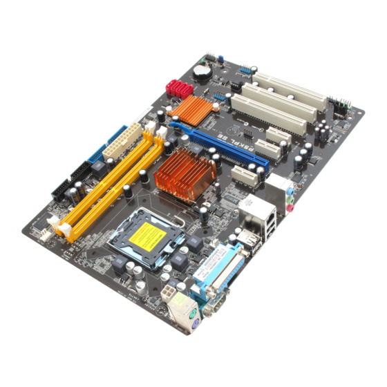
The edge with external ports goes to the rear part of the chassis as indicated in the image below. 1.5.2. Screw.holes Place six screws into the holes indicated by circles to secure the motherboard to the chassis. Do not overtighten the screws! Doing so can damage the motherboard. Place.this.side.towards. the.rear.of.the.chassis P5KPL SE ASUS P5KPL SE... -
Page 16: Motherboard Layout
20.3cm(8.0in) KBMS CPU_FAN Super ATX12V LGA775 USB34 LAN1_USB12 Intel ® G31 B0 9LPRS954A3GLF AUDIO PCIEX1_1 PCIEX16 8111C P5KPL SE PCIEX1_2 Intel ® SPEAKER ICH7 PCIEX1_3 USB56 PCI1 SATA1 SATA3 SATA2 SATA4 PCI2 Lithium Cell BIOS CMOS Power ALC662 PCI3 SB_PWR... -
Page 17: Layout Contents
Contact your retailer immediately if the PnP cap is missing, or if you see any damage to the PnP cap/socket contacts/motherboard components. ASUS will shoulder the cost of repair only if the damage is shipment/ transit-related. -
Page 18: Installing The Cpu
To install a CPU: Locate the CPU socket on the motherboard. P5KPL SE P5KPL SE CPU socket 775 Before installing the CPU, ensure that the socket box is facing towards you and the load lever is on your left. Press the load lever with your thumb Retention.tab... - Page 19 Close the load plate (A), then push the load lever (B) until it snaps into the retention tab. The motherboard supports Intel ® LGA775 processors with the Intel Enhanced Intel SpeedStep ® ® Technology (EIST) and Hyper- Threading Technology. ASUS P5KPL SE...
-
Page 20: Installing The Cpu Heatsink And Fan
Do not forget to connect CPU FAN PWM the CPU fan connector! CPU FAN IN CPU FAN PWR Hardware monitoring errors can occur if you fail to plug this connector. P5KPL SE P5KPL SE CPU fan connector 1-10 Chapter 1: Product introduction... -
Page 21: Uninstalling The Cpu Heatsink And Fan
Overview The motherboard comes with two Double Data Rate 2 (DDR2) Dual Inline Memory Modules (DIMM) sockets. The figure illustrates the location of the DDR2 DIMM sockets: P5KPL SE P5KPL SE 240-pin DDR2 DIMM sockets Channel Sockets Channel A DIMM_A1... -
Page 22: Memory Configurations
Some old-version DDR2-800 DIMMs may not match Intel On-Die-Termination (ODT) ® requirement and will automatically downgrade to run at DDR-667. If this heppens, contact your memory vendor to check to ODT value. P5KPL SE Motherboard Qualified Vendors Lists (QVL) DDR2-667MHz.capability DIMM..support. .Size Vendor... - Page 23 CENTURY 512MB Hynix HY5PS12821AFP-Y5 · · Century CENTURY 1G Hynix HY5PS12821AFP-Y5 · · Century CENTURY 1G Nanya NT5TU64M8AE-3C · · 512MB KINGBOX 512MB 667MHz KINGBOX EPD264082200-4 · · KINGBOX DDRII 1G 667MHz KINGBOX EPD264082200-4 · · ASUS P5KPL SE 1-13...
- Page 24 DDR2-800MHz.capability DIMM.support. .Size Vendor Model Brand Component 512MB Kingston KVR800D2N5/512 Samsung K4T51083QC-ZCE7 · · 512MB Kingston KVR800D2N5/512 Promos V59C1512804QBF25S0054707PEBPA · · Kingston KVR800D2N5/1G Samsung K4T51083QC-ZCE7 · · Kingston KHX6400D2LL/1G Kingston Heat-Sink Package · · Kingston KVR800D2N5/1G Nanya NT5TU64M8BE-25C62321800CP · · Kingston KHX6400D2LLK2/1GN Kingston...
- Page 25 A*: Supports one module inserted into any slot as Single-channel memory configuration. •. B*: Supports one pair of modules inserted into both the yellow slots as one pair of Dual-channel memory configuration. Visit the ASUS website for the latest DDR2-667/800/1066MHz QVL. ASUS P5KPL SE 1-15...
-
Page 26: Installing A Dimm
1.7.3. Installing.a.DIMM Unplug the power supply before adding or removing DIMMs or other system components. Failure to do so can cause severe damage to both the motherboard and the components. Unlock a DDR2 DIMM DDR2.DIMM.notch socket by pressing the retaining clips outward. -
Page 27: Expansion.slots
This motherboard supports PCI Express x1 network cards, SCSI cards and other cards that comply with the PCI Express specifications. 1.8.6. PCI.Express.x16.slot This motherboard supports a PCI Express x16 graphics card that complies with the PCI Express specifications. ASUS P5KPL SE 1-17... -
Page 28: Jumper
• Due to the chipset limitation, AC power off is required before you use the C.P.R. function. You must turn off and on the power supply or unplug and plug the power cord before rebooting the system. CLRTC P5KPL SE Normal Clear RTC (Default) P5KPL SE Clear RTC RAM 1-18 Chapter 1: Product introduction... -
Page 29: Connectors
2, 4, or 6-channel configuration. Audio 2, 4, or 6-channel configuration Port Headset.2-channel 4-channel 6-channel Light Blue Line In Rear Speaker Out Rear Speaker Out Lime Line Out Front Speaker Out Front Speaker Out Pink Mic In Mic In Bass/Center ASUS P5KPL SE 1-19... -
Page 30: Internal Connectors
P5KPL SE NOTE:Orient the red markings on the floppy ribbon cable to PIN 1. P5KPL SE Floppy disk drive connector Speaker.connector.(4-pin.SPEAKER) This 4-pin connector is for the chassis-mounted system warning speaker. The speaker allows you to hear system beeps and warnings. - Page 31 S/PDIF Out module cable to this connector, then install the module to a slot opening at the back of the system chassis. P5KPL SE SPDIF_OUT P5KPL SE Digital audio connector The S/PDIF module is purchased separately. ASUS P5KPL SE 1-21...
- Page 32 This is not a jumper! Do not place jumper cap on the fan connector! CPU_FAN CPU FAN PWM CPU FAN IN CPU FAN PWR P5KPL SE P5KPL SE CPU fan connector Only the CPU fan supports the ASUS Q-FAN feature. 1-22 Chapter 1: Product introduction...
- Page 33 The USB module cable is purchased separately. Optical.drive.audio.connector.(4-pin.CD) These connectors allow you to receive stereo audio input from sound sources such as a CD-ROM, TV tuner, or MPEG card. P5KPL SE P5KPL SE Internal audio connector ASUS P5KPL SE 1-23...
- Page 34 Legacy AC’97 pin definition compliant definition P5KPL SE Analog front panel connector • We recommend that you connect a high-definition front panel audio module to this connector to avail of the motherboard’s high-definition audio capability. • By default, this connector is set to HD Audio. If you want to connect an AC97 front panel audio module to this connector, set the Front.Panel.Support.Type item in the BIOS to...
- Page 35 • If you are uncertain about the minimum power supply requirement for your system, refer to the Recommended Power Supply Wattage Calculator at http://support.asus. com/PowerSupplyCalculator/PSCalculator.aspx?SLanguage=en-us for details. • The ATX 12 V Specification 2.0-compliant (400W) PSU has been tested to support the motherboard power requirements.
-
Page 36: System Panel Connector
PIN 1 P5KPL SE HD_LED RESET P5KPL SE System panel connector • System.power.LED.(2-pin.PWR.LED) This 2-pin connector is for the system power LED. Connect the chassis power LED cable to this connector. The system power LED lights up when you turn on the system power, and blinks when the system is in sleep mode. -
Page 37: Software.support
The following screen is used for reference only. Click.an.icon.to. display.Support.DVD/ motherboard.information Click.an.item.to.install If Autorun is NOT enabled in your computer, browse the contents of the Support DVD to locate the file ASSETUP.EXE from the BIN folder. Double-click the ASSETUP.EXE to run the DVD. ASUS P5KPL SE 1-27... - Page 38 1-28 Chapter 1: Product introduction...
-
Page 39: Chapter.2
BIOS in the future. Copy the original motherboard BIOS using the ASUS Update or AFUDOS utilities. 2.1.1. ASUS.Update.utility The ASUS Update is a utility that allows you to manage, save, and update the motherboard BIOS in Windows environment. The ASUS Update utility allows you to: ®... -
Page 40: Creating A Bootable Floppy Disk
Programs.>.ASUS.>.ASUSUpdate.>.ASUSUpdate. Select Update.BIOS from.the.Internet from the drop-down menu, then click Next. Select the ASUS FTP site nearest you to avoid network traffic, or click Auto.Select then click Next. From the FTP site, select the BIOS version that you wish to download then click Next. -
Page 41: Asus Ez Flash 2 Utility
2.1.3. ASUS.EZ.Flash.2.utility The ASUS EZ Flash 2 feature allows you to update the BIOS without having to go through the long process of booting from a floppy disk and using a DOS-based utility. The EZ Flash 2 utility is built-in the BIOS chip so it is accessible by pressing <Alt>.+.<F2> during the Power- On Self Tests (POST). -
Page 42: Afudos Utility
Updating the BIOS file To update the BIOS file using the AFUDOS utility: Visit the ASUS website (www.asus.com) and download the latest BIOS file for the motherboard. Save the BIOS file to a bootable floppy disk. We recommend that you write the BIOS filename on a piece of paper; you will need to key in the exact BIOS filename at the DOS prompt later. -
Page 43: Asus Crashfree Bios 3 Utility
2.1.5. ASUS.CrashFree.BIOS.3.utility The ASUS CrashFree BIOS 3 is an auto recovery tool that allows you to restore the BIOS file when it fails or gets corrupted during the updating process. You can update a corrupted BIOS file using the motherboard support DVD, a floppy disk or a USB flash disk that contains the updated BIOS file. - Page 44 BIOS file and starts flashing the corrupted BIOS file. Restart the system after the utility completes the updating process. • Only the USB flash disk with FAT 32/16 format and single partition can support ASUS CrashFree BIOS 3. The device size should be smaller than 8GB.
-
Page 45: Bios.setup.program
• The BIOS setup screens shown in this section are for reference purposes only, and may not exactly match what you see on your screen. • Visit the ASUS website at www.asus.com to download the latest BIOS file for this motherboard. -
Page 46: Bios Menu Screen
2.2.1. BIOS.menu.screen Menu.items Menu.bar Configuration fields General.help BIOS SETUP UTILITY Main Ai Tweaker Advanced Power Boot Tools Exit Use [ENTER], [TAB] or System Time [14:14:35] [SHIFT-TAB] to select System Date [Wed 04/16/2008] a field. Legacy Diskette A [1.44M, 3.5 in.] Use [+] or [-] to configure system Time. -
Page 47: Menu Items
A m e r i c a n Megatrends, Inc. Pop-up.window <Up>./.<Down> arrow keys or Scroll.bar <Page.Up>./<Page.Down> keys to display the other items on the screen. 2.2.9. General.help At the top right corner of the menu screen is a brief description of the selected item. ASUS P5KPL SE... -
Page 48: Main.menu
2.3. Main.menu When you enter the BIOS Setup program, the Main menu screen appears, giving you an overview of the basic system information. Refer to section 2.2.1.BIOS.menu.screen for information on the menu screen items and how to navigate through them. BIOS SETUP UTILITY Main Ai Tweaker... -
Page 49: Storage Configuration
Configuration options: [0] [5] [10] [15] [20] [25] [30] [35] 2.3.6. System.Information This menu gives you an overview of the general system specifications. The BIOS automatically detects the items in this menu. Bios.Information Displays the auto-detected BIOS information. ASUS P5KPL SE 2-11... -
Page 50: Advanced.menu
Processor Displays the auto-detected CPU specification. System.Memory Displays the auto-detected system memory. 2.4. Advanced.menu The Advanced menu items allow you to change the settings for the CPU and other system devices. Take caution when changing the settings of the Advanced menu items. Incorrect field values can cause the system to malfunction. - Page 51 Allows you to select ICH chipset voltage or set it to [Auto] for safe mode. Configuration options: [Auto] [1.5V] [1.6V] VCore.Over.Voltage.[Auto] Allows you to select VCore over voltage or set it to [Auto] for safe mode. Configuration options: [Auto] [+50mv] [+100mv] [+150mv] ASUS P5KPL SE 2-13...
-
Page 52: Usb Configuration
2.4.2 USB Configuration The items in this menu allows you to change the USB-related features. Select an item then press <Enter> to display the configuration options. The Module Version and USB Devices Enabled items show the auto-detected values. If no USB device is detected, the item shows None. USB.Functions.[Enabled] Allows you to disable or select the different values of the USB functions. -
Page 53: Chipset
Allows you to select the graphics controller as the primary boot device.Configuration options: [PCI/PEG] [PEG/PCI] PEG Port Configuration PEG Force x1 [Disabled] Allows you to enable or disable the PEG Force x1. Configuration options: [Enabled] [Disabled] ASUS P5KPL SE 2-15... -
Page 54: Onboard Devices Configuration
South Bridge Configuration Audio.Controller.[Azalia] Allows you to set the audio controller. Configuration options: [Azalia] [Disabled] Front Panel Support Type [HD Audio] Allows you to select the front panel support type. If High Definition Audio Front Panel used, please set HD Audio mode. Configuration options: [AC97] [HD Audio] 2.4.5 Onboard Devices Configuration... -
Page 55: Power.menu
[Auto] - Detected by OS. 2.5.2. ACPI.2.0.Support.[Disabled] Allows you to add more tables for Advanced Configuration and Power Interface (ACPI) 2.0 specifications. Configuration options: [Disabled] [Enabled] ASUS P5KPL SE 2-17... -
Page 56: Apm Configuration
2.5.3. ACPI.APIC.Support.[Enabled] Allows you to enable or disable the Advanced Configuration and Power Interface (ACPI) support in the Application-Specific Integrated Circuit (ASIC). When set to Enabled, the ACPI APIC table pointer is included in the RSDT pointer list. Configuration options: [Disabled] [Enabled] 2.5.4 APM Configuration... -
Page 57: Boot.menu
When set to [Disabled], BIOS performs all the POST items. Configuration options: [Disabled] [Enabled] Full.Screen.Logo.[Enabled] This allows you to enable or disable the full screen logo display feature. Configuration options: [Disabled] [Enabled] Set this item to [Enabled] to use the ASUS MyLogo2™ feature. ASUS P5KPL SE 2-19... -
Page 58: Security
Add.On.ROM.Display.Mode.[Force.BIOS] Sets the display mode for option ROM. Configuration options: [Force BIOS] [Keep Current] Bootup.Num-Lock.[On] Allows you to select the power-on state for the NumLock. Configuration options: [Off] [On] PS/2.Mouse.Support.[Auto] Allows you to enable or disable support for PS/2 mouse. Configuration options: [Disabled] [Enabled] [Auto] Wait.for.‘F1’.If.Error.[Enabled] When set to Enabled, the system waits for the F1 key to be pressed when error occurs. -
Page 59: Tools.menu
2.7.1. ASUS.EZ.Flash.2 Allows you to run ASUS EZ Flash 2. When you press <Enter>, a confirmation message appears. Use the left/right arrow key to select between [Yes] or [No], then press <Enter> to confirm your choice. Please see section 2.1.3 for details. -
Page 60: Ai Net 2
2.7.2. AI.NET.2 Check.Realtek.LAN.cable.[Disabled] Enables or disables checking of the Realtek LAN cable during the Power-On Self-Test (POST). Configuration options: [Disabled] [Enabled] 2.8. Exit.menu The Exit menu items allow you to load the optimal or failsafe default values for the BIOS items, and save or discard your changes to the BIOS items.
Need help?
Do you have a question about the P5KPL SE and is the answer not in the manual?
Questions and answers