Table of Contents
Advertisement
Advertisement
Table of Contents

Related Manuals for Asus P5KPL-AM IN


Summary of Contents for Asus P5KPL-AM IN
- Page 1 P5KPL-AM IN...
- Page 2 Product warranty or service will not be extended if: (1) the product is repaired, modified or altered, unless such repair, modification of alteration is authorized in writing by ASUS; or (2) the serial number of the product is defaced or missing.
-
Page 3: Table Of Contents
Contents Notices ......................v Safety information ..................vi About this guide ..................vi P5KPL-AM IN specifications summary ........... viii Chapter 1 Product intruction Before you proceed ..............1-1 Motherboard overview ..............1-2 1.2.1 Motherboard layout ............1-2 1.2.2 Layout contents ............... 1-2 Central Processing Unit (CPU) ........... - Page 4 Boot menu .................. 2-13 2.6.1 Boot Device Priority ............2-13 2.6.2 Boot Settings Configuration .......... 2-13 2.6.3 Security ................. 2-14 Tools menu ................. 2-15 2.7.1 ASUS EZ Flash 2 ............2-15 2.7.2 AI NET 2................ 2-15 Exit menu ..................2-16...
-
Page 5: Notices
Notices Federal Communications Commission Statement This device complies with Part 15 of the FCC Rules. Operation is subject to the following two conditions: • This device may not cause harmful interference, and • This device must accept any interference received including interference that may cause undesired operation. -
Page 6: Safety Information
Safety information Electrical safety • To prevent electric shock hazard, disconnect the power cable from the electric outlet before relocating the system. • When adding or removing devices to or from the system, ensure that the power cables for the devices are unplugged before the signal cables are connected. If possible, disconnect all power cables from the existing system before you add a device. -
Page 7: Conventions Used In This Guide
Refer to the following sources for additional information and for product and software updates. ASUS websites The ASUS website provides updated information on ASUS hardware and software products. Optional documentation Your product package may include optional documentation, such as warranty flyers, that may have been added by your dealer. -
Page 8: P5Kpl-Am In Specifications Summary
Memory Dual channel memory architecture 2 x 240-pin DIMM sockets supports unbuffered non-ECC 4GB 1066(O.C.)/800/667 MHz DDR2 memory modules * Refer to www.asus.com for memory QVL (Qualify Vendor List) Expansion Slots 1 x PCI Express x1 slot 2 x PCI slots... - Page 9 P5KPL-AM IN specifications summary Internal connectors 1 x High Definition front panel audio connector 2 x USB 2.0 connectors supports additional 4 USB ports 2 x Serial ATA connectors 1 x CPU fan connector 1 x IDE connector 1 x 24-pin EATXPWR 12 V power connector...
-
Page 10: Product Intruction
Chapter 1 Product introduction Thank you for buying an ASUS P5KPL-AM IN motherboard! ® Before you start installing the motherboard, and hardware devices on it, check the items in your motherboard package. Refer to page ix for the list of accessories. -
Page 11: Motherboard Overview
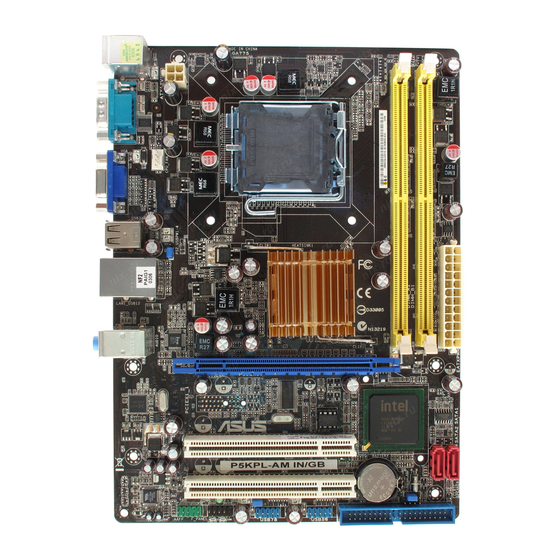
USB34 LAN1_USB12 Intel ® G31 B0 AUDIO IT8755E PCIEX1_1 8131 Intel ® BIOS ICH7 PCI1 P5KPL-AM IN Lithium Cell PCI2 CMOS Power CLRTC SPEAKER VT1705 SB_PWR USB56 USBPW5-8 PRI_IDE AAFP USB78 F_PANEL 14 13 Place six screws into the holes indicated by circles to secure the motherboard to the chassis. -
Page 12: Central Processing Unit (Cpu)
Contact your retailer immediately if the PnP cap is missing, or if you see any damage to the PnP cap/socket contacts/motherboard components. ASUS will shoulder the cost of repair only if the damage is shipment/ transit-related. - Page 13 • You may install varying memory sizes in Channel A and Channel B. The system maps the total size of the lower-sized channel for the dual-channel configuration. Any excess memory from the higher-sized channel is then mapped for single-channel operation. •...
- Page 14 Kingston KHX6400D2LL/1G 1024MB Kingston Heat-Sink Package • • Kingston KVR800D2N5/1G 1024MB Kingston D6408TR4CGL25USL3624 • • 06PECXA Kingston KVR800D2N6/1G 1024MB Elpida E5108AJBG-8E-E • • Kingston KHX6400D2K2/2G 2048MB(Kit of 2) Heat-Sink Package • • (continued on the next page) ASUS P5KPL-AM IN...
- Page 15 DIMM support Chip Vendor Part No. Size Chip NO. Brand Kingston 461625.010819 PTGC 2048MB Kingston KVR800D2N6/2G • • Kingston KHX6400D2/2G 2048MB Kingston Heat-Sink Package • • Kingston KVR800D2N5/2G 2048MB Elpida E1108ACBG-8E-E • • Kingston KVR800D2N6/4G 4096MB Elpida E2108ABSE-8G-E • • OCZ2G800R22GK 1024MB Heat-Sink Package...
-
Page 16: Expansion Slots
Visit the ASUS website at (www.asus.com) for the latest QVL. SS - Single-sided / DS - Double - sided DIMM support: • A*: Supports one module inserted into any slot as Single-channel memory configuration. • B*: Supports one pair of modules inserted into the yellow slots as one pair of Dual-channel memory configuration. -
Page 17: Clear Rtc Ram
• Due to the chipset limitation, AC power off is required before you use the C.P.R. function. You must turn off and on the power supply or unplug and plug the power cord before rebooting the system. CLRTC Normal Clear RTC P5KPL-AM IN (Default) P5KPL-AM IN Clear RTC RAM Chapter 1: Product introduction... -
Page 18: Connectors
USBPW56 jumper is for the rear USB ports. PS2_USBPW1-4 +5VSB (Default) P5KPL-AM IN P5KPL-AM IN Keyboard Power Setting Connectors 1.7.1 Rear panel ports PS/2 mouse port (green). This port is for a PS/2 mouse. LAN (RJ-45) port. Supported by Realtek 10/100 LAN controller, this port allows 10/100 connection to a Local Area Network (LAN) through a network hub. -
Page 19: Internal Connectors
RSATA_RXN2 RSATA_RXN1 RSATA_RXP2 RSATA_RXP1 P5KPL-AM IN P5KPL-AM IN SATA connectors (ICH7) right angle side Connect the right-angle side of SATA signal cable to SATA device. You may also connect the right-angle side of SATA cable to the onboard SATA port to avoid mechanical conflict with huge graphics cards. - Page 20 NOTE:Orient the red markings P5KPL-AM IN on the IDE ribbon cable to PIN 1. P5KPL-AM IN IDE connector USB connectors (10-1 pin USB56, USB78) These connectors are for USB 2.0 ports. Connect the USB module cable to any of these connectors, then install the module to a slot opening at the back of the system chassis.
- Page 21 P5KPL-AM IN pin definition compliant definition P5KPL-AM IN Analog front panel connector • We recommend that you connect a high-definition front panel audio module to this connector to avail of the motherboard’s high-definition audio capability. • If you want to connect a high-definition front panel audio module to this connector, set the Front Panel Type item in the BIOS setup to [HD Audio];...
- Page 22 +3 Volts P5KPL-AM IN PIN 1 P5KPL-AM IN ATX power connectors • For a fully configured system, we recommend that you use a power supply unit (PSU) that complies with EATX 12 V Specification 2.0 (or later version) and provides a minimum power of 400 W.
-
Page 23: System Panel Connector
PIN 1 P5KPL-AM IN HD_LED RESET P5KPL-AM IN System panel connector System power LED (2-pin PWRLED) • This 2-pin connector is for the system power LED. Connect the chassis power LED cable to this connector. The system power LED lights up when you turn on the system power, and blinks when the system is in sleep mode. -
Page 24: Software Support
Click an item to install If Autorun is NOT enabled in your computer, browse the contents of the Support DVD to locate the file ASSETUP.EXE from the BIN folder. Double-click the ASSETUP.EXE to run the DVD. 1-15 ASUS P5KPL-AM IN... -
Page 25: Chapter 2 Bios Information
BIOS in the future. Copy the original motherboard BIOS using the ASUS Update utility. 2.1.1 ASUS Update utility The ASUS Update is a utility that allows you to manage, save, and update the motherboard BIOS in Windows environment. ®... -
Page 26: Asus Ez Flash 2 Utility
2.1.2 ASUS EZ Flash 2 utility ASUS EZ Flash 2 allows you to update the BIOS without having to use a DOS-based utility. Download the latest BIOS file for this motherboard from the ASUS website at www.asus.com. To update the BIOS using EZ Flash 2. -
Page 27: Asus Crashfree Bios 3 Utility
2.1.3 ASUS CrashFree BIOS 3 utility The ASUS CrashFree BIOS 3 is an auto recovery tool that allows you to restore the BIOS file when it fails or gets corrupted during the updating process. You can update a corrupted BIOS file using the motherboard support DVD or a USB flash disk that contains the updated BIOS file. -
Page 28: Bios Setup Program
• The BIOS setup screens in this section are for reference only. They may not exactly match what you see on your screen. • Visit the ASUS website at www.asus.com to download the latest BIOS file for this motherboard. Main menu When you enter the BIOS Setup program, the Main menu screen appears, giving you an overview of the basic system information. -
Page 29: Primary Ide/Sata1-2
2.3.3 Primary IDE/SATA1-2 While entering Setup, the BIOS automatically detects the presence of IDE/SATA devices. There is a separate sub-menu for each IDE/SATA device. Select a device item then press <Enter> to display the IDE/SATA device information. The BIOS automatically detects the values opposite the dimmed items (Device, Vendor, Size, LBA Mode, Block Mode, PIO Mode, Async DMA, Ultra DMA, and SMART monitoring). -
Page 30: System Information
Manual - allows you to individually set overclocking parameters. Auto - loads the optimal settings for the system. Overclock Profile - loads overclocking profiles with optimal parameters for stability when overclocking. Test Mode - loads overclock (overclocking 5%) with spread spectrum. ASUS P5KPL-AM IN... - Page 31 The following item appears only when you set the AI Overclocking item to [Manual]. CPU Frequency [xxx] Displays the frequency sent by the clock generator to the system bus and PCI bus. The value of this item is auto-detected by the BIOS. Use the <+> and <-> keys to adjust the CPU frequency.
-
Page 32: Usb Configuration
Enable this item to boot legacy operating systems that cannot support CPUs with extended CPUID functions. Configuration options: [Disabled] [Enabled] Vanderpool Technology [Enabled] Enable this item when the processor supports Vanderpool technology. Users need to reset the computer to change the configuration of this item. Configuration options: [Disabled] [Enabled] ASUS P5KPL-AM IN... -
Page 33: Chipset
CPU TM function [Enabled] Enables or disables Intel® CPU Thermal Monitor (TM2) function, a CPU overheating protection function. When enabled, the CPU core frequency and voltage is reduced when the CPU is overheats. Configuration options: [Enabled] [Disabled] Execute Disable Bit [Enabled] Allows you to Enable/disable Execute Disable Function. -
Page 34: Onboard Devices Configuration
Palette Snooping [Disabled] When set to [Enabled], the pallete snooping feature informs the PCI devices that an ISA graphics device is installed in the system so that the latter can function correctly. Configuration options: [Disabled] [Enabled] 2-10 ASUS P5KPL-AM IN... -
Page 35: Power Menu
IRQ-xx assigned to [PCI Device] When set to [PCI Device], the specific IRQ is free for use of PCI/PnP devices. When set to [Reserved], the IRQ is reserved for legacy ISA devices. Configuration options: [PCI Device] [Reserved] Power menu The Power menu items allow you to change the settings for the Advanced Power Management (APM). -
Page 36: Hardware Monitor
VCORE Voltage, 3.3V Voltage, 5V Voltage, 12V Voltage The onboard hardware monitor automatically detects the voltage output through the onboard voltage regulators. CPU Q-Fan Control [Disabled] Allows you to enable or disable the Q-Fan control. Configuration options: [Disabled] [Enabled] 2-12 ASUS P5KPL-AM IN... -
Page 37: Boot Menu
Chassis Q-Fan Control [Disabled] Allows you to enable or disable the Q-Fan control. Configuration options: [Disabled] [Enabled] Boot menu The Boot menu items allow you to change the system boot options. Select an item then press <Enter> to display the sub-menu. BIOS SETUP UTILITY Main Advanced... -
Page 38: Security
[View Only] - allows access but does not allow change to any field. [Limited] - allows changes only to selected fields, such as Date and Time. [Full Access] - allows viewing and changing all the fields in the Setup utility. 2-14 ASUS P5KPL-AM IN... -
Page 39: Tools Menu
2.7.1 ASUS EZ Flash 2 Allows you to run ASUS EZ Flash 2. When you press <Enter>, a confirmation message appears. Use the left/right arrow key to select between [Yes] or [No], then press <Enter> to confirm your choice. Please see section 2.1.3 for details. -
Page 40: Exit Menu
When you select this option or if you press <F5>, a confirmation window appears. Select OK to load default values. Select Exit & Save Changes or make other changes before saving the values to the non-volatile RAM. 2-16 ASUS P5KPL-AM IN...
Need help?
Do you have a question about the P5KPL-AM IN and is the answer not in the manual?
Questions and answers