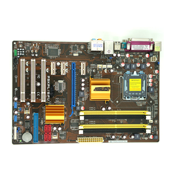
Asus P5KPL User Manual
Hide thumbs Also See for P5KPL:
Table of Contents

Advertisement

Rock Solid - Heart Touching
E 4 4 0 2
P 5 K P L / E P U
Motherboard
U s e r G u i d e

Advertisement

Table of Contents
loading

Summary of Contents for Asus P5KPL

  • Page 1 E 4 4 0 2 Rock Solid - Heart Touching P 5 K P L / E P U Motherboard U s e r G u i d e...
  • Page 2 +1-510-739-3777 +1-510-608-4555 Web site usa.asus.com Technical Support Telephone +1-812-282-2787 +1-812-284-0883 Support fax support.asus.com Online support ASUS COMPUTER GmbH (Germany and Austria) Harkort Str. 21-23, D-40880 Ratingen, Germany Address +49-2102-959911 www.asus.de Web site www.asus.de/saies Online contact Technical Support +49-1805-010923 Component Telephone...
  • Page 3 P 5 № L / E ^ U...
  • Page 4 INFORMATIONAL USE ONLY, AND ARE SUBJECT TO CHANGE AT ANY TIME WITHOUT NOTICE, AND SHOULD NOT BE C O N S T R U E D AS A COMMITMENT BY ASUS. ASUS ASSUMES NO RESPONSIBILITY OR LIABILITY FOR A N Y ERRORS OR INACCURACIES THAT MAY APPEAR IN THIS MANUAL, INCLUDING THE PRODUCTS AND SOFTWARE DESCRIBED IN IT.
  • Page 5: Table Of Contents

    Contents Notices Safety information About this guide P5KPL/EPU specifications summary Chapter 1: Product introduction Welcome! Package contents 1 -1 Special features 1.3.1 Product highlights 1.3.2 Innovative ASUS features 1 -2 Before you proceed 1 -4 Motherboard overview 1 -5 1.5.1 Placement direction 1.5.2...
  • Page 6 1.11.2 Support DVD information 1-29 Chapter 2: BIOS information Managing and updating your BIOS 2.1.1 ASUS Update utility 2.1.2 ASUS EZ Flash 2 utility 2.1.3 ASUS CrashFree BIOS 3 utility BIOS setup program 2.2.1 BIOS menu screen 2.2.2 Menu bar 2.2.3...
  • Page 7 Hardware Monitor 2-16 Boot menu 2-17 2.6.1 Boot Device Priority 2-17 2.6.2 Boot Settings Configuration 2-17 2.6.3 Security 2-18 Tools menu 2-20 2.7.1 Al NET 2 2-20 2.7.2 ASUS EZ Flash 2 2-20 2.7.3 Express Gate 2-20 Exit menu 2-21...
  • Page 8: Notices

    Complying with the REACH (Registration, Evaluation, Authorisation, and Restriction of Chemicals) regulatory framework, we published the chemical substances in our products at ASUS REACH website at http://green.asus.com/english/REACH.htm DO NOT throw the motherboard in municipal waste. This product has been designed to enable proper reuse of parts and recycling.
  • Page 9: Safety Information

    Safety information Electrical safety To prevent electrical shock hazard, disconnect the power cable from the electrical outlet before relocating the system. When adding or removing devices to or from the system, ensure that the power cables for the devices are unplugged before the signal cables are connected. If possible, disconnect all power cables from the existing system before you add a device.
  • Page 10 Refer to the following sources for additional information and for product and software updates. ASUS websites The ASUS website provides updated information on ASUS hardware and software products. Refer to the ASUS contact information. Optional documentation Your product package may include optional documentation, such as warranty flyers, that may have been added by your dealer.
  • Page 11: P5Kpl/Epu Specifications Summary

    Core™2 Duo / Celeron" E1000 and 400 Series processors Supports Intel® 45nm multi-core CPU Intel Hyper-Threading Technology ready Support Enhanced Intel SpeedStep Technology (EIST) (Refer to www.asus.com for Intel® CPU support list) Northbridge: Intel G31 Chipset Southbridge: Intel ICH7 System bus 1600(0,C.)/1333/1066/800MHZ...
  • Page 12 P5KPL/EPU specifications summary 1 x PS/2 mouse port Rear panel ports 1 x PS/2 keyboard port 1 x Optical S/PDIF Out port 1 x LAN (RJ-45) port 4 x USB 2.0/1.1 ports 8-channel audio i/O poris 1 x COM port...
  • Page 13: Chapter 1: Product Introduction

    Product introduction Welcome! Thank you for buying an ASUS" P5KPL/EPU motherboard! The motherboard delivers a host of new features and latest technologies, making it another standout in the long line of ASUS quality motherboards! Before you start installing the motherboard, and hardware devices on it, check the items in your package with the list below.
  • Page 14: Innovative Asus Features

    1.3.2 Innovative ASUS features ASUS EPU ASUS EPU detects the current computer loading and intelligently adjusts the appropriate power usage in real-time. ASUS MyLogo2™ This feature allows you to convert your favorite photo into a 256-color boot logo for a more colorful and vivid image on your screen.
  • Page 15 BIOS file using the bundled support DVD or USB disk that contains the latest BIOS file. ASUS EZ Flash 2 ASUS EZ Flash 2 is a utility that allows you to update the BIOS without using an OS-based utility. Express Gate...
  • Page 16: Before You Proceed

    Before you proceed T a k e n o t e of t h e f o l l o w i n g p r e c a u t i o n s b e f o r e y o u install m o t h e r b o a r d c o m p o n e n t s or c h a n g e a n y m o t h e r b o a r d s e t t i n g s .
  • Page 17: Motherboard Overview

    Do not overtighten the screws! Doing so can damage the motherboard. Place this side towards the rear of the chassis • • / S L S P 5 K P L / E P U • Ш m s - ® ASUS P5KPL/EPU...
  • Page 18: Motherboard Layout

    1.5.3 Motherboard layout < f f > © © © 1.5.4 Layout contents Connectors/Jumpers/Slots Page Conn»ctpn/Jumpers/Slots Page Keyboard/mouse power (3-pin PS2 USBPW1 -4) 1-21 Clear RTC RAM (3-pin CLRTC) 1-20 ATX power connectors (24-pin EATXPWR, 4-pin 1-24 System panel connector (20-8 pin PANEL) 1-27 ATX12V) CPU, chassis, and power fan connectors (4-pin...
  • Page 19: Central Processing Unit (Cpu)

    Contact your retailer immediately if the PnP cap is missing, or if you see any damage to the PnP cap/socket contacts/motherboard components. ASUS will shoulder the cost of repair only if the damage is shipment/transit-related. Keep the cap after installing the motherboard. ASUS will process Return Merchandise Authorization (RMA) requests only if the motherboard comes with the cap on the LGA775 socket.
  • Page 20 Press the load lever with your thumb (A), then move it to the left (B) until it is released from the retention tab. To prevent damage to the socket pins, do not remove the PnP cap unless you are installing a CPU. Lift the load lever in the direction of the PnP cap arrow to a 135°...
  • Page 21 DO NOT eat the Thermal Interface Material. If it gets into your eyes or touches your skin, ensure that you wash it off immediately, and seek professional medical help. To prevent contaminating the paste, DO NOT spread the paste with your finger directly. ASUS P5KPL/EPU...
  • Page 22: Installing The Cpu Heatsink And Fan

    1.6.2 Installing the CPU heatsink and fan T h e Intel® L G A 7 7 5 p r o c e s s o r r e q u i r e s a s p e c i a l l y d e s i g n e d h e a t s i n k a n d f a n a s s e m b l y to e n s u r e o p t i m u m t h e r m a l c o n d i t i o n a n d p e r f o r m a n c e .
  • Page 23: Uninstalling The Cpu Heatsink And Fan

    To uninstall the CPU heatsink and fan: Disconnect the CPU fan cable from the connector on the motherboard. Rotate each fastener counterclockwise. Pull up two fasteners at a time in a diagonal sequence to disengage the heatsink and fan assembly from the motherboard. ASUS P5KPL/EPU 1-11...
  • Page 24: System Memory

    Carefully remove the heatsink and fan assembly from the motherboard. Rotate each fastener clockwise to ensure correct orientation when reinstalling. System memory 1.7.1 Overview The motherboard comes with four Double Data Rate 2 (DDR2) Dual Inline Memory Modules (DIMM) sockets. The figure illustrates the location of the DDR2 DIMM sockets: P 5 K P L / E P U 2 4 0 - p i n D D R 2 D I M M s o c k e t s 1-24 Chapter 1: Product introduction...
  • Page 25: Memory Configurations

    ODT value. • Due to chipset limitation, DDR2-800 with CL=4 will be downgraded to run at DDR2-667 by default setting. If you want to operate with lower latency, adjust the memory timing manually. ASUS P5KPL/EPU 1-13...
  • Page 26 P5KPL7EPU Motherboard Qualified Vendors Lists (QVL) DDR2-667 MHz capability D W M support s s / V t a d o r Size Chip Brand Chip N o , "Timing Part No. Ш № Ш : _ | A-Data M20AD5G314170Q1C58 1024MB ADATA AD2 9608A8A-3EG80814...
  • Page 27 DDR2-1066 MHz capability DIMM support Chip Vendor Part No. Size Chip NO. "Timing • Я Brand в - Crucial BLl 2P64AA1065.8FE5(epp) 2GP{2 X 1GB) Heat-Sink Package GB22GB8500C5DC 1024MB GEIL GEIL GL2L128M88BA25AB GB24GB8500C5QC 1024MB GEIL GEIL GL2L1L.m8BA25AB GB24GB8500C5DC 2048MB GEIL GL2L128M88BA25AB GEIL Kingston KHX8500D2/ 512...
  • Page 28: Installing A Dimm

    1.7.3 Installing a DIMM Unplug the power supply before adding or removing DIMMs or other system components. Failure to do so can cause severe damage to both the motherboard and the components. install a D I M M : P r e s s t h e r e t a i n i n g clips o u t w a r d t o u n l o c k a D D R 2 D I M M s o c k e t .
  • Page 29: Expansion Slots

    This motherboard supports PCI Express x1 network cards, SCSI cards, and other cards that comply with the PCI Express specifications. 1.8.5 PCI Express x16 slot This motherboard supports a PCI Express x16 graphics card that complies with the PCI Express specifications. ASUS P5KPL/EPU 1-17...
  • Page 30: Jumpers

    Jumpers Clear RTC R A M (3-pin CLRTC) This jumper allows you to clear the Real Time Clock (RTC) RAM in CMOS. You can clear the C M O S memory of date, time, and system setup parameters by erasing the C M O S RTC RAM data.
  • Page 31 U S B P W 5 - 8 B E ] 0ES +5VSB (Default) P 5 K P L / E P U U S B D e v i c e W a k e U p ASUS P5KPL/EPU 1-19...
  • Page 32: Connectors

    1.10 Connectors Rear panel connectors 1.10.1 PS/2 mouse port (green). This port is for a PS/2 mouse. Parallel port. This 25-pin port connects a parallel printer, a scanner, or other devices. LAN (RJ-45) port. This port allows Gigabit connection to a Local Area Network (LAN) through a network hub.
  • Page 33: Internal Connectors

    P 5 K P L / E P U f a n c o n n e c t o r s Only the C P U fan supports the A S U S Q - F A N feature. ASUS P5KPL/EPU 1-21...
  • Page 34 A T X p o w e r c o n n e c t o r s ( 2 4 - p i n E A T X P W R , 4 - p i n A T X 1 2 V ) T h e s e c o n n e c t o r s a r e for A T X p o w e r s u p p l y p l u g s .
  • Page 35 The signal is then generated as a chassis intrusion event. By default, the pin labeled "Chassis Signal" and "Ground" are shorted with a jumper cap. Remove the jumper caps only when you intend to use the chassis intrusion detection feature. 1-23 ASUS P5KPL/EPU...
  • Page 36 IDE connector (40-1 pin P R L E I D E ) The onboard IDE connector is for the Ultra DMA 100/66 signal cable. There are three connectors on each Ultra DMA 100/66 signal cable: blue, black, and gray. Connect the blue connector to the motherboard's IDE connector, then select one of the following modes to configure your device.
  • Page 37 Pressing the power switch for more than four seconds while the system is O N turns the system OFF. Reset button (2-pin RESET) This 2-pin connector is for the chassis-mounted reset button for system reboot without turning off the system power. ASUS P5KPL/EPU 1-25...
  • Page 38 Never connect a 1394 cable to the USB connectors. Doing so will damage the motherboard! You can connect the front panel USB cable to the ASUS Q-Connector (USB, blue) first, and then install the Q-Connector (USB) to the USB connector onboard if your chassis supports front panel USB ports.
  • Page 39 CD-ROM, TV tuner, or MPEG card. P 5 K P L / E P U I n t e r n a l a u d i o c o n n e c t o r 1-27 ASUS P5KPL/EPU...
  • Page 40 F r o n t p a n e l a u d i o c o n n e c t o r ( 1 0 - 1 pin A A F P ) T h i s c o n n e c t o r is for a c h a s s i s - m o u n t e d f r o n t p a n e l a u d i o I/O m o d u l e t h a t s u p p o r t s either H D A u d i o or l e g a c y A C ' 9 7 a u d i o s t a n d a r d .
  • Page 41: Software Support

    Click an item to install If Autorun is NOT enabled in your computer, browse the contents of the Support DVD to locate the file ASSETUP.EXE from the BIN folder. Double-click the ASSETUP.EXE to run the DVD. ASUS P5KPL/EPU 1-29...
  • Page 42: Chapter 2: Bios Information

    Update. 2.1.1 ASUS Update utility The ASUS Update is a utility that allows you to manage, save, and update the motherboard BIOS in Windows' environment. • ASUS Update requires an Internet connection either through a network or an Internet Service Provider (ISP).
  • Page 43: Asus Ez Flash 2 Utility

    The A S U S EZ Flash 2 feature allows you to update the BIOS without using an OS-based utility. Before you start using this utility, download the latest BIOS file from the ASUS website at www.asus.com. To update the BIOS using EZ Flash 2:...
  • Page 44: Asus Crashfree Bios 3 Utility

    W h e n the correct BIOS file is found, EZ Flash 2 performs the BIOS update process and automatically reboots the system when done. • Only a USB flash disk with FAT 32/16 format and single partition can support the ASUS EZ Flash 2 utility. •...
  • Page 45: Bios Setup Program

    Restart the system after the utility completes the updating process. Only a USB flash disk with FAT 32/16 format and single partition can support ASUS CrashFree BIOS 3. The device size should be smaller than 8GB. DO NOT shut down or reset the system while updating the BIOS! Doing so can cause system boot failure! The recovered BIOS may not be the latest BIOS version for this motherboard.
  • Page 46: Bios Menu Screen

    The BIOS setup screens shown in this section are for reference purposes only, and may not exactly match what you see on your screen. Visit the ASUS website at www.asus.com to download the latest BIOS file for this motherboard. 2.2.1...
  • Page 47: Navigation Keys

    2.2.3 Navigation keys At the bottom right corner of a menu screen are the navigation keys for that particular menu. Use the navigation keys to select items in the menu and change the settings. tj/'' Some of the navigation keys differ from one screen to another. 2.2.4 Menu items The highlighted item on the menu bar displays the specific items for that menu.
  • Page 48: Main Menu

    R O M drive. Select [ARMD] (ATAPI Removable Media Device) if your device is either a ZIP, LS-120, or MO drive. Configuration options: [Not Installed] [Auto] [CDROM] [ARMD] К " " " This item does appear when you select the SATA 1/2/3/4 devices. ASUS P5KPL/EPU 49...
  • Page 49: Ide Configuration

    LBA/Large Mode [Auto] Enables or disables the LBA mode. Setting to [ A u t o ] enables the LBA mode if the device supports this mode, and if the device was not previously formatted with LBA mode disabled. Configuration options: [Disabled] [Auto] Block (Multi-sector Transfer) M [Auto] Enables or disables data multi-sectors transfers.
  • Page 50: System Information

    Select either one of the preset overclocking configuration options: M a n u a l - allows you to individually set overclocking parameters. Auto - loads the optimal settings for the system. Overclock Profile - loads overclocking profiles with optimal parameters for stability when overclocking. ASUS P5KPL/EPU...
  • Page 51 T h e following item appears only w h e n y o u set t h e A I O v e r c l o c k i n g item to [ M a n u a l ] , CPU Frequency [xxxi Displays the frequency sent by the clock generator to the system bus and PCI bus.
  • Page 52: Usb Configuration

    USB support is disabled. Configuration options: [Disabled] [Enabled] [Auto] USB 2.0 Controller Mode [HiSpeed] Allows you to configure the USB 2.0 controller in HiSpeed (480Mbps) or Full Speed (12Mbps). Configuration options: [FullSpeed] [HiSpeed] ASUS P5KPL/EPU 1-11...
  • Page 53: Cpu Configuration

    The following item may only appear when a USB storage device is plugged. USB Mass Stroage Device Configuration USB Mass Stroage Reset Delay [20 Sec] Allows you to set the USB mass stroage reset delay. Configuration options: [10 Sec] [20 Sec] [30 Sec] [ 40 Sec] Emulation Type [Auto] Allows you to set the emulation type.
  • Page 54: Chipset

    Allows you to enable or disable the boot ROM in the onboard LAN controller. This item appears only when the Onboard LAN item is set to Enabled. Configuration options: [Disabled] [Enabled] Serial Portl Address [3F8/IRQ4] Allows you to select the Serial Portl base address. Configuration options: [Disabled] [3F8/IRQ4] [2F8/IRQ3] [3E8/1RQ4] [2E8/IRQ3] ASUS P5KPL/EPU 1-13...
  • Page 55: Pcipnp

    Parallel Port Address [378] Allows you to select the Parallel Port base addresses. Configuration options: [Disabled] [378] [278] [3BC] Parallel Port Mode [ECP] Allows you to select the Parallel Port mode. Configuration options: [Normal] [Bi-Directional] [EPP] [ECP] ECP Mode DMA Channel [DMA3] Appears only when the Parallel Port Mode is set to [ЕСР].
  • Page 56: Power Menu

    [Power On], the system goes on after an AC power loss. When set to [Last State], the system goes into either off or on state, whatever the system state was before the AC power loss. Configuration options: [Power Off] [Power On] [Last State] ASUS P5KPL/EPU 1-15...
  • Page 57: Hardware Monitor

    Resume On Ring [Disabled] Allows you to enable or disable Rl to generate a wake event. Configuration options: [Disabled] [Enabled] Resume On PCI Devices [Disabled] When set to [Enabled], this parameter allows you to wake the system through a PCI LAN or modem card.
  • Page 58: Boot Menu

    POST items. Configuration options: [Disabled] [Enabled] Full Screen Logo [Enabled] This allows you to enable or disable the full screen logo display feature. Configuration options: [Disabled] [Enabled] Set this item to [Enabled] to use the ASUS MyLogo2™ feature. ASUS P5KPL/EPU 1-17...
  • Page 59: Security

    AddOn ROM Display Mode [Force BIOS] Sets the display m o d e for option ROM. Configuration options: [Force BIOS] [Keep Current] Bootup Num-Lock [On] Allows you to select the power-on state for the NumLock. Configuration options: [Off] [On] PS/2 Mouse Support [Auto] Allows you to enable or disable support for PS/2 mouse.
  • Page 60 W h e n set to [Setup], BIOS checks for user password when accessing the Setup utility. When set to [ A l w a y s ] , BIOS checks for user password both when accessing Setup and booting the system. Configuration options: [Setup] [Always] ASUS P5KPL/EPU 1-19...
  • Page 61: Tools Menu

    Please see section 2.1.3 for details. 2.7.3 Express Gate [Enabled] Allows you to enable or disable the ASUS Express Gate feature. The ASUS Express Gate feature is a unique instant-on environment that provides quick access to the Internet browser and Skype. Configuration options: [Enabled] [Disabled]...
  • Page 62: Exit Menu

    When you select this option or if you press <F5>, a confirmation window appears. Select O K to load default values. Select Exit & Save Changes or make other changes before saving the values to the non-volatile RAM. ASUS P5KPL/EPU 1-21...
  • Page 63 w w w . a s u s . c o m 671824...
  • Page 64 Wyłącz systemi włącz go ponownie, a następnie naciśnij <Delete> podczas testu POST W celu aktualizacji BIOS poprzez ASUS EZ Flash 2: Uruchom ponownie system i naciśnij press <Alt> + <F2> podczas testu POST w celu uruchomienia EZ Flash 2. Włóż dysk flash USB z najnowszym plikiem BIOS.
  • Page 65 • Płyta główna nie obsługuje pamięci DIMM o pojemności 256 megabitów (MB) lub mniejszej. Tylko żółte gniazdo może obsługiwać pamięć ОС 1066 MHz. • W przypadku instalowania czterech modułów DDR2 DIMM należy zamontować tylko moduły jednostronne pamięci. ASUS P5KPL/EPU 84...
  • Page 66 Rozmieszczenie elementów płyty głównej Instalacja procesora Aby zainstalować procesor: Naciśnij kciukiem (A) dźwignię ładowania, a następnie przesuń ją w lewo (B), aż do jej zwolnienia z zatrzasku mocującego. Pokrywka PnP ASUS P5KPL/EPU 20...
  • Page 67 Ihe servirao de guia. Se se deparar com problemas ao m'vel do sistema, ou se o sistema ficar instavel após alteraęao das definięoes, carregue as predefinięóes de configuraęao. Visite o web site da ASUS (www.asus.com) para obter as actualizaęoes.
  • Page 68 U4402 P5KPL/EPU Motherboard Q u i c k S t a r t ©ш<$<е Franęais Deutsh Italiano Espańol Русский Portugues Polski Ćesky Magyar Български Romana Srpski First Edition April 2009 Copyright © 2009 ASUSTeK COMPUTER INC. All Rights Reserved...

This manual is also suitable for:

EpuP5epu

Table of Contents