
Subscribe to Our Youtube Channel
Related Manuals for Victor PAK 200i


Summary of Contents for Victor PAK 200i
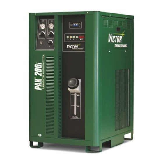
- Page 1 380V 400V 480V 200i ® PLASMA CUTTING SYSTEM Operating Manual Revision: AB Issue Date: July 1, 2015 Manual No.: 0-5335 VictorThermalDynamics.com...
- Page 2 WE APPRECIATE YOUR BUSINESS! Congratulations on your new Victor Thermal Dynamics product. We are proud to have you as our customer and will strive to provide you with the best service and reliability in the industry. This product is backed by our extensive warranty and world-wide service network. To locate your nearest distribu- tor or service agency call 1-800-752-7622, or visit us on the web at www.thermal-dynamics.com.
- Page 3 WARNING Read and understand this entire Manual and your employer’s safety practices before installing, operating, or servicing the equipment. While the information contained in this Manual represents the Manufacturer’s best judgement, the Manufacturer assumes no liability for its use. Plasma Cutting Power Supply, Pak 200i ®...
- Page 4 Be sure this information reaches the operator. You can get extra copies through your supplier. CAUTION These INSTRUCTIONS are for experienced operators. If you are not fully familiar with the principles of operation and safe practices for arc welding and cutting equipment, we urge you to read our booklet, “Precautions and Safe Practices for Arc Welding, Cutting, and Gouging,”...
- Page 5 ASSUREZ-VOUS QUE CETTE INFORMATION EST DISTRIBUÉE À L’OPÉRATEUR. VOUS POUVEZ OBTENIR DES COPIES SUPPLÉMENTAIRES CHEZ VOTRE FOURNISSEUR. ATTENTION Les INSTRUCTIONS suivantes sont destinées aux opérateurs qualifiés seulement. Si vous n’avez pas une connaissance approfondie des principes de fonctionnement et des règles de sécurité pour le soudage à l’arc et l’équipement de coupage, nous vous suggérons de lire notre brochure «...
- Page 6 This Page Intentionally Blank...
-
Page 7: Table Of Contents
TABLE OF CONTENTS SECTION 1: SAFETY .......................1-1 1.01 Safety Precautions - ENGLISH ..............1-1 1.02 Précautions de sécurité - FRENCH CANADIAN ........1-6 SECTION 2: SPECIFICATIONS ....................2-1 2.01 General Description Of The System ............2-1 2.02 Plasma Power Supply .................2-1 2.03 Plasma Cutting Torch ..................2-1 2.04 System Component Layout .................2-1 2.05... - Page 8 TABLE OF CONTENTS SECTION 6: REPLACEMENT ASSEMBLIES & PARTS ............6-1 6.01 Replacement Power Supply ................6-1 6.02 Leads and Cables ..................6-2 6.03 Power Supply External Replacement Parts ..........6-3 6.04 Power Supply Replacement Parts - Lower Right Side ........6-4 6.05 Power Supply Replacement Parts - Upper Right Side ........6-5 6.06 Power Supply Replacement Parts - Lower Left Side .........6-6 6.07...
- Page 9 TABLE OF CONTENTS APPENDIX 14: GAS BOX LAYOUT ..................A-25 APPENDIX 15: COOLING DIAGRAM .................. A-26 APPENDIX 16: SYSTEM SCHEMATICS ................A-28 System Schematic 380V - 415VAC - pg1 .............. A-28 System Schematic 380V - 415VAC - pg2 .............. A-30 System Schematic 400V CE - pg1 ................
- Page 10 TABLE OF CONTENTS This Page Intentionally Blank...
-
Page 11: Section 1: Safety
PAK 200i SECTION 1: SAFETY 1.01 Safety Precautions - ENGLISH WARNING: These Safety Precautions are for your protection. They summarize precautionary information from the references listed in Additional Safety Information section. Before performing any installation or operating procedures, be sure to read and follow the safety precautions listed below as well as all other manuals, material safety data sheets, labels, etc. - Page 12 PAK 200i ELECTRICAL SHOCK -- Contact with live electrical parts and ground can cause severe injury or death. DO NOT use AC welding current in damp areas, if movement is confined, or if there is danger of falling. 1. Be sure the power source frame (chassis) is connected to the ground system of the input power.
- Page 13 PAK 200i CYLINDER HANDLING -- Cylinders, if mishandled, can rupture and violently release gas. Sudden rupture of cylinder, valve, or relief device can injure or kill. Therefore: 1. Use the proper gas for the process and use the proper pressure reducing regulator designed to operate from the compressed gas cylinder.
- Page 14 PAK 200i Meaning of symbols - As used throughout this manual: Means Attention! Be Alert! Your safety is involved. Means immediate hazards which, if not avoided, will result in immediate, serious per- DANGER sonal injury or loss of life. CAUTION Means potential hazards which could result in personal injury or loss of life.
- Page 15 PAK 200i This Page Intentionally Blank Manual 0-5335 SAFETY INSTRUCTIONS...
-
Page 16: Précautions De Sécurité - French Canadian
PAK 200i 1.02 Précautions de sécurité - FRENCH CANADIAN AVERTISSEMENT : Ces règles de sécurité ont pour but d’assurer votre protection. Ils récapitulent les informations de précaution provenant des références dans la section des Informations de sécurité sup- plémentaires. Avant de procéder à l’installation ou d’utiliser l’unité, assurez-vous de lire et de suivre les précautions de sécurité... - Page 17 PAK 200i 5. Assurez-vous de ne pas excéder la capacité de l’équipement. Par exemple, un câble de soudage surchargé peut surchauffer et provoquer un incendie. 6. Une fois les opérations terminées, inspectez l’aire de travail pour assurer qu’aucune étincelle ou projec- tion de métal incandescent ne risque de provoquer un incendie ultérieurement.
- Page 18 PAK 200i LES VAPEURS ET LES GAZ -- peuvent causer un malaise ou des dommages corporels, plus particu- lièrement dans les espaces restreints. Ne respirez pas les vapeurs et les gaz. Le gaz de protection risque de causer l’asphyxie. Par conséquent : 1.
- Page 19 PAK 200i 4. N’utilisez pas l’équipement de façon abusive. Gardez l’équipement à l’écart de toute source de chaleur, notamment des fours, de l’humidité, des flaques d’eau, de l’huile ou de la graisse, des atmosphères corrosives et des intempéries. 5. Laissez en place tous les dispositifs de sécurité et tous les panneaux de la console et maintenez-les en bon état.
- Page 20 PAK 200i MISE EN GARDE L’équipement pourrait basculer s’il est placé sur une surface dont la pente dépasse 15°. Vous pourriez vous blesser ou endommager l’équipement de façon importante. 15° Art# A-12726 MISE EN GARDE Soulevez à l’aide de la méthode et des points d’attache illustrés afin d’éviter de vous blesser ou d’endommager...
-
Page 21: Section 2: Specifications
PAK 200i SECTION 2: SPECIFICATIONS 2.01 General Description Of The System A typical PAK 200i plasma cutting system includes: • One Power Supply • General Purpose Plasma Cutting Torch with Connecting Leads • Torch Spare Parts Kit The components are connected at installation. -
Page 22: Power Supply Specifications & Electrical Requirements
PAK 200i 2.05 Power Supply Specifications & Electrical Requirements PAK 200i 380V Power Supply Specifications Max OCV (U0) 400 vdc Max Output Current 200 Amps Output Voltage 60 - 160 vdc Duty Cycle Rating 100% @ 200A @ 200V (40 kW) Operating range 14°F to 122°F (-10°C to + 50°C) -
Page 23: Power Supply Dimensions
PAK 200i 2.06 Power Supply Dimensions 47.77 inch 1213 mm 35.97 inch 914 mm 490 lb / 222 kg 27.6 inch 701 mm Art # A-11460_AB Manual 0-5335 SPECIFICATIONS... -
Page 24: Power Supply Rear Panel Features
PAK 200i 2.07 Power Supply Rear Panel Features Customer Circuit Breakers Optional Ports Plasma Gas Port USER INPUT Shield Gas Port HEIGHT CONTROL To Torch AIR / O / H35 J15 - CNC PLASMA PLASMA CB2 - 5A 120 VAC... - Page 25 PAK 200i Customer Circuit Breakers Optional Ports Plasma Gas Port USER INPUT Shield Gas Port HEIGHT CONTROL To Torch AIR / O / H35 J15 - CNC PLASMA PLASMA CB2 - 5A 120 VAC CB3 - 5A 24 VAC Torch Leads Port...
-
Page 26: Gas Requirements
Gas Console. Specify Dual Stage Stainless diaphragm regulators for hi-pressure cylinders (> 400 inlet psi) (example: Victor VTS-450-D-500,) Single stage Station-stainless diaphragm regulator for low pressure (< 350 inlet psi) liquid or bulk tank supply ap- plication (example Victor # LC-350DR). -
Page 27: Pch/M 200 Torch Specifications
PAK 200i 2.09 PCH/M 200 Torch Specifications A. Torch Dimensions (35.6mm) 1.4 in. 70° 3.3 in. (83.8mm) 1.5 in. 13.3 in. (38.1mm) (337mm) 13.5 in. (342.9mm) 3.5 in. (88.9mm) 1.4 in. (35.6mm) 90° 1.5 in. (38.1mm) 17.4 in. (44.2mm) 4.3 in. - Page 28 PAK 200i This Page Intentionally Blank SPECIFICATIONS Manual 0-5335...
-
Page 29: Section 3: Installation
SECTION 3: INSTALLATION 3.01 Installation Requirements Electric Supply The electrical supply network, the gas and water supply system must meet local safety standards. This conformity must be checked by qualified personnel. PAK 200i Power Supply Input Suggested Sizes (See Note) Power Current... -
Page 30: Cables And Leads Identification
PAK 200i 3.02 Cables and Leads Identification Refer to section 3.05 and 3.06 for ground connections and ground cables. G: Torch Lead Set, Shielded Torch - Coolant Supply w/Negative Control/ - Coolant Return Pendant - Control Cable PAK 200i - Plasma Gas w/Pilot Return... -
Page 31: Position The Power Supply
PAK 200i 3.04 Position the Power Supply WARNING Do not touch live electrical parts. Disconnect input power conductors from de-energized supply line before moving unit. FALLING EQUIPMENT can cause serious personal injury and equipment damage. Use the lifting eye when using straps to lift the power supply. -
Page 32: Primary Power Connections
PAK 200i 3.05 Primary Power Connections The primary power cable and through hole cable grip must be supplied by the end user and connected to the power supply. Refer to local and national electrical codes for suggested cable and fuse sizes. - Page 33 PAK 200i Connect Input Power and System Ground Cables for 400V CE systems 1. Remove the input power cover to the right of the coolant filter at the rear of the power supply. To do this remove the two screws then lift up and pull away.
-
Page 34: Connect Work Cable
PAK 200i 3.06 Connect Work Cable 1. Refer to the illustration below. Pass the end of the work cable through the cord grip at the back of the power supply rear panel, then through the bottom opening in the bulkhead panel. -
Page 35: Connect Gas Supply Lines
PAK 200i 3.07 Connect Gas Supply Lines 1. Connect the gas supply lines to the appropriate input ports shown below. The first view shows factory default for using shop air. All other gasses to use the second view, bypassing the two stage air filter. -
Page 36: Auxiliary Connections
PAK 200i 3.08 Auxiliary Connections The terminal strip has Arc Volts (-) connection to power supply negative output TORCH terminal, Arc Volts (+) connection to power supply positive output WORK terminal. These are for a height control that requires connection to the full non-divided arc voltage. Also available on the terminal strip are 120VAC and 24 VAC. - Page 37 PAK 200i Torch Leads: Coolant Supply & Return Plasma Gas Shield Gas Art # A-12376 Coolant Supply Connection (Tagged Green) Plasma Gas /Pilot Return Connection Shield Gas Connection Coolant Return Connection (Tagged Red) Art # A-12377 Torch Leads Re-install the side cover(s) cover.
-
Page 38: Torch Parts Selection
PAK 200i 3.10 Torch Parts Selection Depending on the type of operation to be done (standoff cutting, drag cutting or gouging) determines the torch parts to be used. Torch parts: Shield Cup, Cutting Tip, Electrode, Gas Distributor, and Cooling Tube (Cooling Tube for Gouging Only). - Page 39 PAK 200i 1. Unscrew and remove the shield cup from the Torch Head. 2. Using the multi-purpose wrench (5/8 inch slot) remove the tip. 3. Tilt the Torch Head to remove the gas distributor. The end of the multi-purpose wrench can be used to help remove the gas distributor.
-
Page 40: 3:11 Fill Cooling System
* For mixing with D-I Cool 7-3583 1. Fill the coolant tank to the level shown, with Victor Thermal Dynamics coolant. The coolant level is visible through the translucent coolant tank. The amount of coolant required varies with torch leads length. - Page 41 PAK 200i 3. After the complete system has been installed, check that the coolant has been pumped through the system as follows (see NOTE): NOTE! The system will most likely require more coolant after turning the system ON for the first time.
- Page 42 PAK 200i This Page Intentionally Blank 3-1� INSTALLATION Manual 0-5335...
-
Page 43: Section 4: Operation
PAK 200i SECTION 4: OPERATION 4.01 Power Supply Indicators AC Indicator Gas Indicator Status Indicator Temp Indicator DC Indicator Art # A-11467 AC Power Lamp Indicates unit has passed the input power tests and AC power is being supplied to the inverter modules via the input contactor when the ON/OFF switch is in ON position. -
Page 44: Control Console Features
PAK 200i 4.02 Control Console Features Standard System PLASMA SHIELD Art # A-11468 Shield Gas Plasma Gas Pressure Gauge Pressure Gauge PLASMA SHIELD Plasma Gas Pressure Shield Gas Pressure Control Knob Control Knob Amperage / Run / Set Selector Current Selector Run / Set Selector: Use SET position to adjust plasma and shield pressures and flows. -
Page 45: Operating Set-Up
PAK 200i 4.03 Operating Set-up Follow this set-up procedure each time the system is operated: WARNING Disconnect primary power at the source before assembling or disassembling power supply, torch parts, torch and leads assemblies or adding coolant. A. Coolant Level Inspection Check the coolant level in the coolant tank at the front of the unit. -
Page 46: System Operation
PAK 200i 3. To set the Shield Gas pressure: For Gas Shield: a. Pull out the Shield Gas Pressure Control Knob. b. Turn the knob to adjust gas pressure. c. Push the knob back in to lock the pressure setting. - Page 47 Return RUN/SET switch to RUN mode. Attempting to START while in the SET mode will cause fault L303, normally indicating low gas pressure but in PAK 200i units also indicates trying to START while in SET. 4. Set cutting current.
-
Page 48: Gas Selection
PAK 200i WARNING AC power is still present inside the unit. • Fans and pump as well as all indicators turn off. • The display may show a fault code for a moment, this is a normal part of shutting off power and does not indicate a fault. -
Page 49: Power Supply Status Codes
PAK 200i 4.06 Power Supply Status Codes NOTE! See the Appendix for Advanced Troubleshooting On start-up and during operation, the power supply control circuitry performs various tests. If the circuitry detects a condition requiring operator attention, the status display on the front panel shows a 3 digit code preceded by either letter “E”... - Page 50 PAK 200i CCM Status Code Group 2 -- Plasma Power Supply Code Message Remedy / Comments Blown wall fuse, Blown unit fuse F1 or F2 or rear panel, Bad power cable connection; Defec- Missing AC Phase tive System Bias PCB.
- Page 51 PAK 200i Code Message Remedy / Comments Inverter 2A Incom- Unsupported Inverter Revision; Ribbon cable CCM J33 to Inverter Module 2 Section A dam- patible Revision aged; CCM code version incompatible with Inverter revision or model Not used Reserved for other models with additional inverter sections.
- Page 52 PAK 200i Code Message Remedy / Comments Inverter 2A Circuit Inverter Module 2 Section A detected a circuit fault; Damaged Inverter Module 2 Fault Not used Reserved for other models with additional inverter sections. Not used Reserved for other models with additional inverter sections.
- Page 53 Reserved for other models. Reserved No information available; Contact customer service Gas Supply Pressure PAK 200i is in SET mode or Plasma gas pressure is too low; Defective gas pressure out of range. sensor (PS1). Gas Control Purging Normal following power up or returning from Plasma Disable.
- Page 54 PAK 200i CCM Status Code Group 6 -- CCM Code Message Remedy / Comments Analog Voltage Error Defective CCM, replace. ADC or DAC error Defective CCM, replace. Reserved No information available; Contact customer service Data Memory error Defective CCM, replace.
-
Page 55: Cut Quality
PAK 200i 4.07 Cut Quality Cut quality requirements differ depending on application. For instance, nitride build-up and bevel angle may be major factors when the surface will be welded after cutting. Dross-free cutting is important when finish cut quality is desired to avoid a secondary cleaning operation. Cut quality will vary on different materials and thicknesses. -
Page 56: Recommended Cutting Speeds
PAK 200i Direction of Cut The plasma gas stream swirls as it leaves the torch to maintain a smooth column of gas. This swirl effect results in one side of a cut being more square than the other. Viewed along the direction of travel, the right side of the cut is more square than the left. - Page 57 PAK 200i Type Torch: PCH-200 Type Material: Stainless Steel Type Plasma Gas: Air Type Secondary Gas: Air Output Speed Plasma Gas Sec Gas Thickness Volts (Per Minute) Standoff Press Press Total Flow (SCFH) Pierce Height Amperage Inches mm (Cat. No.)
- Page 58 PAK 200i Type Torch: PCH-200 Type Material: Mild Steel Type Plasma Gas: Air Type Secondary Gas: Air Output Speed Plasma Gas Thickness Volts (Per Minute) Standoff Press Sec Gas Press Total Flow (SCFH) Pierce Height Amperage Inches mm (Cat. No.)
- Page 59 PAK 200i Type Torch: PCH-200 Type Material: Stainless Steel Type Plasma Gas: Ar-35H2 Type Secondary Gas: Nitrogen Output Speed Plasma Gas Thickness Volts (Per Minute) Standoff Press Sec Gas Press Total Flow (SCFH) Pierce Height Amperage Inches mm (Cat. No.)
- Page 60 PAK 200i This Page Intentionally Blank 4-18 OPERATION Manual 0-5335...
-
Page 61: Section 5: Maintenance
PAK 200i SECTION 5: MAINTENANCE 5.01 General Maintenance Perform the following checks periodically to ensure proper system performance. Power Supply Maintenance Schedule Daily Check coolant level; add coolant as needed. Check gas hose connections and pressures. Check cooling fan; clean as needed. -
Page 62: Coolant Replacement Procedure
PAK 200i 5.03 Coolant Replacement Procedure Replace coolant as follows: 1. Disconnect the system from main input power. 2. Remove the lower right side panel. 3. Locate the coupling in the coolant line that comes from the bottom of the coolant tank, #1 in the following illustration. -
Page 63: Arc Starter Service
PAK 200i 5.04 Arc Starter Service Arc Starter Service Chart Symptom Cause Check Remedy Flush system, Coolant has become conductive Use conductivity meter replace coolant. Spark gap set too close Check with feeler gauge Set to 0.020” ±0.002” High Frequency cap (C4) Use capacitance meter Reconnect or replace. -
Page 64: Arc Starter Spark Gap Adjustment
PAK 200i 5.05 Arc Starter Spark Gap Adjustment 1. Shut off input power. Remove the top console cover. 2. Adjust the spark gap as shown. Re-install the top cover. 0.020" ± 0.002" 0.51 ± 0.05 mm Art # A-12868 5-�... -
Page 65: Section 6: Replacement Assemblies & Parts
Complete Unit / Component Catalog# PAK 200i Power Supply, 208/230 3-2233 PAK 200i Power Supply, 480V 3-2239 PAK 200i Power Supply, 380V CCC 3-2245 PAK 200i Power Supply, 400V CE 3-2251 PAK 200i Power Supply, 600V 3-2257 Complete Torch and Leads (Hand Torch) Catalog# Lead Assembly, PCH200 70°, 25’... -
Page 66: Leads And Cables
PAK 200i 6.02 Leads and Cables G: Torch Lead Set, Shielded Torch - Coolant Supply w/Negative Control/ - Coolant Return Pendant - Control Cable PAK 200i - Plasma Gas w/Pilot Return Power Supply - Shield Gas Primary power Torch Ground... -
Page 67: Power Supply External Replacement Parts
PAK 200i 6.03 Power Supply External Replacement Parts Item # Description Catalog # Power Supply Top Panel 9-7300 Power Supply Upper Right and Left Side 9-7301 Power Supply Lower Right Side 9-7302 Power Supply Lower Left Side 9-7304 Input Power Cover... -
Page 68: Power Supply Replacement Parts - Lower Right Side
PAK 200i 6.04 Power Supply Replacement Parts - Lower Right Side Item # Description Ref. Des. Catalog # Coolant Tank, Cap 8-5124 Coolant Tank 9-7305 Sensor, Coolant level 9-7307 Pump, Coolant, Assembly (with motor) 9-7309 Pump, Coolant, Assembly (no motor) -
Page 69: Power Supply Replacement Parts - Upper Right Side
PAK 200i 6.05 Power Supply Replacement Parts - Upper Right Side Item # Description Ref. Des. Catalog # Pump Motor Control Relay 9-7314 Inrush Control Relay 9-7337 Inrush Relay 9-7336 Auxilliary Transformer 9-7315 Display PCB 9-9252 On/Off Switch Breaker 9-7316... -
Page 70: Power Supply Replacement Parts - Lower Left Side
PAK 200i 6.06 Power Supply Replacement Parts - Lower Left Side Item # Description Ref. Des. Catalog # AC Suppressor PCB 9-9254 Pilot PCB Assembly AC-200XT 9-9255 Inverter Module, Partial 9-7319 Inverter Module, Full 9-7317 Main Contactor 9-7318 EMI Filter PCB (2 total) - 400V CE unit only... -
Page 71: Power Supply Replacement Parts - Upper Left Side
PAK 200i 6.07 Power Supply Replacement Parts - Upper Left Side Item # Description Ref. Des. Catalog # Gas Solenoid SOL 1, 2 9-6319 PCB, RAS1000 RF Cap Baord 9-9423 HF Coil Assy, Arc Starter 9-4959 Pressure Switch 9-6318 Current Transducer, 300A... -
Page 72: Power Supply Replacement Parts - Rear Panel
PAK 200i 6.08 Power Supply Replacement Parts - Rear Panel Item # Description Breaker Rating Cicuit Rating Ref. Des. Catalog # Coolant Filter Assy. 9-7320 Coolant Filter 9-7322 Gas Selection Switch 9-3325 Air Filter Assembly Pak/Autocut 200-XT 9-7527 - First Stage Filter Element only... -
Page 73: Power Supply Replacement Parts - Front
PAK 200i 6.09 Power Supply Replacement Parts - Front Item # Description Catalog # Pressure Gauge 8-6800 Gas Regulator 9-9509 Run/Set Selector Switch 9-3427 Potentiometer 9-2685 Standard Controls PLASMA SHIELD PLASMA SHIELD Art # A-12378 Manual 0-5335 REPLACEMENT PARTS... -
Page 74: Recommended Gas Supply Hose
PAK 200i 6.10 Recommended Gas Supply Hose Item # Description Catalog # 3/8”Gray Synflex Hose. No fittings included. Catalog number per foot 9-3616 �-10 REPLACEMENT PARTS Manual 0-5335... -
Page 75: Section 7: Torch Maintenance
PAK 200i SECTION 7: TORCH MAINTENANCE 7.01 Introduction This section describes basic maintenance procedures performable by operating personnel. No other adjustments or repairs are to be attempted by other than properly personnel. WARNING Disconnect primary power at the source before disassembling the torch or torch leads. -
Page 76: Common Operating Faults
PAK 200i C. Torch O-ring Lubrication The internal o-rings on the Torch Head assembly (electrode, gas distributor and tip) require lubrication on a scheduled basis. This will allow the o-rings to remain pliable and provide a proper seal. The o-rings will dry out, becoming hard and cracked, if the o-ring lubricant is not used on a regular basis. -
Page 77: Inspection And Replacement Consumable Torch Parts
PAK 200i 4. Short Torch Parts Life a. Oil or moisture in air source b. Exceeding system capability (material too thick) c. Excessive pilot arc time d. Air flow too low (incorrect pressure) e. Improperly assembled torch f. Output current too high g. - Page 78 PAK 200i 1. Unscrew and remove the shield cup from the torch. NOTE! Slag built up on the shield cup that cannot be removed may effect the performance of the system. Shield Cup Torch Head Electrode Water Tube Extension Distributor...
-
Page 79: Troubleshooting Guide
PAK 200i 6. Install the electrode and tighten with multipurpose wrench. Do not over tighten the electrode. The circular area around the wrench used for electrodes will also align the electrode in the Torch Head. This will prevent installing electrodes on an angle and cross threading the electrode in the Torch Head. - Page 80 PAK 200i B. No cutting output 1. Torch not properly connected to power supply a. Check that torch leads are properly attached to power supply and not reversed. 2. Poor Work Cable Connection. a. Inspect work cable connection and adjust if necessary.
-
Page 81: Servicing Hand Torch Components
PAK 200i 7.06 Servicing Hand Torch Components A. Removing Torch Switch and Torch Head Assembly Removing the torch control switch assembly requires gaining access to the switch wiring and partially disas- sembling the torch handle, as follows: 1. Remove the shield cup, tip, gas distributor and electrode from the Torch Head assembly. - Page 82 PAK 200i Coolant Return Lead Coolant (-) Supply Lead Plasma (+) Lead Secondary Lead A-02197 Figure 7-6: Torch Head Removal (PCH-200) 10. Remove the torch handle and switch from the leads. 11. If the torch switch is defective, remove the switch from the torch handle.
-
Page 83: Servicing Machine Torch Components
PAK 200i 7.07 Servicing Machine Torch Components WARNING Disconnect primary power to the system before disassembling the torch or torch leads. DO NOT touch any internal torch parts while the AC indicator light on the front panel of the Power Supply is ON. -
Page 84: Torch And Leads Troubleshooting
PAK 200i B. Reassembling Machine Torch Assembly NOTE! Verify that the small rubber duck valve is in torch plasma fitting. 1. Remove the rigid insulator from the old Torch Head Assembly from between the layers of Estermat paper. 2. Slide the rigid insulator between the layers of Estermat paper on the replacement Torch Head Assembly (see NOTE). - Page 85 PAK 200i B. Quick Check Procedure This quick check will identify major isolation failures in the Torch Head or Torch Lead components using an ohmmeter. The actual assembly and consumables may vary for different torches but the basic procedure is the same for all torches.
- Page 86 PAK 200i C. Checking Proper Insulation Resistance Procedure The Torch Head and Torch Leads should be tested further for insulation breakdown if no other fault has been found. This procedure requires the use of a Hi-Pot Tester. WARNING This procedure should be performed only by a qualified electronic technician.
-
Page 87: Appendix 1: Control Module
PAK 200i Appendix 1: Control Module Control PCB Connections (LV) OK To Move 2 High +10V Analog Current Control Wiper / Input Low (-) Divided Arc Volts Output Start/Stop Input Stop (NC) (LV) OK To Move 2 CNC Plasma Enable... -
Page 88: Remote Functions
PAK 200i Remote Functions Remote Enable / Disable ( input) — Requires closed connection rated for 10 ma. @ 20VDC for unit to operate. Remote Start/Stop options Factory installed jumper between TB1-1&2 must be removing when connecting user supplied Enable/Disable circuit. -
Page 89: Remote Connections
PAK 200i Remote Connections Cutting Machine CNC Cable Power Supply ..Source, 16 VDC, 10 ma. START/STOP Shield Power Supply Gnd not used for CNC cable Do not connect wire #1 to anything. ** Cable Shield drain wire must be connected to ground at cutting machine. -
Page 90: Appendix 2: Ccm Cpu Pcb Layout
PAK 200i Appendix 2: CCM CPU PCB Layout = Test Point Art # A-11675_AB A-� APPENDIX Manual 0-5335... - Page 91 PAK 200i CCM CPU PCB Test Points ISO +5.0V +24V +3.3V ISO GND +5.0V TOTAL DEMAND 3.3V=400A TP10 TP11 CPU TEMP SENSE TP12 +3.3VA TP13 -15VDAC TP1� TP15 +15VDAC TP16 CLKO TP18 OSC_CLOCK LED Reference Fiber Out 2 Fiber Out 1...
-
Page 92: Appendix 3: Ccm I/O Pcb Layout
PAK 200i Appendix 3: CCM I/O PCB Layout = Test Point A-� APPENDIX Manual 0-5335... - Page 93 PAK 200i CCM I/O PCB J Connectors Test Points BASIC CNC EXTENDED CNC /COOLANT FANS ON RELAY - INTERFACE BOARD /TORCH PUMP ON ARC / TIP VOLTS LOW COOLANT FLOW (SW) TEST COOLANT FLOW SIGNAL (PULSE) GAS BOX +15V ISOLATED...
-
Page 94: Appendix 4: Pilot Pcb Layout
PAK 200i Appendix 4: Pilot PCB Layout = Test Point Art # A-11677 APPENDIX Manual 0-5335... - Page 95 PAK 200i Pilot PCB Test Points PILOT GATE TP� LED Reference Green PILOT ENABLE Green +5V Manual 0-5335 APPENDIX...
-
Page 96: Appendix 5: Relay And Interface Pcb Layout
PAK 200i Appendix 5: Relay and Interface PCB Layout = Test Point Art # A-11678_AB A-10 APPENDIX Manual 0-5335... - Page 97 PAK 200i Relay and Interface PCB Test Points -15V +5VDC +12V +24V +15V +5VDC LED Reference Green 1 TORCH GAS ON Green PILOT ENABLE Green PILOT CURRENT DETECTED Green WORK CURRENT DETECTED Green CONTACTORS ON Green RF ON Green FANS ON...
-
Page 98: Appendix 6: Display Pcb Layout
PAK 200i Appendix 6: Display PCB Layout = Test Point Art # A-11679 A-12 APPENDIX Manual 0-5335... - Page 99 PAK 200i Display PCB Test Points +5VDC +24VDC Manual 0-5335 APPENDIX A-13...
-
Page 100: Appendix 7: System Bias Pcb Layout
PAK 200i Appendix 7: System Bias PCB Layout = Test Point Art # A-11680 A-1� APPENDIX Manual 0-5335... - Page 101 PAK 200i System Bias PCB Test Points 24VDC DC INPUT POSITIVE Vcc1 Vcc2 GATE PRIMARY GND +12V PRIMARY P_ISOL_GND TP10 DC SENSE POSITIVE LED Reference MISSING PHASE AC V HIGH AC V LOW Green VAC_IDA Green +12V PRIMARY Green VAC_IDB...
-
Page 102: Appendix 8: Main Inverter Bottom Pcb Layout
PAK 200i Appendix 8: Main Inverter Bottom PCB Layout = Test Point A-1� APPENDIX Manual 0-5335... - Page 103 PAK 200i Main Inverter Bottom PCB Test Points GATE 2A GATE 1A GATE 3A GATE 4A GATE 2B GATE 1B GATE 4B GATE 3B TP10 +12VP TP11 +12VDC TP12 THERMISTOR SIDE A TP13 THERMISTOR SIDE B TP14 +5VDC TP15 PGND...
-
Page 104: Appendix 9: Main Inverter Top Pcb Layout
PAK 200i Appendix 9: Main Inverter Top PCB Layout = Test Point A-18 APPENDIX Manual 0-5335... - Page 105 PAK 200i Main Inverter Top PCB Test Points GATE 2A GATE 1A GATE 3A GATE 4A GATE 2B GATE 1B GATE 4B GATE 3B TP10 +12VP TP11 +12VDC TP12 THERMISTOR SIDE A TP13 THERMISTOR SIDE B TP14 +5VDC TP15 PGND...
-
Page 106: Appendix 10: Control And Fault Pcb Layout
PAK 200i Appendix 10: Control and Fault PCB Layout = Test Point Art # A11683_AB A-20 APPENDIX Manual 0-5335... - Page 107 PAK 200i Control and Fault PCB Test Points TP22 +12VDC TP23 +5VDC TP24 GATE 1+ TP25 A_OUT1 TP26 B_OUT1 TP27 GATE 1- TP28 I_SNS1 TP29 GATE 2+ TP30 I_DMD1 0.5V-6.7V TP31 GATE 2- TP32 -12VDC TP33 START 2 TP34 SHDN...
-
Page 108: Appendix 11: Cap Bias Bottom Pcb Layout
PAK 200i Appendix 11: Cap Bias Bottom PCB Layout Art # A-11685_AB A-22 APPENDIX Manual 0-5335... -
Page 109: Appendix 12: Cap Bias Top Pcb Layout
PAK 200i Appendix 12: Cap Bias Top PCB Layout Art # A-11686_AB Manual 0-5335 APPENDIX A-23... -
Page 110: Appendix 13: Suppressor Pcb Layout
PAK 200i Appendix 13: Suppressor PCB Layout Art # A-11684_AB A-2� APPENDIX Manual 0-5335... -
Page 111: Appendix 14: Gas Box Layout
PAK 200i Appendix 14: gas box layout FLOW DIRECTION Art # A-12396 PRESSURE SWITCH SOLENOID PRESSURE REGULATOR GAUGE PLASMA SHIELD SOLENOID PRESSURE CHECK VALVE REGULATOR GAUGE Manual 0-5335 APPENDIX A-25... -
Page 112: Appendix 15: Cooling Diagram
PAK 200i Appendix 15: COOLING DIAGRAM A-2� APPENDIX Manual 0-5335... - Page 113 PAK 200i This Page Intentionally Blank Manual 0-5335 APPENDIX A-27...
-
Page 114: Appendix 16: System Schematics
PAK 200i Appendix 16: System Schematics System Schematic 380V - 415VAC - pg1 INVER T ER 1/2 MO DULE (I M) #2 (top) J105A IM #2 Section A (l ower) A C IN PU T J104A Customer installed power cable J103A C onnect s di r ectly i n to L1, 2 &... - Page 115 D rawn D ate D ate V C N-00664 4/16/2015 02/14/2014 T he information contained herein is proprietary to Victor T echnologies. S ize S ize S heet S heet Not for release, reproduction or distribution without written consent. D rawing N umber...
-
Page 116: System Schematic 380V - 415Vac - Pg2
PAK 200i System Schematic 380V - 415VAC - pg2 J12 = Mi ni-Fit Jr AM BIENT COOLANT 400 V AC -- Single 18 AWG in pins 1 & 4 T S2 T S1 480 V AC -- Single 18 AWG in pins 1 & 8... - Page 117 PAK 200i T O P ILOT P C B J 42 M C3 (Sht 1, C7) Pump M otor Control Input Contactor (97) (96) 10 C K T R IB B O N A R C _SU PPR E SSO R...
-
Page 118: System Schematic 400V Ce - Pg1
PAK 200i System Schematic 400V CE - pg1 INVER T ER 1/2 MO DULE (I M) #2 (top) J105A IM #2 Se ction A (l ower) A C IN PU T J104A EM I J103A FIL- PC B IN 1... - Page 119 PAK 200i T O CCM CPU PCB J33 (Sht 2, C3) (99) 6.5K 1W A C 120V (S ht 2, A 8) 0.020" (98) A C 120V _R E T (S ht 2, A 8) (49) 6.5K 1W 120 / 6000 V A C...
-
Page 120: System Schematic 400V Ce - Pg2
PAK 200i System Schematic 400V CE - pg2 J12 = Mi ni-Fit Jr AM BIENT COOLANT 400 V AC -- Single 18 AWG in pins 1 & 4 T S2 T S1 480 V AC -- Single 18 AWG in pins 1 & 8... - Page 121 PAK 200i T O P ILOT P C B J 42 M C3 (Sht 1, C7) Pump M otor Control Input Contactor (97) (96) 10 C K T R IB B O N A R C _SU PPR E SSO R...
-
Page 122: System Schematic 480V - Pg1
PAK 200i System Schematic 480V - pg1 INVER T ER 1/2 MO DULE (I M) #`2 (top) J105A IM #2 Se ction A (l ower) A C IN PU T J104A Customer installed power cable J103A C onnect s di r ectly into L1, 2 & 3... - Page 123 PAK 200i C C M C PU PCB J 33 (Sht 2, C 3) (99) 6.5K 1W A C 120V (S ht 2, A 8) 0.020" (98) A C 120V _R E T (S ht 2, A 8) 6.5K 1W...
-
Page 124: System Schematic 480V - Pg2
PAK 200i System Schematic 480V - pg2 J12 = Mi ni-Fit Jr AM BIENT COOLANT 400 V AC -- Single 18 AWG in pins 1 & 4 T S2 T S1 LS 1 480 V AC -- Single 18 AWG in pins 1 & 8... - Page 125 PAK 200i M C3 T O P ILOT P C B J 42 Pump M otor Control Input Contactor (Sht 1, C7) (97) (96) 10 C K T R IB B O N A R C _SU PPR E SSO R...
-
Page 126: Appendix 17: Advanced Troubleshooting
This is a generic troubleshooting guide intended to cover several different XT and XT based models. Your particular model may not include some of the accessories mentioned. For example a Pak 200i or a AC 200 XT do not use either of the separate gas controls (GCM 2010 or DFC 3000). - Page 127 PAK 200i System Bias supply PCB is powered from the 3 phase AC input and works from about 150V to over 600V covering all the normal voltage ranges. It can operate from 2 phases (single phase) so it still provides bias power and can report a fault if a phase is missing.
- Page 128 PAK 200i 2nd INVERTER SECTION (INV 1 B) PILOT SW (IGBT) 1st INVERTER SECTION (INV 1 A) WORK Art # 12301 Art # 12300 The AC Suppression PCB has capacitors and other transient suppression components to protect the system from transients on the AC lines.
- Page 129 Ultra-Cut XT units use the same flow switch, FS1, as the Auto-Cut XT units to detect and prevent operation when coolant flow is below the minimum of 0.75 GPM (2.8 l/m) for PAK 200i the flow setting is 0.5 GPM (1.9 l/m). How- ever, the Ultra-Cut XTs include a coolant flow sensor, FL1, which also measures the flow and can detect if there are gas bubbles in the coolant which can reduce consumable part life.
- Page 130 Plasma Enable switch or use the Plasma Enable wires included in the 37 pin CNC cable used with the Ultra-Cut XT & Auto-Cut 300XT. The Auto-Cut 200XT and PAK 200i which uses a 14 pin CNC does not have the Plasma Enable in the cable but an external Plasma Enable SW can be wired to TB1-1&2..
- Page 131 Relay board and the Gas control connector J55 to allow turning on relays and solenoids on those devices. The AC 200 XT and PAK 200i do not use the separate Gas Control or the TSC 3000.
- Page 132 1. Determine if the problem is a lack of HF (Arc Starter) or if it’s due to the pilot circuit. Auto-cut XT Arc Starter (inside main chassis for AC200 XT and PAK 200i; in the GCM1000XT for AC300XT) has open spark gap. If the spark gap is firing it is receiving power. A few early Ultra-Cut XT units were shipped with the RAS1000 Arc Starter.
- Page 133 Preflow) check for 120 VAC into the line filter (GCM1000XT only). If it’s there replace the filter. If 120 VAC isn’t present at the line filter or if this is an AC 200XT and PAK 200i go to step 5 in section Either Arc Starter below.
- Page 134 120 VAC to J8-3 with return on J8-11. From here it either goes to the HF transformer T2 (AC 200XT and PAK 200i) or to J59 as described above. a. Measure the signal “/RAS ON” on pin 16 of the 40 pin ribbon cable relative to TP1 on either the CCM I/O board or the Relay board.
- Page 135 1. The Pilot board is behind the CCM in the AC 300 XT and all Ultra-Cut XTs or on the upper section of the second inverter module in an AC 200XT and PAK 200i and have two LEDs. The first one, D11, a green LED, indicates the board has bias power and should be on all the time when the unit is turned on.
- Page 136 PAK 200i Lost Pilot Code 103 occurs when Pilot has ignited as sensed by the pilot current sensor on the Pilot board , but went out on its own while CNC Start is still active before the pilot timeout (85 ms. or 3 sec.).
- Page 137 • Defective work lead current sensor circuit. If transfer is not sensed cut current remains at the lower start- ing level and pilot timer (85 ms. or 3 sec, 16 sec. for PAK 200i) will time out. Tip saver fault. (Pak 200i and 1Torch option only) CCM code V2.1 tip saver is active for torches with exposed tips (Pak200i and 1Torch option for the Ultra-...
- Page 138 DFC 3000 or in the CCM code if using the GCM 2010 or for Auto-Cut XT gas controls (GCM 1000XT or the built in one in the AC 200 XT and Pak 200i).
- Page 139 PAK 200i Group 2 – Plasma Power Supply codes General: LEDS Several LEDs are used as indicators on the different inverter module boards. RED LEDs indicate faults. Green LEDs should be on for the most part. Green LEDs are: On the main board, D4-READY; On the Cap Bias Board, D6, -12V, D11 +12VP (primary referenced), D13, +12V;...
- Page 140 PAK 200i Missing AC Phase The System Bias Supply board contains circuits to detect if one of the 3 AC input phases is missing. Along with that it can also detect if the AC voltage is too low or too high. Three phase voltage is supplied from the input terminals through the ON/OFF Switch / circuit breaker CB1 to the System Bias board.
- Page 141 PAK 200i DC Output Low DC output (voltage) low means one or more inverter sections are enabled but the output voltage is below a preset voltage. Shortly after receiving the Start signal from the CNC, but before the end of preflow, both sections of IM#1 are enabled and CCM measures the power supply output voltage between negative (Torch) to positive (Work) at the output terminals.
- Page 142 PAK 200i CCM or ribbon cable • The work current signal leaving the relay board is on the 40 pin ribbon cable (Relay J4 to CCM J23) pins 27 (-) & 28 (+). If the voltage here exceeds 0.1VDC with no work current the Relay board is likely defec- tive.
- Page 143 PAK 200i Possible causes are: • Short between electrode and tip due to mismatch of consumables, damaged consumables or foreign mat- ter between tip and electrode. An electrode at the end of its life may lose material that can short between electrode and tip.
- Page 144 PAK 200i 3. In the section on code 207 for Relay PCB it describes measuring the work current sensor signal when there is no current. The signal should be zero and we assume it is or else you should have gotten the 207 code. If the zero current signal is correct but there is an error while cutting, measure the signal on the 40pin ribbon cable (Relay board J4 to CCM J23) pins 27 (-) &...
- Page 145 PAK 200i 225-230 Inverter Revision and CCM incompatible. If sometime in the future we should make a change to the inverter making it incompatible with older CCM we have included a hardware key that would change to indicate this. During the power up sequence, before power is connected to the inverters, the CCM does a continuity test to determine what is the hardware key configura- tion.
- Page 146 PAK 200i Check for proper connection and continuity. b. System Bias may be defective reporting the wrong voltage ID. On the output of the System Bias board at J62 measure relative to TP1 or ( J62-8, 24VDC_RET) to J62-12 for signal /VAC_IDAb and J62-14 for signal /VAC_IDBb.
- Page 147 PAK 200i Possible causes: • Unit is connected to voltage below the 208-230V range or above the 480V range. (unlikely unless there is a problem with the incoming voltage.) • Defective System Bias board • Bad connection between System Bias output J62 and CCM input J27 on the I/O board.
- Page 148 PAK 200i 2. It is unlikely that an open connection on the J61 jumper would result in a 239 fault, more likely to be a Volt- age Mismatch fault. However, if it’s intermittent at exactly the right time, perhaps not fully plugged in, it could possibly show up as 239.
- Page 149 PAK 200i 4. If the incoming voltage is OK and the problem persists it may be System Bias, CCM or connection between J62 and J27. a. If the incoming voltage is OK and D14, ACV LOW, is on or the signal “AC V LOW b” on J62-10 is “high”...
- Page 150 PAK 200i 253-258 Inverter Over Temperature. Each inverter section (IS) contains one or more temperature sensors. If any of these detect an over temperature condition it activates the signal “OVERTEMP_FLT going to the CCM over the inverter sections ribbon cable.
- Page 151 PAK 200i Troubleshooting: 1. If room temperature exceeds 40 deg C, cool the room, or operate the unit at reduced duty cycle or lower current. 2. Confirm that air is exhausting from opening in the right side panel. As the fan(s) are behind the radiator it’s hard to see them to confirm they are turning but perhaps you can use an inspection mirror.
- Page 152 PAK 200i 3. On the Relay board D22, CONTACTOR ON LED (green) next to relay K1 lights if K1 is being told to energize. a. If it’s on check for 120 VAC between J8-1 and J8-9. If present the relay board is OK.
- Page 153 Gas pressure faults only show up when you try to start the torch, not during purging or setting flows . With the Auto-Cut 200 XT, PAK 200i and the Auto-Cut 300 XT (GCM 1000 XT), the gas pressure sensor is only on the plasma gas and is in series with Run/Set switch.
- Page 154 Coolant from the Torch returns to the RAS and on to the return fitting on the rear of the power supply. For the AC 200 XT and PAK 200i return is to the torch bulkhead built in to the unit.
- Page 155 “Parts in Place” or PIP. The output cannot be enabled if parts are not in place. The normally open flow switch requires 0.7 GPM (2.65 liter/min.) +/- about 10% to close. 0.5 GPM (1.9 l/m) for the PAK 200i.
- Page 156 Troubleshooting: 1. Check for air blowing out of the unit. Remember, except for the AC 200 XT and PAK 200i, the fans only run when CNC START is applied and for 4 minutes after cutting, you may have to apply start again to restart the 4 minute time.
- Page 157 (see plumbing diagram). If the flow doesn’t reach at least 0.75 GPM (2.8 lpm) or 0.5 GPM (1.9 l/m) for PAK 200i within 4 minutes it will set the 404 fault. The reason for the 4 minutes is a new dry system especially one with long torch leads will take some time before the leads, hoses, radiator and cold plates are full of coolant.
- Page 158 PAK 200i Reasons for 404 faults (Coolant not flowing): • In new installation, coolant has not circulated all the way through the leads. Add more coolant if neces- sary and recycle the power to restart the pump and 4 minute timer.
- Page 159 The gauge needs to be able to read at least 173 PSI. Remove the coolant supply hose and connect the pressure gauge in its place. For the Auto-Cut 200 XT and PAK 200i connect the gauge in place of the torch coolant sup- ply hose on the torch connection bulkhead.
- Page 160 Defective FS1– The flow switch, normally open, closes when flow through it exceeds 0.75 GPM, 0.5 GPM (1.9l/m) for the PAK 200i, could be open. Easiest place to measure the switch is at the J5 harness connector that plugs into the Pilot board. Assuming you have previously determined flow is sufficient, disconnect J5 from the Pilot board, start the unit so the coolant is flowing and measure continuity between the 2 pins of J5.
- Page 161 GCM connector, J55, to the CCM (J26) CCM will expect to see a CANBUS connection and report this error because there is no CANBUS connected. AC 200 XT or PAK 200i with no separate gas control has the jumper in J26-9&10 on the Relay board.
- Page 162 PAK 200i A few seconds after power is turned on and when the pump has started up the CCM will try to transmit continu- ously for a while. You can unplug the fiber from the CCM and should see the transmitter red LED on the CCM PCB blinking.
- Page 163 PAK 200i USB Log File Creation Fault When updating the CCM, DMC and DPC programs from a flash drive, a log file called CCM_LOG.TXT is cre- ated on the flash which reports on the results of the update including any problems. If that log file can’t be created you get 613.
-
Page 164: Appendix 18: Publication History
PAK 200i Appendix 18: Publication History Cover Date Change(s) July 1, 2014 Initial release. July 1, 2015 Updated Spark gap info per VCN 06261 A-78 APPENDIX Manual 0-5335... - Page 165 This Page Intentionally Blank...
- Page 166 I N N O V A T I O N T O S H A P E T H E W O R L D ™ U.S. Customer Care: 800-426-1888 / FAX 800-535-0557 Canada Customer Care: 905-827-4515 / FAX 800-588-1714 International Customer Care: 940-381-1212 / FAX 940-483-8178 Printed in USA © 2012 Victor Technologies International, Inc. www.victortechnologies.com...
Need help?
Do you have a question about the PAK 200i and is the answer not in the manual?
Questions and answers