
Related Manuals for Mitsubishi Electric PLK - G Series


Summary of Contents for Mitsubishi Electric PLK - G Series
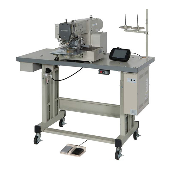
- Page 1 Industrial Sewing Machine TECHNICAL MANUAL Electronic Pattern Sewing Machine PLK - G Series Control Unit A180E604P02...
-
Page 3: Table Of Contents
Contents [1] For safe use_________________________________________________ [1]-1 [2] Precautions for use __________________________________________ [2]-1 [3] Installation__________________________________________________ [3]-1 [4] Names of each part, wiring and grounding _______________________ [4]-1 [5] Confirmation ________________________________________________ [5]-1 [6] Initial Settings of System Software (Model/Language Settings) ______ [6]-1 [7] Timing chart ________________________________________________ [7]-1 [8] Customized input/output ______________________________________ [8]-1... - Page 4 * The contents of this manual are subject to change without notice. * An utmost effort has been made to cover all points of operation in this manual. Contact Mitsubishi if you have any questions regarding the contents. COPYRIGHT(C)2008 MITSUBISHI ELECTRIC CORPORATION - 2 -...
-
Page 5: For Safe Use
[1] For safe use ■ For safe use Always observe the following matters to safely use the Mitsubishi industrial electronic sewing machine PLK-G Series. Before starting Before using this control unit, read all of the technical manuals carefully, and correctly use the unit following the manual. - Page 6 Enclosed units and accessories Connect the electrical enclosed units and accessories only to the positions indicated in the manual. Removal (1) Always turn the power switch OFF and disconnect the plug from the socket (power supply line) before removing the control box. (2) Do not pull out the cord when disconnecting the plug.
-
Page 7: Precautions For Use
[2] Precautions for use Warning 1. Do not place foot on the foot switch when turning the power ON. 2. Always turn the power OFF when leaving the sewing machine. 3. Do not inspect the control circuit with a tester. 4. - Page 8 9. The sewing machine will coast to a stop when the power is turned OFF or a power failure occurs during sewing machine operation. 10. Always align the connector shape and direction, and securely insert the connector. 11. If the position detector's connector dislocates, or the sewing machine is completely locked, the motor will be turned OFF automatically for a set time to prevent burning.
-
Page 9: Installation
[3] Installation 1. Installing the control box ●Insert the four bolts into the holes control box on the top plate and install the control box. Top view of control box installation area 4-Ø9 Top plate Installation bolt (Fix at four positions) Installation bolt (M8×60) Damper... -
Page 10: Names Of Each Part, Wiring And Grounding
[4] Names of each part, wiring and grounding CONR Warning 1.Front side USB(TYPE A) LED(red) with Protective cap Power LED(green) CONS RS-232C(MINI DIN) with Protective cap Front panel Function button Heat sink Cover installation screw (M4 screw) Cover Rating plate 2.Back side CONA CONB... - Page 11 3. Connecting the power connector Top plate Control box power Power connector (6-pole) Caution1: Always confirm the connector shape and insertion orientation and completely insert the power connector Control box into the control box. Always turn the power OFF before connecting the connector.
-
Page 12: Confirmation
[5] Confirmation 1. Before turning the switch ON (1)Are the power and capacity correct? (2)Are the connectors correctly inserted? ( Refer to “[12] Unit Wiring Diagram.” * Power connector from push-button switch * Connector for connection with sewing machine * Motor connector * Motor encoder connector * Foot switch connector * Other connectors (solenoid, etc.) -
Page 13: Initial Settings Of System Software (Model/Language Settings)
[6] Initial Settings of System Software (Model/Language Settings) 1.Model/Language Settings The model to be used and the language to be displayed need to be set. When you turn on the machine power with the system in an initial state, the “Model/Language Setting” screen appears. Perform the procedures below. - Page 14 (4)Setting table / Step file setting ►For Setting table/ step file setting, press If setting is not necessary, goto (5). ►Choose one of following buttons. Reads Setting table and Step file Reads Setting table only Reads Step file only Reads System file ,Setting table and Step file ►Connect USB memory [*1] , which above data is contained,...
- Page 15 (6)Re-turning on the power supply ►Turn the power off. ► After check the LED lamp on the front panel of the control box Is completely off, turn the power on. Check the LED lamp is OFF (7)Initial condition ► At initial condition, the message like a right picture is displayed.
-
Page 16: Timing Chart
[7] Timing chart 1.Thread trimming timing chart ·Timing for thread trimming output [T] : Program mode [Thread trimming/release timing] -- [LTM] T1~T5 Program mode [Thread trimming/release timing] -- [TRS] msec / deg Program mode [Thread trimming/release timing] -- [TRE] msec / deg ·Timing for thread release output [L] : Program mode [Thread trimming/release timing] -- [LLM] L1~L5... - Page 17 2.Timing chart for [Clamp of output ON/OFF delay setting] Clamp input 1~8 IF1~IF8 1A~8A 1B~8B Clamp output 1~8 OF1~OF8 3.Timing chart for [Priority of clamp] Clamp input 1 Clamp input 2 Clamp input 3 Clamp input 4 [WHY]=[OFF] Clamp output 1 Clamp output 2 Clamp output 3 Clamp output 4...
- Page 18 4.Timing chart for [Clamp link setting (CF)]=ON, [Valid Number of clamp setting (FN)]=4 Clamp input 1 Clamp output 1 Clamp output 2 Clamp output 3 Clamp output 4 Note: Halt switch is validated. 5.Timing chart for [Selection of pneumatic pressure two-step (AF2)]=ON Can not use other function in “Work holder”...
- Page 19 6.The divisions of clamp setting [OFB]=2 Setting of [FN],[CF],[F4BN],[F4SN] is invalidated when above setting. [WHY]=OF,[OFB]=2,[CF1]=ON,[CF2]=OF,[F21N]=4,[F22N]=3 When not using the clamp step input. Clamp input 1 Clamp input 2 Clamp input 3 Clamp input 4 Clamp input 5 Clamp input 6 Clamp input 7 Clamp input 8 Start input signal...
- Page 20 7.The divisions of clamp setting [OFB]=2 (When using the clamp step input.) Setting of [FN],[CF],[F4BN],[F4SN] is invalidated when above setting. [WHY]=OF,[OFB]=2,[CF1]=ON,[CF2]=OF,[F21N]=4,[F22N]=4 When using the clamp step input. The clamp step (forward direction) division 1 The clamp step (backward direction) division 1 The clamp step (forward direction) division 2...
- Page 21 8.The divisions of clamp setting [OFB]=4 Setting of [FN],[CF],[F21N],[F22N],[CF1],[CF2] is invalidated when above setting. Clamp(O1,O2),(O3,O4),(O5,O6),(O7,O8) is link movement when above setting. Only in this case, the block division operation is possible by the setting of [F4BN]. [WHY]=OF,[OFB]=4,[F4BN]=4 When not using the clamp step input. Clamp input 1 Clamp input 2 Clamp input 3...
- Page 22 9.The divisions of clamp setting [OFB]=4 Setting of [FN],[CF],[F21N],[F22N],[CF1],[CF2] is invalidated when above setting. Clamp(O1,O2),(O3,O4),(O5,O6),(O7,O8) is link movement when above setting. Only in this case, the block division operation is possible by the setting of [F4BN], and block step operation is possibleby the setting of [F4SN]. [WHY]=OF,[OFB]=4,[F4BN]=4,[F4SN]=4 When not using the clamp step input.
-
Page 23: Customized Input/Output
[8] Customized input/output 1.Customized input/output configuration diagram (Refer to page[8]-3) (Refer to page[8]-2) (Refer to page[8]-2) (Refer to page[8]-3) (Input port) Input Output (Output port) ·Terminal block ·Terminal block control control Virtual Virtual Physical Physical ·Connector ·Connector section section input output output input... - Page 24 2.Outline of customized input/output mode (A to E below correspond to A to E on the previous page.) (1)Customizing the input signal The ON/OFF signal input from the input port passes through the input control section (no operation, alternate operation, signal reversal), and is then stored in the physical input area corresponding to the input port.
- Page 25 4.Block diagram (input control section) Standard Physical input Alternate Logic changeover Operation changeover 5.Explanation of operations (input control section) The input signal passes through the A point, B point and C point of the input port, and finally is connected to the physical input Inputs the signal to the input port from an external source.
- Page 26 6.Block diagram (output control section) Operation ON delay Physical output selection Alternate ON delay Setting time OFF delay Logic changeover OFF delay Setting time Chopping Output port Full wave time Duty 100% ON Full wave time 66% ON(8ms ON/4ms OFF) Setting value x 100µs 66% ON(4ms ON/2ms OFF)...
- Page 27 delay setting B point When "invalid" is selected, the same signal as the A point will be output to the B point. When "valid" is selected, the waveform will rise after the {set value x } time (*1) set with the 100µs A point input waveform.
-
Page 28: Input/Output Signal
[9] Input/Output signal 1.Input signal setting table Code Function Specifications Clamp all step ON signal Whenever FSP input is on, clamp output [1],[2],[3],[4],[5],[6],[7],[8] turned on one by one. However, when [ Program mode > Clamp output > number of effective clamp (FN) ] is set to 1, FSP input is ineffective. Clamp all step OFF signal Whenever FSM input is on, clamp output [8],[7],[6],[5],[4],[3],[2],[1] turned off one by one. - Page 29 < sequel to INPUT SIGNAL > Code Function Specifications Fixed angel (rotation/reverse To confirm the needle thrust position, the needle is stopped just before the sewing material. Whenever BC input is ON, operation of [rotation] → [reverse rotation) signal rotation] → [rotation] is repeated. When the start switch is on afterwards, following sewing operation is started.
- Page 30 2.Output signal setting table Code Function Specifications When IO0 is on, OT0 output at the same time (same from OT1 to OTF ) OT0~OTF General purpose output 0 ~ F When FUN1 code is read while sewing operation, FN1 output is reversed. FN1~FNH Function code output 1 ~ H (same from FN2 to FNH) OF1~OF8 Clamp output 1 ~ 8...
-
Page 31: What Happened? Could It Be An Error
[10] What happened? Could it be an error? When an error occurs, the error code and corresponding message appear on the operation panel. Take a corrective action in accordance with the message. This section describes the errors and others that do not appear on the operation panel. - Page 32 [Case2] Nothing appears on the operation panel when you turn the power switch ON. (The front panel red (warning) LED is on or flickering.) Red (warning) LED flickering pattern ☼ - - - ☼ - - - ☼ - - - ☼ - - - ☼ - - - Blink once attern ☼...
- Page 33 [Case3] Though you turn the power switch ON and a screen appears on the operation panel, the screen display is incorrect. [Checking Items and Corrective Actions] Is the problem solved when you switch the screen or turn the power switch OFF and then ON again? ▪Reinstall the system.
- Page 34 [Action Method 1] Reinstalling the System The sewing machine is normally shipped with the system installed. However, if a reinstallation is required for some reasons and others, reinstall the system using a USB memory, and follow the method below. (1)Save the system data in a USB memory. (Refer to page[10]-8 [System data save to USB memory]) ►Copy the [ folder where the installed system datas are included, into the root directory of USB...
- Page 35 (5) After installation complete, [Machine type/Language setting] screen on the operationpanel is appeared. (6)Pull out USBmemory. (7)Language setting ►press ►Choose Language button, then press (8)Model setting ►press ►Choose Model button, then press [10] - 5...
- Page 36 (9)Setting table / Step file setting ►For Setting table/ step file setting, press If setting is not necessary, goto (10). ►Choose one of following buttons. Reads Setting table and Step file Reads Setting table only Reads Step file only Reads System file ,Setting table and Step file ►Connect USB memory [*1] , which above data is contained,...
- Page 37 (11)Initialize of set value ►To initialize set value, press (Setting will be returned to the factory setting) To exit without setting, press (12)Re-turning on the power supply ►Turn the power off. ► After check the LED lamp on the front panel of the control box Is completely off, turn the power on.
- Page 38 [System data save to USB memory (using copy tool)] [Outline] Coping system data of the CD-ROM to the USB memory by using copy tool. [Note] If “ ”, “ ”is already exist in the USB memory, they are over-written. (Please move necessary data to other folder or memory before using copy tool.) (1) Inset the PLK-G Document CD-ROM to your PC.
- Page 39 [System data save to USB memory (manual operation)] [Outline] Copy the [ ] folder where the installed system datas are included, into the root directory of USB memory. However, before installation to the sewing machine, please change the attribute of the data in the following way.
-
Page 40: Several Power Supply
[11] Several power supply 1.3Ø AC200V - 240V 50/60Hz White Black To control box White Green CONB Black Green Push button switch assay Green K14M47932202 60-9090-306-108-002 2.1Ø AC200V - 240V 50/60Hz (Except Europe) 60-9090-306-108-005 Blue Blue Brown To control box Brown CONB Green/... - Page 41 4.1Ø AC100V - 120V 50/60Hz Power unit PLK-B-PUC-A10 60-9090-306-108-005 60-9090-304-108-005 60-9090-305-108-005 Single-phase transformer 1Ø 600VA 60-9090-306-108-005 BKO-E3140H03 100V Black Black 200V Black Black Black White Brown White Black Brown Brown To control box Blue Black Brown Black CONB Blue Blue Green/Yellow Green Green...
-
Page 42: Unit Wiring Diagram
[12] Unit wiring diagram ■For connector pin details, refer to “[13] Connectors Layout” and “[14] Pin Number of Connectors.” [12]-1... -
Page 44: Connectors Layout
[13] Connectors layout [Back side of machine head] [Back side of control box] [front panel of the control box] [13] - 1... -
Page 45: Pin Number Of Connectors
[14] Pin number of connectors 1.Back side of control box/sewing machine CONG (XY axis encoder) CONA (Operation panel) Signal Pin No. Signal Pin No. RXD-IO RXD-PAL TXD-IO ENXAN ENXBN +12V ENYAN TXD-PAL ENYBN ENXAP CONB (Power supply) ENXBP Signal Pin No. ENYAP ENYBP CONH (Foot switch) - Page 46 CONL (General purpose iutput) Signal Initial setting Pin No. [IF2] Work holder input 2 CONR (USB) Signal Pin No. [NO] No operation VBUS [NO] No operation [NO] No operation [NO] No operation CONS (RS-232C) [NO] No operation Signal Pin No. [NO] No operation RXD1 RXD0...
- Page 47 (2)Output CON10 Printed Signal Pin No. character [T] Trim +24V DC24V power supply CON11 Printed Signal Pin No. character [W] Wiper +24V DC24V power supply CON12 Printed Signal Pin No. character [L] Thread release +24V DC24V power supply CON13 Printed Signal Pin No.
-
Page 48: Wiring Diagram Inside Control Box
[15] Wiring diagram inside control box... -
Page 49: Specifications
[16] Specifications 200~240V Power 200~240V 100~200V Single phase 380~415V source Single phase Single phase / 3-phase 3-phase / 3-phase 50/60Hz (Europe) 50/60Hz Specifications 50/60Hz 50/60Hz PLK-B-PUC- PLK-B-PUC- Power unit PLK-E-NU-20 Noise filter unit Model name XL-K756-20 Main Rated output 750W motor Rated speed 3,000rpm... - Page 50 MEMO...
- Page 52 FACTORY AUTOMATION SYSTEM TOKYO BLDG. 2-7-3,Marunouchi Chiyoda-ku Tokyo 100-8310,Japan FAX +81-3-3218-6821 New publication, effective OCT.2008. Specifications subject to change without notice...
Need help?
Do you have a question about the PLK - G Series and is the answer not in the manual?
Questions and answers