
Related Manuals for Mitsubishi Electric PLK-G10050R


Summary of Contents for Mitsubishi Electric PLK-G10050R
- Page 1 INDUSTRIAL SEWING MACHINE MODEL PLK-G5050R PLK-G10050R TECHNICAL MANUAL SEWING MACHINE HEAD BASIC A180E700P02...
- Page 2 FOR SAFE USE Before the installation, operation, and inspection for this product, read the “FOR SAFE USE” and the technical manuals carefully. Also read the other technical manuals, “Control Unit” and “Operation Panel” describing some instructions, which are not in this manual, and use the sewing machine properly. SAFETY INDICATIONS Indicates that incorrect handling may cause hazardous conditions, resulting DANGER...
- Page 3 SAFETY PRECAUTIONS DANGER To prevent from receiving an electric shock, always turn off a power switch and unplug power supply when opening a control box, and then open after ten minutes passes. CAUTION USAGE ENVIRONMENT Please do not operate the sewing machine under the following conditions. (1) In the ambient temperature of 35 degrees (95°F) or more than 35 degrees, or the ambient temperature of 5 degrees or less than 5 degrees (41°F).
- Page 4 SEWING (1) Please make sure to turn the power switch off before installing or replacing needles. (2) Please pay attention for the fingers not to be injured by the needle point. (3) Please make sure to turn power switch off before lubricating. (4) Please pay attention that oil does not get on your skin or in your eyes as it may cause an inflammation.
-
Page 5: Table Of Contents
CONTENTS 1. STRUCTURE OF THE SEWING MACHINE···································· 2. INSTALLATION········································································ 2-1. Installation of the electric cables······························································· 2-2. Connection of the air tube······································································· 2-3. Installation of the thread stand································································· 2-4. Installation of the eye guard···································································· 2-5. Installation of the spindle motor································································ 3. LUBRICATION········································································· 3-1. -
Page 6: Structure Of The Sewing Machine
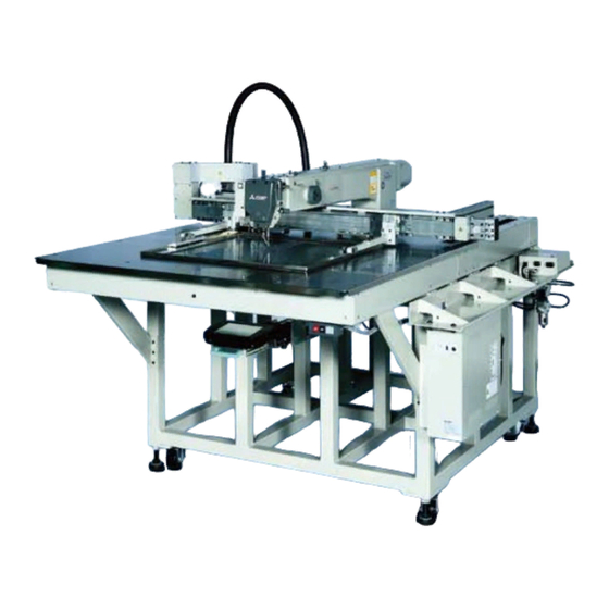
1. STRUCTURE OF THE SEWING MACHINE PLK-G5050R/G10050R electronic pattern sewing machine consists of the following main parts. <2> <1> <8> <3> <9> <5> <10> <4> <7> <6> <1>: Sewing machine head <2>: Main shaft motor <3>: Halt switch <4>: Control box <5>: Operation panel <6>: Work holder foot switch <7>: Start foot switch <8>: Thread stand <9>: Sewing machine table <10>:Power switch - 1 -... -
Page 7: Installation
2. INSTALLATION CAUTION (1) Please have some specialists, who have enough experience for the sewing machine installations, install the sewing machine. (2) Please have a Qualified Electrician perform necessary electric wiring. (3) Please do not operate until the sewing machine is repaired when any damage or fault is found on the sewing machine at the installation. -
Page 8: Installation Of The Thread Stand
2-3. Installation of the thread stand (1) Assemble the parts of the thread stand as shown on the figure. (2) Fit the thread stand into the hole at the far right on the table stand with the nut (No.13) and the washers (No.12) and the collar (No.14). -
Page 9: Installation Of The Spindle Motor
2-5. Installation of the spindle motor (1) If the spindle motor (No.1) has been removed from the machine for the adjustment or the like, fix the spindle motor as the procedure described below. (2) Set the pin (No.3) position of the bushing to the motor mark (No.2). (3) Adjust the clearance between the motor and the coupling (No.4). -
Page 10: Filling The Oil Tank
3-1. Filling the oil tank Pour the oil through the oil hole (No.1) to the oil tank (No.2) on the machine arm. Pour the oil hole (No.3) to the oil tank for hook (No.4) on the machine bed. Pour the oil hole (No.5) to the oil tank for gear box (No.6) on the machine bed. - Page 11 MEMO...
- Page 12 Printed in Japan...
Need help?
Do you have a question about the PLK-G10050R and is the answer not in the manual?
Questions and answers