
Related Manuals for Mitsubishi Electric PLK-J2516R-YU


Summary of Contents for Mitsubishi Electric PLK-J2516R-YU
- Page 1 INDUSTRIAL SEWING MACHINE MODEL PLK-J2516R-YU TECHNICAL MANUAL SEWING MACHINE HEAD A180E803P02...
- Page 2 FOR SAFE USE Before the installation, operation, and inspection for this product, read the “FOR SAFE USE” and the technical manuals carefully. Also read the other technical manuals, “Control Unit” and “Operation Panel” describing some instructions, which are not in this manual, and use the sewing machine properly. SAFETY INDICATIONS Indicates that incorrect handling may cause hazardous conditions, resulting DANGER...
- Page 3 SAFETY PRECAUTIONS DANGER To prevent from receiving an electric shock, always turn off a power switch and unplug power supply when opening a control box, and then open after ten minutes passes. CAUTION USAGE ENVIRONMENT Please do not operate the sewing machine under the following conditions. (1) In the ambient temperature of 35 degrees (95°F) or more than 35 degrees, or the ambient temperature of 5 degrees or less than 5 degrees (41°F).
- Page 4 SEWING (1) Please make sure to turn the power switch off before installing or replacing needles. (2) Please pay attention for the fingers not to be injured by the needle point. (3) Please make sure to turn power switch off before lubricating. (4) Please pay attention that oil does not get on your skin or in your eyes as it may cause an inflammation.
-
Page 5: Table Of Contents
CONTENTS 1. STRUCTURE OF THE SEWING MACHINE···································· 2. SPECIFICATIONS····································································· 3. INSTALLATION········································································ 3-1. Preparation of the table·········································································· 3-2. Preparation of the steel stand·································································· 3-3. Installation of the control box··································································· 3-4. Installation of the operation panel····························································· 3-5. Installation of the power switch and foot switch············································ 3-6. - Page 6 5. PROPER OPERATION······························································ 5-1. Setting of the main servo motor upper positon············································· 5-2. Installation of the needle········································································· 5-3. Threading the needle thread··································································· 5-4. Winding the bobbin thread······································································ 5-5. Setting the bobbin················································································· 5-6. Setting the bobbin case·········································································· 5-7. Operation of the halt switch····································································· 5-8.
- Page 7 7. VARIOS ADJUSTMENT····························································· 7-1. How to exchanging the tension spring of the needle thread tensioner unit········ 7-2. Adjustment of the detector position of the presser foot unit···························· 7-3. How to replace with a special pressor foot················································· 7-4. Adjustment of the pressor foot holder position············································ 7-5.
-
Page 8: Structure Of The Sewing Machine
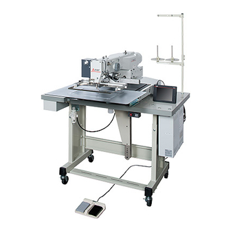
1. STRUCTURE OF THE SEWING MACHINE PLK-J2516R-YU electronic pattern sewing machine consists of the following main parts. <10> <2> <1> <3> <9> <5> <8> <4> <7> <6> <1>: Sewing machine head <2>: Main shaft motor <3>: Halt switch <4>: Control box <5>: Operation panel <6>: Work holder switch <7>: Start switch <8>: Gas spring... -
Page 9: Specifications
Maximum number of needles 20,000 per pattern Storable sewing data item 9,000 patterns Data memory USB memory Type of motor Mitsubishi Electric 750W direct servo motor Work holder lift 30 mm Needle bar stroke 40.0 mm Thread take up lever stroke 73.0 mm... -
Page 10: Installation
3. INSTALLATION CAUTION (1) Please have some specialists, who have enough experience for the sewing machine installations, install the sewing machine. (2) Please have a Qualified Electrician perform necessary electric wiring. (3) Please do not operate until the sewing machine is repaired when any damage or fault is found on the sewing machine at the installation. -
Page 11: Preparation Of The Steel Stand
(2) When fitting the caster to the steel stand, the steel stand has to be strong enough to withstand the weight and vibration of the sewing machine. (3) If the steel stand is MITSUBISHI PLK-J2516R-YU original, assemble the steel stand with the assembling instructions enclosed in the packing. -
Page 12: Installation Of The Oil Pan
3-6. Installation of the oil pan (1) Remove the oil pan (No.1) from the accessory box then, set the oil bottle (No.2) to the oil pan (No.1). (2) Put the oil pan at the position shown on the figure then, fix the oil pan with staples (No.3). (3) Set the damper cushions (No.4) to the table. -
Page 13: Installation Of Gas Spring
3-8. Installation of gas spring DANGER (1) The sewing machine is heavy. For the safety, please make sure to install the sewing machine head by more than one person. (2) When tilting the sewing machine, please stand at the hinge side and hold the sewing machine with both hands. -
Page 14: Installation Of The Tilting Detect Switch
(7) Attach the cover (No.11) to the gas spring unit with the screws (No.12). <11>: Cover <12>: Screw (six screws) <11> <12> 3-9. Installation of the tilting detect switch (1) Install the switch units (No.1) with the Screws (No.2). (2) Adjust the switch units (No.1) position so that the machine table push the switch when the machine head in initial position and turns on the switch. -
Page 15: Connection Of The Electric Cables
3-10. Connection of the electric cables CAUTION (1) Please make sure to ground the place where there is a mark. Failure to do so may cause electric shock and/or malfunction. Connect the machine head and the control box with cables as following below instruction. Connect each connector fully to ensure sufficient contact. -
Page 16: How To Remove The Motor Cover
3-10-1. How to remove the motor cover (1)Remove the five of screws (No.2) and remove the motor cover (No.1). <2> <1> <1>: Motor cover <2>: Screw 3-10-2. Connection of the PF axis cables (1) Prepare the PF axis motor cable (No.1) and PF axis encoder cable (No.2) which housed in the motor cover and wiring that to the back side of the table by passing through the square hole. -
Page 17: Connection Of The Xy Axis Cables
3-10-3. Connection of the XY axis cables (1) Install the XY motor cable (No.1) to the sewing machine with nylon clip FG (No.3) and screw (No.4) which are enclosed in accessory box. (2) Install the XY encoder cable (No.2) to the sewing machine with nylon clip (No.5) and screw (No.6) which are enclosed in accessory box. -
Page 18: Connection Of The Main Servo Cables
3-10-4. Connection of the main servo cables (1) Wiring the main servo motor cable (No.1) and main servo encoder cable (No.2) to the back side of the table by passing through the long hole. (2) Connect each of the main servo motor cable (No.1) and main servo encoder cable (No.2) to CON B and CON M connector which has control box. -
Page 19: Connection Of The I/F Board Cables
3-10-5. Connection of the I/F board cables (1) Connect the I/F board signal cable (No.1) to the I/F board connector which enclosed in accessory box. (2) Connect the I/F board power cable (No.2) to the I/F board connector which enclosed in accessory box. -
Page 20: Connection Of The Optional Output Connector
3-10-6. Connection of the optional output connector (1) Connect the optional output connector (No.1) to the I/F board connector. Note If not connected this connector, the oil discharging function does not work. <1> <1>: Optional output connector 3-10-7. Fixing of the cables (1) Attach the two of tie holders (No.1) with wood screws (No.2) which enclosed in accessory box. -
Page 21: Connection Of The Air Tube
3-11. Connection of the air tube 3-11-1. Installation of the filter regulator and air piping (1) Attach the air presser regulator assembly (No.1) underneath the table with the wood screws (No.2). The prepared holes are provided for the wood screws on the rear surface of the table. (2) Cut the part of sizeφ8 air tube (No.3) enclosed in the accessory box into about 1 meter length then, insert one end of this air tube into the intake air fitting (No.8) of the magnet valve assembly (No.7) The magnet valve assembly (No.7) is located at the left side surface of the sewing machine head. -
Page 22: Piping Of The Oil Drainage Tube
3-11-2. Piping of the oil drainage tube According to following procedures, piping the oil discharging unit which is capable of reducing the excess of lubrication oil. (1) Prepare the oil drainage tube (No.3) which connected with air ejector (No.2) which is also connected with magnet valve assembly (No.1). - Page 23 (2) While paying attention to the matters described in previous paragraph [3-8. Installation of gas spring]. (3) Drive the two of staples (No.4) to the table. In this time please check if the oil drainage tube (No.3) is to be arranged as below drawing in advance. To prevent damage to the oil drainage tube (No.3), not to drive the staples (No.4) in state of the oil drainage tube (No.3) is inserted into it.
-
Page 24: Installation Of The Thread Stand
3-12. Installation of the thread stand (1) Assemble the parts of the thread stand as shown on the figure. (2) Fit the thread stand into the hole at the far right on the machine table with the nut (No.13) and the washer (No.12). -
Page 25: Lubrication
4. LUBRICATION 4-1. Filling the oil tank CAUTION (1) Please make sure to turn power switch off before lubricating. (2) Please pay attention that oil does not get on your skin or in your eyes as it may cause an inflammation. -
Page 26: Proper Operation
5. PROPER OPERATION 5-1. Setting of the main servo motor upper positon [Notice] When install the removed main servo motor for adjustment or the like, it is necessary to reset the main servo motor upper positon. Please refer to following procedures reset the main servo motor upper position. - Page 27 (5) Following the screen indication, set up the main motor up position. After the completion of setting, press the icon and then press the icon. (6) After adjustment turn the power switch off. - 20 -...
-
Page 28: Installation Of The Needle
5-2. Installation of the needle CAUTION (1) Please make sure to turn the power switch off before installing or replacing needles. (2) Please pay attention for the fingers not to be injured by the needle point. (1) Loosen the set screw (No.1) then, insert a new needle (No.2) until the needle head is reached the end of the hole of the needle bar (No.3). -
Page 29: Threading The Needle Thread
5-3. Threading the needle thread CAUTION (1) Please turn the power switch off when threading a needle. Thread the needle thread as shown on the figure. - 22 -... -
Page 30: Winding The Bobbin Thread
5-4. Winding the bobbin thread CAUTION (1) Please do not touch the rotating part during winding thread. Doing so may cause injury and/or the machine failure. (1) Route the thread as shown in the below figure then, wind the thread to the bobbin (No.1) in the direction of “a”... -
Page 31: Setting The Bobbin
5-5. Setting the bobbin (1) Set the bobbin (No.2) into the bobbin case (No.1). (2) Pull the bobbin thread (No.3) into the slit (No.4) and pass through the thread hole (No.5). At this time, pull the bobbin thread (No.3) then, check with the bobbin (No.2) if it is rotated to the arrow direction. -
Page 32: Operation Of The Halt Switch
5-7. Operation of the halt switch (1) If accidents such as a thread breakage, needle breakage and others happened during the sewing, press the halt switch (No.1) immediately. The sewing machine stops instantly. (2) To cancel the halt state, press the halt switch again. (3) When continuing sewing, step on the grey foot switch to restart at the halted position. -
Page 33: Adjustment Of Upper Thread Tension
5-9. Adjustment of upper thread tension Adjust the upper thread tension corresponding to the bobbin thread tension. The upper thread tension becomes tight when tightening the thread tension adjusting nut (No.1) clockwise, and the upper thread tension becomes loose when loosening the thread tension adjusting nut counterclockwise. NOTE It is possible to adjust the upper thread tension automatically. -
Page 34: Standard Adjustment
6. STANDARD ADJUSTMENT CAUTION (1) Please make sure to turn the power switch off before adjusting the sewing machine. (2) When adjusting the sewing machine with the power switch on, please be careful not to step on the foot switch by mistake. (3) Please be careful not to be injured by a sharp part such as the needle and the hook point. -
Page 35: Adjustment Of The Position Between The Needle And The Rotating Hook
6-2 Adjustment of the position between the needle and the rotating hook (1) Turn the power switch OFF. (2) Open the cylinder cover (No.1). (3) Remove the bobbin case (No.2). (4) Remove the sliding plate (No.3). (5) Loosen the three of hook set screws (No.4). <3>... - Page 36 (7) Turn the hook by hand and stop it at the position where the hook point (No.7) meets with the center line of the needle (No.8). <7> <8> <7>: Hook point <8>:Needle (8) Move the hook by hand and adjust the clearance between the hook point and the needle to be about 0.05 mm.
-
Page 37: Adjustment Of The Hook Positioner's Position
6-3. Adjustment of the hook positioner’s position (1) Remove the sliding plate. (2) Loosen the hook positioner set screw (No.4) and adjust the hook positioner (No.1) position to align the right side of the projection (No.3) with the right side of the needle (No.2) as shown on the figure. (3) After the adjustment, securely tighten the hook positioner set screw (No.4) and put the sliding plate back on the sewing machine. -
Page 38: Adjustment Of The Oil Lubrication For The Rotating Hook
6-4 Adjustment of the oil lubrication for the rotating hook (1) Open the cylinder cover (No.1). (2) Tighten the oil flow adjusting screw (No.2) lightly by fingers or a screw driver until it is stopped the turn. NOTE Do not tight the oil flow adjusting screw (No.2) too much. (3) Adjust the oil flow in the range of one reverse turn from the deadlock position of the oil flow adjusting screw (No.2). -
Page 39: Adjustment Of The Oil Lubrication For The Machine Head
6-5. Adjustment of the oil lubrication for the machine head (1) Amount of oil supply for the machine head is controlled by specified injection time for every specified stitch number. The lubrication oil is injected by compressed air. Press the on the standard screen, and press the icon. -
Page 40: Setting Of The Presser Foot Movement
6-6. Setting of the presser foot movement It is not necessary to adjust the presser foot movement with operating the mechanical unit. Please refer to the instructions OPERATION PANEL technical manual and change each setting in matching with the sewing conditions. (1) Adjustment of the presser foot height position: Please refer to [8] Controlling the Presser Foot. -
Page 41: Adjustment Of The Thread Take Up Spring
6-8. Adjustment of the thread take up spring 6-8-1. Adjusting movable range of the thread take up spring (1) To adjust the thread take up spring (No.1), loosen the stopper stop screw (No.2) and move the stopper (No.3). When moved the stopper (No.3) in the arrow direction, movable range of the thread take up spring (No.1) is increased. -
Page 42: Adjustment Of The Thread Tail After The Trimming
6-9. Adjustment of the thread tail after the trimming (1) Adjust the thread tail with the pre-tension (No.1). (2) When turning the nut (No.2) clockwise, the thread tail becomes shorter. When turning the nut (No.2) counterclockwise, the thread tail becomes longer. <1>... -
Page 43: Changing The Work Holder
6-11 Changing the work holder (1) Remove the work holder (No.1) by pressing it down from the engaged area with the pin (No.2) of the clamp adapter. (2) Prepare another work holder and securely engaged its U shaped mortise (No.3) with the pin (No.2) of the clamp adapter. -
Page 44: Varios Adjustment
7. VARIOS ADJUSTMENT CAUTION (1) Please make sure to turn the power switch off before adjusting the sewing machine. (2) When adjusting the sewing machine with the power switch on, please be careful not to step on the foot switch by mistake. (3) Please be careful not to be injured by a sharp part such as the needle and the hook point. - Page 45 (3) Pull out the thumb screw (No.2) from tensioner shaft (No.5). In this time the bearing (No.6) is removed too. (4) Remove the tension spring (No.1). (5) After exchanging the tension spring (No.1) back the bearing (No.6) and thumb screw (No.2) in order. Then tighten the set screw (No.4) and screw (No.3) in order.
-
Page 46: Adjustment Of The Detector Position Of The Presser Foot Unit
7-2. Adjustment of the detector position of the presser foot unit According to following procedures, adjust the detector position in case of parts replacement etc. NOTE The presser foot lifting position is setting by 18 mm from top of the sliding plate. NOTICE The presser foot movement is based on the origin detection position. - Page 47 (4) Detector (No.4) is installed in machine head. Detector (No.4) detects end of the presser bar (No.5). Before adjustment, it is necessary to make sure following items. <7> <4> <5> <4>: Detector <6> <5>: End of presser bar <6>: Fixing screw <7>: Detector bracket (a) Press the from standard screen and check if the presser foot height value (ZTHK) is [***].
- Page 48 (5) Loosen the fixing screw (No.6) and move the detector bracket (No.7) upward in advance then tighten the fixing screw (No.6) temporally. (6) Remove the sewing material and work holder and any parts. After make sure the work environment safety, turn the power switch on. (7) After finish the origin movement, make sure the clearance between the bottom of presser foot and top of the sliding plate is 18 mm.
-
Page 49: How To Replace With A Special Pressor Foot
(9) Press the presser foot down icon and check the gap between bottom of presser foot and top of sliding plate is 0 to 0.2 mm. If there is any collision sounds when down the presser foot, please readjust above. If the gap more than 0.2 mm, please readjust too. - Page 50 (2) Press the icon from the [PF position adjustment] screen. (3) Replace the presser foot with standard one. (4) Press the icon and down the presser foot to the top of the needle plate. In this time, set the gap between bottom of presser foot and top of needle plate to be 0 to 0.2 mm. The screen indicates ZNPP default value (Upper) and current value (Lower).
- Page 51 (5) After the completion of setting, press the memory icon and then press the icon. NOTE The ZNPP value is flickering until press the icon. (6) Following the screen indication, put the power switch off. - 44 -...
-
Page 52: Adjustment Of The Pressor Foot Holder Position
7-4. Adjustment of the presser foot holder position (1) Turn off the machine power and down the presser foot (No.7) by hand to the top of the sliding plate. (2) Loosen the each of set screws (No.5) which has presser foot holder (upper) (No.3) and presser foot holder (lower) (No.4). -
Page 53: Adjustment Of The Thread Trimmer
7-5 Adjustment of the thread trimmer 7-5-1 Structure of the thread trimmer mechanism The thread trimmer mechanism of sewing machine is shown on the figure. <4> <1> <12> <3> <2> <11> <5> <9> <8> <10> <7> Bottom side view <6> <1>: Knife mounting unit <2>: Knife bracket <3>: Trimming cam <4>: Air cylinder <5>: Stopper <6>: Cam follower crank 2 <7>: Cam follower crank 1 <8>:Knife driving shaft <9>:Driving crank <10>: Movable knife <11>: Stationary knife <12>: Thread guide... -
Page 54: 7-5-2.2 Mutual Relation Among The Movable And Stationary Knife Edge
(2) Knife mounting unit Under the condition that the rotating hook and the hook positioner are removed, attach the knife mounting unit (No.1) with the set screw (No.2). <1>: Knife mounting unit <2> <2>: Set screw <1> 7-5-2.2 Mutual relation among the movable and stationary knife edge (1) Rotate the movable knife (No.1) by hand when it is engaged with the stationary knife (No.2), there is 0.3mm space between the movable and stationary knife edges. -
Page 55: 7-5-2.3 Connection Of The Knife Bracket And The Driving Crank
7-5-2.3 Connection of the knife bracket and the driving crank (1) Connect the knife bracket (No.1) and the driving crank (No.2) with the link (No.3). (2) Loosen the driving crank set screw (No.4) and adjust the attaching position of the driving crank (No.2) in the right and left direction so that the link (No.3) can contact with the same flat surface of the knife bracket (No.1) and the driving crank (No.2) without any distortion. -
Page 56: 7-5-2.5 Adjustment Of The Mounting Position Of The Air Cylinder
7-5-2.5 Adjustment of the mounting position of the air cylinder (1) Attach the thread trimmer air cylinder (No.1) by fixing with the bolt (No.2). When the thread trimmer air cylinder (No.1) is released, there will be a clearance of approx. 1mm at section A . To adjust this clearance, loosen the set screw (No.4) for the mounting plate (No.3), and move the entire mounting plate (No.3). - Page 57 (1) Loosen 2 set screws (No.9) of the thread trimmer cam (No.8).Remove the slide plate and place the 4mm thickness gauge (No.10) on the top of sewing machine bed. Move the needle bar downward from its upper position and slide the gauge (No.11) in between the needle bar and the 4mm thickness gauge (No.10).
-
Page 58: 7-5-2.7 Adjustment Of The Knife Engagement
7-5-2.7 Adjustment of the knife engagement (1) The standard position for the movable and stationary knife The standard mutual position for the movable knife (No.1) and stationary knife (No.2) is as shown on the figure. (2) Adjustment of the amount for the knife engagement Activate the thread trimmer air cylinder, and rotate the upper shaft. - Page 59 (3) Adjustment of the engaging presser for the knives a) The engaging presser for the movable knife (No.1) and stationary knife (No.2) can be controlled with adjusting the height of the stationary knife (No.2). When the movable knife (No.1) is rotated, the contact of the both knives starts from the position where the distance between the edge of the stationary knife (No.2) and the cut out line of the movable knife (No.1) is 3mm.
-
Page 60: Adjustment Of The X-Y Table Detector
7-6. Adjustment of the X-Y table detector 7-6-1. Adjustment of the X-Y mechanical home position The mechanical home position (No.1) is fixed at the center of the sewing area as the factory default setting. The machine can be moved within the area (No.2) covered with diagonal lines. <2>... -
Page 61: Adjustment Of The X Direction
7-6-2. Adjustment of the X direction (1) Turn the power switch off. (2) Remove the covers on the top of the sewing machine bed. (3) The mechanical home position of the X direction is the position where the detector (No.2) can detect the edge of the detector plate X (No.1). -
Page 62: Adjustment Of The Y Direction
7-6-3. Adjustment of the Y direction (1) Turn the power switch off. (2) The mechanical home position of the Y direction is the position where the detector (No.2) can detect the edge of the Y drive shaft (No.1). (3) For the adjustment of the Y direction mechanical home position, loosen the detector set screw (No.3) then, move the detector to the arrow direction as shown on the figure. -
Page 63: Maintenance
8. MAINTENANCE CAUTION (1) Please make sure to turn the power switch off before cleaning the sewing machine. (2) Please pay attention to that staining your skin or eyes with oil may cause an inflammation. 8-1. Cleaning Remove the dust and the thread waste sticking regularly. 8-2. -
Page 64: Disposing Of Oil Waste
8-3. Disposing of oil waste If the oil bottle (No.1) is full filled with waste oil, remove the oil bottle and dispose it regularly. <1>: Oil bottle <1> - 57 -... -
Page 65: Troubleshooting
9. TROUBLESHOOTING CAUTION (1) Please make sure to turn the power switch off before adjusting the sewing machine. (2) If the adjustment is required while the power switch on, do not step on the foot switch by mistake. Condition Cause Corrective action Reference Upper thread tension is too... - Page 66 Frequent skip stitching Clearance between needle Adjust clearance between happens. and hook is too big. needle and hook properly. Timing of needle and hook is Adjust position of needle and not proper. hook properly. Needle is bent. Change needle. Needle is at wrong position. Fix position properly.
- Page 67 Upper thread tension is too Stitch forming is loose. Adjust upper thread tension. loose. Bobbin thread tension is too Adjust bobbin thread tension. loose. Strength of thread take up Adjust strength of thread take 6-8-2 spring is inadequate. up spring. Presser foot position is not Adjust presser foot position proper.
- Page 69 10-2. Steel stand drawings MEMO If the steel stand is not MITSUBISHI original, produce the parts with reference to the following drawings. <2> <1> <3> <6> <5> <7> <4>...
- Page 70 Stand part <1>···Thickness 2mm Stand part <2>···Thickness 2mm...
- Page 71 Stand part <3>···Thickness 2mm Stand part <4>···Thickness 2mm Stand part <5>···Thickness 5mm Stand part <6>···Rubber thickness 2.5mm Stand part <7>···Permissible load more than 60kg (Per wheel)
- Page 72 Printed in Japan...
Need help?
Do you have a question about the PLK-J2516R-YU and is the answer not in the manual?
Questions and answers