Table of Contents
Advertisement
Quick Links
This manual specifies the installation and operation
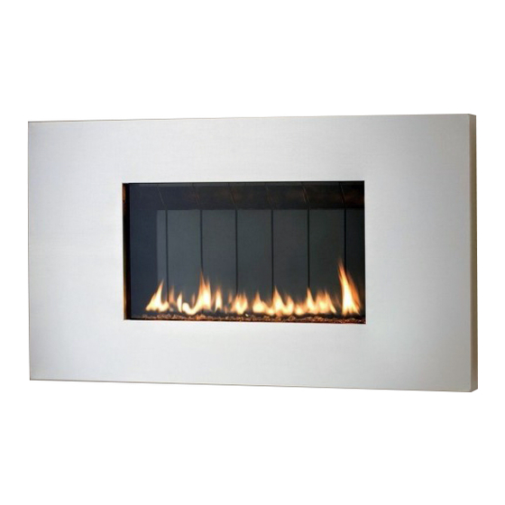
requirements for the West End Wall Fire
(COPRECI) Model Nos. SL-26N, SL-26P.
This appliance may be installed in an aftermar-
ket, permanently located manufactured home
(USA only) or in a mobile home, where not pro-
hibited by local codes.
This appliance is for use only with the type of gas
indicated on the rating plate. This appliance is
not convertible for use with other gases, unless a
certified conversion kit is used.
Ce manual est disponsible en Français sur demande.
Report # 361-F-01-5
INSTALLER: Leave this manual with the appliance.
CONSUMER: Retain this manual for future reference.
WEST END
Wall Fire
Installation & Operation
Guide
WARNING: If the information in these in-
structions is not followed exactly, a fire or
explosion may result causing property dam-
age, personal injury or loss of life.
- Do not store or use gasoline or other flam-
mable vapors and liquids in the vicinity of this
or any other appliance.
WHAT TO DO IF YOU SMELL GAS
Do not try to light any appliance.
Do not touch any electrical switch; do not
use any phone in your building.
Immediately call your gas supplier from a
neighbor's phone. Follow the gas sup-
plier's instructions.
If you cannot reach your gas supplier, call
the fire department.
- Installation and service must be performed by
a qualified installer, service agency or the gas
supplier.
Advertisement
Table of Contents

Subscribe to Our Youtube Channel
Related Manuals for European Home WEST END


Summary of Contents for European Home WEST END
- Page 1 This manual specifies the installation and operation - Do not store or use gasoline or other flam- mable vapors and liquids in the vicinity of this requirements for the West End Wall Fire or any other appliance. (COPRECI) Model Nos. SL-26N, SL-26P.
- Page 2 : Assurez-vous de bien suivre AVERTISSEMENT les instructions données dans cette notice pour réduire au minimum le risque d’incindie ou d’explosion ou pour éviter tout dommage matériel, toute blessure ou la mort. Ne pas entreposer ni utilizer d’essence ni d’autres vapeurs ou liquides inflammables dans le voisinage de cet appareil ou de tout autre appareil.
-
Page 3: Table Of Contents
WARRANTY INFORMATION WE STRONGLY SUGGEST THAT YOU READ THIS MANUAL THOROUGHLY BEFORE BE- GININNG THE INSTALLATION OF THE WEST END DIRECT VENT GAS FIREPLACE. AL- THOUGH THE BASIC REQUIREMENTS FOR THE INSTALLATION OF ALL DIRECT VENT GAS FIREPLACES ARE SIMILAR, EACH SPECIFIC PRODUCT HAS ITS OWN UNIQUE SET- UP AND INSTALLATION REQUIREMENTS THAT MUST BE FOLLOWED EXACTLY. -
Page 4: Important Safety Information
IMPORTANT SAFETY INFORMATION The installation must conform with local codes or, in the absence of local codes, with the National Fuel Gas Code, ANSI Z223.1 or the Canadian Installation Code, CAN/CGA B149. A manufactured home (USA only) or mobile home OEM installation must conform with the Manufactured Home Construction and Safety Standard, Title 24 CFR, Part 3280 or when such a standard is not applica- ble, the Standard for Manufactured Home Installations, ANSI/BCSBCS A225.1, or Standard for Gas Equipped Recreational Vehicles and Mobile Housing, CSA Z240.4. -
Page 5: Specifications
2007 Vented Gas Fireplace Heaters and CAN/CGA-2.17-M91, Gas-Fired Appliances for Use At High Altitudes. The WEST END Wall Fire is approved for installation at elevations up to 2000 feet in the U.S. and 1370 meters (4500 feet) in Canada without change. If your installation is at an elevation greater than these, con- sult with the local authority having jurisdiction for gas product installations to determine their specific re- quirements for high altitude installations. -
Page 6: Installation Requirements
INSTALLATION REQUIREMENTS Several issues must be addressed when selecting a suitable location for your fireplace. The minimum clear- ances to combustible construction are listed below. In addition, access to the gas supply must be consid- ered. The location of the fireplace will also affect the venting requirements and you must be certain the lo- cation will allow compliance with the venting requirements shown on page You must also insure that your installation provides adequate accessibility clearance for servicing and proper operation. -
Page 7: Massachusetts Requirements
INSTALLATION REQUIREMENTS The gas fireplace is shipped with a plugged 3/8” NPT connection. The gas supply piping should have a separate gas shutoff valve and a 1/8” NPT plugged tapping upstream of the valve. The stove and its main control valve must be disconnected from the gas supply piping system during any pressure testing of that system at test pressures in excess of 1/2 psi (3.5 kPa). -
Page 8: Venting
VENTING The West End Direct Vent Gas Fireplace has been tested and listed for installation with 4” X 6 5/8” Simp- ® ® son DuraVent GS/Pro Selkirk Direct-Temp , Security Secure Vent™, AmeriVent Direct™ Metal Fab Direct t venting components. Although you may use the pipe components (straight pipe, Vent and ICC EXCELDirec elbows, etc.) from any of the listed manufacturers, you may only use the vent terminations (caps) listed in... - Page 9 USING THE VENTING CHARTS The location of the vent termination must meet the requirements of the current edition of ANSI Z223.1/ NFPA 54, National Fuel Gas Code or CAN B419.1, Natural Gas and Propane Installation Code and the requirements shown on page 15 of this manual. Just as with any other vented device, vertical vent rise creates draft (negative pressure) in the firebox as the exhaust gases heat up.
- Page 10 NATURAL GAS VENTING CHART AIR RESTRICTOR EXHAUST RESTRICTOR 1— 6 TABS OPEN A or B NU = NOT USED NU = NOT USED VERTICAL TERMINA- TIONS NOT ALLOWED VERTICAL RISE IN FEET...
- Page 11 LP GAS VENTING CHART AIR RESTRICTOR EXHAUST RESTRICTOR 1— 6 TABS OPEN A or B NU = NOT USED NU = NOT USED VERTICAL TERMINA- TIONS NOT ALLOWED VERTICAL RISE (FEET)
-
Page 12: Venting Chart Worksheet
VENTING CHART WORKSHEET A. FUEL TYPE: NATURAL GAS LP GAS (PROPANE) B. TOTAL VERTICAL VENT RISE (MEASURED FROM HORIZONTAL CENTERLINE OF VENT OPENING ON THE BACK OF THE FIREPLACE TO THE HORIZONTAL CENTERLINE OF THE VENT CAP (FOR HORIZONTAL VENT CAPS) OR TO THE FLANGE ON THE CAP (FOR VERTI- CAL CAPS)): _____________ FEET C. -
Page 13: Use Natural Gas Chart Settings For
VENTING CHART WORKSHEET EXAMPLES A. Fuel: Natural Gas A. Fuel: LP Gas B. Total Vertical Vent Rise: 0 feet B. Total Vertical Vent Rise: 1 feet C. Total Horiz. Vent Run (Actual): 0 feet C. Total Horizontal Vent Run (Actual): 3 feet D. - Page 14 VENTING The illustration below shows some of the many ways the fireplace may be installed in the home. This in- cludes interior and exterior wall installations, corner installations and horizontal and vertical vent termina- tions. HORIZONTAL TERMINATION VERTICAL TERMINATION...
-
Page 15: Vent Terminal Clearances
VENT TERMINAL CLEARANCES Venting terminals shall not be recessed into a wall or siding. -
Page 16: Assembly & Installation
ASSEMBLY & INSTALLATION UNPACKING AND INSTALLING THE WALL MOUNT FIREPLACE The fireplace components are shipped in three cartons. By now, you will have opened the top of the first carton and re- moved the glass protector and this manual. The second carton TUBE 2 TUBE 1 contains the vent starter pipe, vent heat shields and air and ex-... - Page 17 ASSEMBLY & INSTALLATION Before you begin the fireplace mounting process there are several important installation requirements that must be met. Careful planning will make the installation easier to accomplish and will reduce the chances of encountering problems after you start. 1.
- Page 18 ASSEMBLY & INSTALLATION Once you are certain that the location you have chosen meets all the necessary mounting and safety require- ments, you can begin the installation. 1. Tape or pin the installation template to the wall in the position where the fireplace is to be LEVEL mounted.
- Page 19 1 through 6. Vent Pipe Heat Shields Special telescoping double heat shields for the vent pipe are provided with the West End fireplace. These heat shields are a critical part of a safe installation. They are designed to protect combustible materials in the wall immediately behind the fireplace.
- Page 20 ASSEMBLY & INSTALLATION Gas Supply Line 1. Once the vent pass-through (or pass-through’s) are finished, the gas supply line should be installed. The supply line should exit the wall that the fireplace will be installed on at the location specified on the in- stallation template We suggest the installation of a shut-off valve in the supply line between the wall and the connection to the fireplace.
- Page 21 ASSEMBLY & INSTALLATION Note: It may be helpful to put a light coating of dish or hand soap on the lag bolts to reduce resis- tance when tightening. 8. At this point, check to be sure that there is a 5/16” air gap between the entire flat back surface of the mounting plate and the wall surface.
- Page 22 ASSEMBLY & INSTALLATION 18. If your installation does require an air restrictor or exhaust restrictor or both, these must be installed before you install the vent starter pipe. Again, refer to the venting information starting on page 8 to determine the specific restrictor requirements for your specific installation. 19.
- Page 23 ASSEMBLY & INSTALLATION 12. You are now ready to install the fireplace on the mounting plate. This will require a helper as the fireplace is quite heavy. Lift the fireplace up and guide the vent pipe into the vent pipe opening in the mounting plate.
- Page 24 ASSEMBLY & INSTALLATION Installing the Outer Vent Heat Shields and Vent Termination (Parallel Installation on Outside Wall) 1. Before you install the horizontal vent termination, you must first install the second halves of the two telescoping vent pipe heat shields. Each shield OUTER TELE- half simply slips over the half you previously at- SCOPING SHIELD...
- Page 25 ASSEMBLY & INSTALLATION Installing the Outer Vent Heat Shields (Partition Wall BACK OF PARTITION WALL Installation) 1. Before you install the additional vent pipe and el- bow(s) that will complete the venting installation, OUTER TELE- you must first install the second sections of the SCOPING SHIELD vent pipe heat shields to protect the combustible materials around the vent pipe pass-through in the...
-
Page 26: Gas Connection
ASSEMBLY & INSTALLATION Gas Connection. 1. Verify that the gas type is correct for the fireplace CONNECT THE GAS SUP- by looking at the rating plate that is attached to the PLY LINE TO REGULA- right side of the fireplace, adjacent to the control TOR INLET battery pack. - Page 27 ASSEMBLY & INSTALLATION Installing or Replacing the Batteries 1. The valve control module is powered by three “C” batteries. The battery pack is located on the right BATTERY side of the fireplace and is held to a mounting PACK bracket with a hook and eye strap. Refer to the adjacent illustration.
- Page 28 ASSEMBLY & INSTALLATION 3. Starting at one end, pour the glass media onto the burner tray, keeping the pouring spout on the poly- bag toward the center of the burner to avoid spillage of glass pieces over the sides of the burner. See the adjacent illustrations.
- Page 29 ASSEMBLY & INSTALLATION RELIEF DOOR FRONT TAB ENGAGED ON RETAINER RELIEF DOOR SHOWN IN PROPER OPERATING POSITION Installing the Front Glass Panel and Frame After burner media and relief doors been installed, the next step is to replace the front glass panel and frame.
- Page 30 ASSEMBLY & INSTALLATION Installing the Outer Panels 1. The four outer decorative panels are secured to the fire- place with philips head screws. The top and bottom pan- els are secured to the fireplace mounting plate with sheet metal screws. All other screws are philips head machine screws.
- Page 31 ASSEMBLY Installing the Fireplace Surround The decorative surround for the fireplace is held in place by four brack- ets. Two are located on the top of the fireplace and two on the bottom. There are mating brackets and catch plates on the surround itself. Refer to the adjacent illustrations when installing the surround.
-
Page 32: Lighting And Operation
LIGHTING AND OPERATION LIGHTING THE FIRE FOR YOUR SAFETY READ BEFORE LIGHTING WARNING: If you do not follow these instructions exactly, a fire or explosion may result causing property damage, personal injury or loss of life. A. This appliance is equipped with an ignition device that automatically lights the pilot. Do not try to light the pilot by hand. - Page 33 If the pilot flames do not resem- ble those in the adjacent illustration, contact your gas service techni- cian or West End dealer. CORRECT PILOT After the main burner has been in operation for a few minutes, the FLAMES flames should look like those in the illustration below.
-
Page 34: Copreci Control System
COPRECI R-emotion CONTROL SYSTEM The R-emotion system contains: The system controls a gas fire with the follow- A motorized valve ing functions A pilot assembly Automatic switch on A control unit Automatic switch off A battery box or power supply ... -
Page 35: Remote Control
COPRECI R-emotion CONTROL SYSTEM 1.2 Switching off. To switch off the fire, the ON / OFF button should be pressed. After the system has emitted a beep, the fire switches off. 2. Remote control. 2.1 Description. The remote control contains: LCD display Four buttons: OFF button... - Page 36 COPRECI R-emotion CONTROL SYSTEM 2.1.2 OFF button This button switches off the appliance. If it is pressed for more than 40 seconds, the configuration menu is ac- cessed. 2.1.2 Left, middle and right buttons These buttons change their function as shown by the on-screen labels. For some screens a button may have no function and is inactive.
- Page 37 COPRECI R-emotion CONTROL SYSTEM...
- Page 38 COPRECI R-emotion CONTROL SYSTEM 2.5 Setting the control mode. While in manual mode the flame level may be set to HIGH, MEDIUM, or LOW. There are three different modes for controlling the Automatic (Thermostatic) mode allows you to set appliance: a desired temperature to be maintained.
- Page 39 COPRECI R-emotion CONTROL SYSTEM 2.6 Day programming menu (Menu Adjust Menu Change Program). There are 8 menus like this. One for Daily, and the others for each day (Monday, Tuesday, Wednesday, Thurs- day, Friday, Saturday and Sunday). This day programming screen consists of: Daily program.
- Page 40 COPRECI R-emotion CONTROL SYSTEM 2.8. Configuration Menu To acess the configuration menu, press the OFF button on the remote control for 40 seconds. During this time the screen may go blank, this is normal. After 40 seconds, the Configuration menu appears. This is a list of the settings that can be changed in the configuration menu: Pairing: This feature establishes communication between the remote and the fire- place.
- Page 41 COPRECI R-emotion CONTROL SYSTEM Programming: this option enables or disables the program mode. To enable it, select Yes. To disable it, select Fan System: Not applicable on this appliance always set to NO. Soft Start: Should always remain in “ON” setting. Ember bed: Not applicable on this appliance always set to NO.
-
Page 42: Troubleshooting
TROUBLESHOOTING... -
Page 43: Maintenance
MAINTENANCE A qualified service agency should conduct an annual inspection and maintenance of your fireplace includ- ing the overall installation and venting to keep it running safely. The following procedures should be per- formed only by a qualified service person. The gas supply should be turned off and the stove should be completely cool whenever a maintenance procedure is performed. - Page 44 Air Flow The West End utilizes a convection air heat exchange system to maximize heat delivered from the fireplace. It is important that air flows freely through the convection air system and out the top and side air grills. Do...
-
Page 45: Maintenance Log Forms
MAINTENANCE LOG We strongly recommend that you keep a log of the regular maintenance that is performed on your fireplace. We have provided the forms below to make it easy. Simply ask your qualified service per- son to fill out one of the maintenance record forms below, each time the fireplace is serviced. This will help insure that all of the required maintenance procedures have been completed, at least annu- ally. -
Page 46: Replacement Parts List
(Copreci) External Regulator 26-516 (Maxitrol) *This is a quick response thermocouple. Replace it only with Part No. 26-502 For replacement parts and customer service, contact your WEST END dealer or: European Home 376 Washington Street Suite 203 Malden, MA 002148 www.europeanhome.com... -
Page 47: Control Schematic
CONTROL SCHEMATIC Caution: Label all wires prior to disconnection when servicing the controls. Wiring errors can cause improper and dangerous operation. Verify proper operation after servicing. Caution: Label all wires prior to disconnection when servicing the controls. Wiring errors can cause improper and dangerous operation. -
Page 48: Installation Record Form
INSTALLATION RECORD The installer should complete the form below that describes the details of the installation. Having this writ- ten record of installation information available will greatly expedite trouble-shooting should any problem arise with your stove. The installer should keep a duplicate of this form for their records. - Page 50 EUROPEAN HOME A division of Europa Ja, Inc. 376 Washington St. Suite 203 Malden, MA 02148 www.europeanhome.com t: 781.324.8383 f: 781.324.8384 V13EH / 1.26.2010...
Need help?
Do you have a question about the WEST END and is the answer not in the manual?
Questions and answers