European Home VISION Installation, Operation And Owner's Manual
Vent free gas fireplace
Hide thumbs
Also See for VISION:
- Installation, operation and owner's manual (48 pages) ,
- Installation, operation and owner's manual (28 pages)
Table of Contents
Advertisement
Quick Links
VISION VENT FREE GAS FIREPLACE
Installation, Operation and Owner's Manual
This is an unvented gas-fired heater. It
uses air (oxygen) from the room in which
it is installed. Provisions for adequate
combustion and ventilating air must be
provided. Refer to page 6.
This appliance may be installed in an
aftermarket, permanently located,
manufactured (mobile) home, where not
prohibited by local codes.
This appliance is only for use with the type
of gas indicated on the rating plate. This
appliance is not convertible for use with
other gases.
INSTALLER: Leave this manual with the
appliance.
CONSUMER: Retain this manual for future
reference.
Report #284-F-03-5
WARNING: If the information in these
instructions is not followed exactly, a fire
or explosion may result causing property
-- Do not store or use gasoline or other
flammable vapors and liquids in the vicinity of
this or any other appliance.
WHAT TO DO IF YOU SMELL GAS
•
Do not try to light any appliance.
•
Do not touch any electrical switch; do
not use any phone in your building.
•
Immediately call your gas supplier from
a neighbor's phone. Follow the gas
supplier's instructions.
•
If you cannot reach your gas supplier,
call the fire department.
-- Installation and service must be performed
by a qualified installer, service agency or the
gas supplier.
1
Apr. 2014
Advertisement
Table of Contents

Subscribe to Our Youtube Channel
Related Manuals for European Home VISION


Summary of Contents for European Home VISION
- Page 1 VISION VENT FREE GAS FIREPLACE Installation, Operation and Owner’s Manual This is an unvented gas-fired heater. It WARNING: If the information in these uses air (oxygen) from the room in which instructions is not followed exactly, a fire it is installed. Provisions for adequate...
-
Page 2: Table Of Contents
TABLE OF CONTENTS Important Safety Information General Installation Information Specifications and Dimensions Before You Begin Electrical Requirements Installation Clearances Combustion Air Supply Framing Installing the Fireplace Gas Supply Facing Installing the Burner Module Panel Installation Stone Configuration Surrounds Operating Instructions Maintenance Troubleshooting Parts List... -
Page 3: Important Safety Information
IMPORTANT SAFETY INFORMATION Read these instructions carefully before installing or trying to operate this Vent Free gas heater. • Any change to this heater or its controls can be dangerous. • Improper installation or use of the heater can cause serious injury or death from fire, burns, explosion or carbon monoxide poisoning. - Page 4 IMPORTANT SAFETY INFORMATION Read these instructions carefully before installing or trying to operate this Vent Free gas heater. 11. Do not install this heater in a bathroom or bedroom. 12. Correct installation of the ceramic stones, proper location of the heater, and annual cleaning are necessary to avoid potential problems with sooting.
- Page 5 IMPORTANT SAFETY INFORMATION Read these instructions carefully before installing or trying to operate this Vent Free gas heater. 21. The heater must be isolated from the gas supply piping system by closing its equipment shutoff valve during any pressure testing of the gas supply piping system at test pressures equal to or less than 1/2 psi (3.5 kPa).
-
Page 6: General Installation Information
GENERAL INSTALLATION INFORMATION CODES Adhere to all local codes or, in their absence, the latest edition of THE NATIONAL FUEL GAS CODE ANSI Z223.1 or NFPA54 which can be obtained from… American National Standards Institute, Inc. 1430 Broadway New York, NY 10018 National Fire Protection Association, Inc. - Page 7 2) ____39,000________ If the answer to 1) is greater than 2) then your space will support the installation of the Vision Vent Free Gas Fire- place; if 1) is less than 2) then your space will not support a Vision Vent Free.
-
Page 8: Specifications And Dimensions
SPECIFICATIONS and DIMENSIONS Fuel Type: Natural Gas ONLY Manifold Pressure: 3.5” (0.87 kPa) Minimum Supply Pressure: 4.0” (1.0 kPa) Maximum Supply Pressure: 7.0” (1.7 kPa) Orifice Size: 6 Port #55 DMS Input: High Fire - 39,000 BTU/hr. Low Fire - 27,000 BTU/hr. Wall Adapter Specifications Input Voltage: 120V AC... - Page 9 Vision Vent Free Natural Gas Burner Listing Label...
-
Page 10: Before You Begin
ELECTRICAL REQUIREMENTS The Vision Vent Free Gas Fireplace uses a receiver and remote control for its burner operation. The remote control comes with a 9V battery and the receiver is powered by a 120V AC wall adapter. This installation must provide for an approved 120V AC wall receptacle to be placed within the six foot cord limit of the wall adapter. -
Page 11: Installation Clearances
INSTALLATION CLEARANCES Several issues must be addressed when selecting a suitable location for the Vision Vent Free Gas Fireplace. Observing the required clearances to combustible materials, the accessibility of the gas supply and the routing of the gas vent must all be considered. - Page 12 Top of Vision Vent Free Gas Fireplace opening Vision Vent Free Gas Fireplace opening Figure 3a Combustible mantels may be placed no closer to the Vision Vent Free Gas Fireplace opening than the distances shown in the Figure 3a side view, above.
- Page 13 1” above the floor or any carpet. The dimensions of the two surrounds are shown in Figures 4a and Consider these dimensions when planning the installation height of the Vision Vent 28” Free Gas Fireplace. 48”...
-
Page 14: Combustion Air Supply
COMBUSTION AIR SUPPLY In addition to the air that moves through the firebox opening, combustion air MUST also be provided to the base of the flame in the Vision Vent Free Gas Fireplace using either one of two methods; Method 1- When using a European Home Surround With this method, a minimum twenty square inch opening is cut in the wall face as shown in Figure 5. - Page 15 This opening must be within the shaded area shown in Figure 6. and must be in the same room as the Vision Vent Free Gas Fireplace. Figure 6 shows the left and front opening areas. If the opening is to be covered with a grille (not supplied), the grille must have a minimum free opening of 20 square inches.
- Page 16 If an outside air supply is desired it should be added to the room in which the Vision Vent Free Gas Fireplace is installed, not to the chase enclosing the Vision Vent Free Gas Fireplace.
-
Page 17: Framing
FRAMING When wooden framing is used around the Vision Vent Free Gas Fireplace it must be 2x4 framing ONLY. Figure 7 shows the minimum chase opening of 33” wide, 461/4” high and 16” deep. Figures 8, 9 and 10 show typical framing con- struction. -
Page 18: Installing The Fireplace
1/8” NPT plugged tapping up stream of the valve for reading pressure. The Vision Vent Free and its main control valve must be disconnected from the gas supply piping sys- tem during any pressure testing of that system at test pressures in excess of 1/2 psi (3.5 kPa). -
Page 19: Facing
FACING After the gas supply has been routed the front wall or face can be finished. Non-combustible material must be used in the gray area shown in Figure 12. Conventional drywall may be used OUTSIDE of this area. 49” The joints can be finished with conventional joint compound and fiberglass mesh joint tape. - Page 20 WHEN ENCLOSING YOUR FIREPLACE, THE USE OF NON-COMBUSTIBLE BUILDING MATERIALS IS REQUIRED. PLEASE READ AND UNDERSTAND THE FOLLOWING. COMBUSTIBLE MATERIALS Materials that can catch fire and burn are considered combustible. Any material that is made of, or faced with, wood, wood pulp, paper, plastic or any other material that can catch fire and burn is considered combustible.
-
Page 21: Installing The Burner Module
Non-combustible material such as stone or tile may be used as a facing. See Figure 14. Figure 14 INSTALLING THE BURNER MODULE Remove the burner locking screw (shown in Figure 15) from the burner module. Slide the burner to the left and remove from the module. Figure 15 Burner Locking Screw Place the burner module in the fireplace and locate the two holes in the front of the module base... - Page 22 Attach Here RESET Connect AC Connect optional RESET button Figure 16 adapter here wall control here Ensure that the wiring is connected as shown in Figure 17. Connect the flexible gas line from the valve to the gas supply pipe. After the gas supply has been con- nected, open the main supply and check all of the fittings for gas leaks.
-
Page 23: Panel Installation
PANEL INSTALLATION Carefully unpack and lay out the four panels. Remove all plastic coating from the panels. Remove the side panel clips shown in Figure 18. Figure 18 Side Panel Clip Remove the rear panel clips and place the rear panel at the back of the fireplace. Reinstall the rear panel clips. -
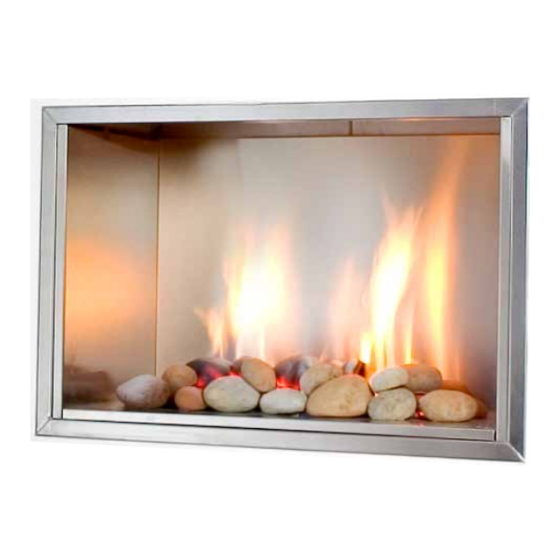
Page 24: Stone Configuration
STONE CONFIGURATION The Vision Vent Free Gas Fireplace can be operated with, or without, the decorative stones and/or embers. The following is the recommended stone/ember configuration. Slight differences in the placements are acceptable. When using the stones and embers, begin by placing one layer of the embers evenly over the entire burner top as shown in Figure 20. - Page 25 Figure 22 Next, place two large stones and three small stones on the burner as shown in Figure 22. Then place two medium and four small stones along the front edge of the burner as shown in Figure 23. Figure 23...
-
Page 26: Surrounds
SURROUNDS There are several surrounds for the Vision Vent Free Gas Fireplace. Ensure that the surround model is correct for the fireplace installation so the combustion air is not blocked. Attach the surround mounting brackets per the instructions included with the surround and hang the surround on the... -
Page 27: Operating Instructions
OPERATING INSTRUCTIONS FOR YOUR SAFETY READ BEFORE LIGHTING WARNING: If you do not follow these instructions exactly, a fire or explosion may result causing property damage, personal injury or loss of life. A. This appliance is equipped with an ignition device which automatically lights the pilot. Do not try to light the pilot by hand. - Page 28 TO TURN OFF THE HEATER 7. Push the OFF button on the remote control to turn the appliance off. RESETTING THE SYSTEM To reset the system: 1. press and hold the receiver reset button until you hear the second of two beeps then 2.
-
Page 29: Maintenance
MAINTENANCE A qualified service agency should conduct an annual inspection and maintenance of your Vision Vent Free Fireplace and the installation to keep it running safely. The following procedures should be performed only by a qualified service person. The gas supply should be turned off whenever a maintenance procedure is performed. -
Page 30: Troubleshooting
TROUBLESHOOTING OBSERVED PROBLEM: POSSIBLE CAUSE: REMEDY: A. No transmission (motor does not 1. Receiver must learn new code. 1. Reset system as above. turn) 2. No power. 2. Confirm power. 3. The receiver is surrounded by 3. Change the position of the antenna. metal, reducing the transmission range. - Page 31 OBSERVED PROBLEM: POSSIBLE CAUSE: REMEDY: D. No pilot flame and control 4. Over tightened thermocouple. 4. Replace valve and thermocouple inter- continues to spark rupter. 5. Receiver 5. Replace receiver and reprogram code as above. E. Pilot is lit and control continues 1.
-
Page 32: Parts List
Make a periodic visual inspection of the pilot and main burner flames. The flames should look similar to those in the picture above. VISION VENT FREE PARTS LIST Burner Module, NG V-VF-BM-NG-01 Pilot Assembly V-VF-PA-01 Stainless Liner Kit V-SLK-01 Small Stainless Surround... -
Page 33: Warranty
PRODUCT INSTALLATION RECORD Installer: Please complete this form. Customer: Please retain this information. Purchased From Date of Purchase Installed By Date of Installation Fireplace Serial Number Fuel Type... -
Page 34: Programming The Remote Control
Appendix A PROGRAMMING THE REMOTE CONTROL Note: The system shuts off the appliance completely if there is no change in the flame height for 5 days. Setting °C/24 Hour or °F/12 Hour Clock. Press OFF and SMALL FLAME to toggle between °F/12 hr and °C/24 hr clock. Setting the time. - Page 35 Appendix A Timer mode. The appliance must be in standby mode; pilot ignited. The Timer setting allows you to set 2 burner Temp times and 2 burner Temp times every 24 hrs. For Temp to operate as a thermostat, TEMP must be set at 4°C or higher. If the Temp setting is decreased to - -, the motor will turn the valve to the standby position in the moon times and await the next burner Temp cycle.
- Page 36 EUROPEAN HOME a division of Europa Ja, Inc. 376 Washington St. Suite 203 Malden, MA 02148 tel: 781/324-8383 fax: 781/324-8384 www.europeanhome.com rev.140409...
Need help?
Do you have a question about the VISION and is the answer not in the manual?
Questions and answers