
Related Manuals for DriSteem XTR


Summary of Contents for DriSteem XTR
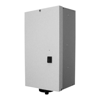
- Page 1 E l e c t r od e S t e a m Hu m i d i f i e r Installation, Operation, and Maintenance Manual...
- Page 2 ATTENTION INSTALLER W A R N I N G ! Read this manual before installing humidifier. This product must be installed by qualified HVAC and electrical contractors and in compliance with local, state, and federal codes. Leave manual with product owner. Improper installation may cause property damage, severe personal injury, or death as a result of electric shock, burns, and/or fire.
-
Page 3: Table Of Contents
Dispersion tube ........17 XTR steam blower ........18 Operation Principle of operation . -
Page 4: Specifications
Table 2-1: XTR humidifier specifications Maximum Maximum Current draw Shipping operating steam capacity (amps) weight weight Voltage lbs/hr kg/h Amps 120V 1.38 11.5 13.1 17.1 208V 2.39 11.5 13.1 17.1 240V 2.76 11.5 13.1 17.1 Figure 2-1: Table 2-2: XTR humidifier dimensions... -
Page 5: Choosing A Location
I m p o r t a n t : Choosing a location for the humidifier When selecting a location for the humidifier, consider the following: Install humidifier only in locations that meet the following temperature and relative Proximity to duct humidity (RH) requirements: Install the humidifier near the air duct system where the dispersion assembly will be located. -
Page 6: Mounting The Humidifier
Table 4-1: Figure 4-1: Mounting hole locations Mounting dimensions XTR humidifier Dimension inches 4.63 117.5 3.63 92.1 0.75 19.0 2.25 57.2 12.25 311.2 2.75 69.9 OM-7496 W A R N I N G ! Prepare humidifier for mounting Mount humidifier per the instructions in this manual and to a structurally stable surface. - Page 7 Secure cabinet in place using four screws. For finished space mounting with blower, locate stud for mounting XTR unit to wall. Use of anchors is acceptable for mounting blower in finished spaces. Always take care to avoid excess stress on the blower and humidifier when performing maintenance.
-
Page 8: Supply Water And Drain Piping
Figure 6-1: Field piping overview for XTR humidifier Steam vapor hose; may also use tubing or pipe. See Table 15-1 for maximum piping lengths. Tubing or pipe must be grounded. Fill valve (with screen) ¾" (DN20) metallic drain piping. If piping run is over 10' (3 m) increase pipe to 1¼"... - Page 9 I m p o r t a n t : Thoroughly flush the Supply water quality supply water piping to remove pipe residue XTR humidifiers use normal tap water to generate humidification and stagnant water before connecting steam. Water conductivity must be within the range of 125 to 1250 piping to the humidifier.
-
Page 10: Field Wiring
Humidifier field wiring W A R N I N G ! All wiring must be in accordance with all governing codes and Only qualified electrical personnel should with the unit wiring diagram. The unit wiring diagram is inside the perform field wiring installation procedures. cabinet door. - Page 11 Ground wire should be the same size as power wiring. Control input wiring XTR humidifiers accept RH signals from DRI-STEEM control components. For wiring connection requirements, first determine which control scenario applies. Then, refer to the corresponding control input wiring diagram shown on the following pages, or located inside the accessory box.
-
Page 12: Humidistat Placement
Vapor absorption high. This same condensation can take place in has taken place other areas in your home with the possibility of Point of vapor damage resulting. absorption Doorway Window DC-1084M mc_060508_0750-xtr... -
Page 13: Wiring Diagrams
Figure 11-1: Control wiring diagrams... - Page 14 Figure 12-1: Control wiring diagrams...
-
Page 15: Dispersion
I M P O R T A N T : Selecting the dispersion assembly location Failure to follow the recommendations in this section can result in excessive back the water vapor being discharged is carried off with the airstream pressures on the humidifier. This will result and is absorbed before it can cause condensation or dripping in in unacceptable humidification system the duct. -
Page 16: Interconnecting Piping Requirements
Connecting humidifier to dispersion assembly with vapor hose requirements for single tube applications. may use unacceptable release agents or material mixes that can affect humidifier system performance adversely. Using hose from alternative manufacturers increases the possibility of foaming in the steam cylinder. Foaming can cause water level control inaccuracies and reduced steam production. - Page 17 Connecting humidifier to dispersion assembly with tubing or pipe (continued) condensation. materials used to assemble the pipe. This will minimize the possibility of foaming in the steam cylinder. Denatured alcohol or mineral spirits work best for removing residual materials. use the recommend installation as shown on Page 16. Table 15-1: Maximum steam carrying capacity and length of interconnecting vapor hose, tubing, and pipe* †††...
-
Page 18: Drip Tee Installation
Install a drip tee as shown below when the humidifier is mounted higher than the dispersion assembly, when interconnecting hose or piping needs to go over an obstruction, or when interconnecting piping runs are long. IMPORTANT: Vapor hose must be supported to prevent sagging or low spots. -
Page 19: Dispersion Tube
Pitch* (diameter) Secure and seal duct 90° long sweep or escutcheon plate two 45° elbows XTR humidifier OM-7502 Table 17-1: Dispersion tube escutcheon plate dimensions for 7/8" tube Dimension Notes: inches * Pitch vapor hose, tubing or pipe toward humidifier: –... -
Page 20: Xtr Steam Blower
XTR steam blower XTR steam blower humidifier OM-7503 humidifier OM-7504 XTR steam blower The XTR steam blowers (XTRB), designed for use in finished spaces, disperse steam into large open spaces and are particularly useful where there are no air-handling ducts. - Page 21 Steam outlet As steam is discharged from the XTR steam blower (XTRB) it Figure 19-1: quickly cools and turns to a visible fog that is lighter than air. As XTR steam blower rise, spread, throw this fog is carried away from the XTRB by the airstream, it tends to Air intake grille rise toward the ceiling.
- Page 22 OM-7506 6.75 Mounting the XTR steam blower The XTR steam blower can be mounted directly on top of an XTR humidifier cabinet or remotely from the humidifier. Installation must comply with governing codes. Mount the steam blower so that it is plumb.
- Page 23 Provide at least 4" (102 mm) clearance on each side of the XTR steam blower for air intake. Low voltage field wiring is required to connect the XTR steam blower fan to the humidifier blower terminals.
- Page 24 Condensate hose W A R N I N G ! Make sure the XTR steam blower is installed plumb. If it is not installed Plastic tie plumb then standing water can accumulate in the steam blower, which can: Water seal 7"...
- Page 25 Wiring the XTR steam blower Power is provided to the XTR steam blower from the humidifier blower terminals. Connect leads from XTRB to terminals 7 and 8 on the XTR circuit board. Be sure to tighten terminals securely. Table 23-1:...
-
Page 26: Principle Of Operation
When the relative humidity level in the space being humidified drops below set point, the microprocessor controller in the XTR humidifier receives a call for humidity and calculates a corresponding amperage value. The controller closes the contactor, which energizes the electrodes. If there is no water or not enough water in the steam cylinder, the fill valve opens and water enters the steam cylinder. -
Page 27: End-Of-Season Drain
End-of-season drain Safety functions XTR humidifiers are protected against If there is no call for humidity for 72 hours, the humidifier is placed running dry — current does not flow when in End-of-Season (EOS) mode. When the unit enters EOS mode,... -
Page 28: Humidifier Start-Up
Steam capacity limitation The steam capacity can be limited by a potentiometer on the printed circuit board. The XTR humidifier is adjusted to operate at the nominal capacity (no limitation). The limitation can be adjusted down from 100% to as low as 25% of the maximum output. -
Page 29: System Messages
LED messages The humidifier is factory programmed to display five system messages using the LED. The LED messages indicate the following: Normal operation Check steam cylinder. This message can occur during start-up or after installing a new cylinder if the supply water has low conductivity. -
Page 30: Maintenance Procedures
Inspect unit every 500 hours of operation W A R N I N G ! At 500 hour intervals, inspect the steam cylinder, fill and drain When performing maintenance on the XTR valves, vapor hose, condensate piping, water supply piping, drain, humidifier: drain piping, and all other parts for proper operation and/or cleaning requirements. - Page 31 7. Remove the cylinder. 8. Check the drain valve. If the drain valve port is dirty, clean per the instructions on the next page. 9. Check O-ring. Ensure that the O-ring of the drain valve body is correctly placed. Change the O-ring if necessary. Dampen the O-ring seals before replacing cylinder.
- Page 32 1. Remove the steam cylinder. 2. Remove the three screws and washers securing the drain cup plate to the drain cup. 3. Disconnect the two slip-on terminals from the two tabs on the 24 VAC drain valve coil. 4. Remove the hose clamp and hose from the drain valve body. Take the drain valve assembly to a sink for disassembly and cleaning.
-
Page 33: Troubleshooting
1. Review possible causes and recommended actions. If you have a problem with your XTR humidifier, review the troubleshooting guide on the following pages for possible causes and recommended actions for typical problems. 2. If you’re still having problems, call us. - Page 34 Table 32-1: Problem/possible cause/action Problem Possible cause Action No LED display No power or incorrect voltage to processor board Humidifier does not Non-existent supply voltage energize; steam cylinder to humidifier does not heat up Non-existent control voltage Control terminals are open. proving switch, etc.
- Page 35 Table 33-1: Problem/possible cause/action Problem Possible cause Action Fill valve does not close. Malfunctioning level control system . Add sodium bicarbonate only to increase. Consult DRI-STEEM for further advice. Fill valve is stuck. needed. Drain valve is open. * Check for corrosion/pitting on the drain valve plunger. Consult DRI-STEEM if present. Fill valve cycles on and Malfunctioning level control .
- Page 36 Table 34-1: Problem/possible cause/action Problem Possible cause Action Humidity above set Improperly located point humidistat Reduced airflow Malfunctioning controls Unit oversized High entering relative humidity Hunting (humidity Malfunctioning control swings above and below system desired set point) manual. Noisy operation Fill/drain valve noise slamming sound as fill valve closes is "water hammer"...
-
Page 37: Replacement Parts
Figure 35-1: XTR humidifier replacement parts OM-7510... - Page 38 Hoses, adaptors, and clamps Inlet Hose, steam 22/29 mm 530002 Fill adapter assembly, 3/8" XT unit 180994-038 Hose clamp, steam hose to XTR dispersion 700560-075 Fill adapter, 3/8" O.D. tubing 530001-002 Hose, drain 22/29 mm × 10.00 530005-010 Washer, 5/8" hose...
- Page 39 Figure 37-1: XTR dispersion replacement parts OM-7511 Table 37-1: XTR dispersion replacement parts Description Part no. Dispersion, XTR assembly 162728-001 DRI-STEEM Model XTRB steam blower 412016-101 Bracket, XTRB Remote Blower Mount 530001-061 Hose, condensate 6/10 mm 530004...
-
Page 40: Two-Year Limited Warranty
DRI-STEEM’s election. visit our Web site: www.dristeem.com DRI-STEEM shall not be liable for any costs or expenses, whether direct or indirect, associated with the installation, removal or reinstallation of any defective product.
Need help?
Do you have a question about the XTR and is the answer not in the manual?
Questions and answers