Jacobsen R-311T Maintenance Manual
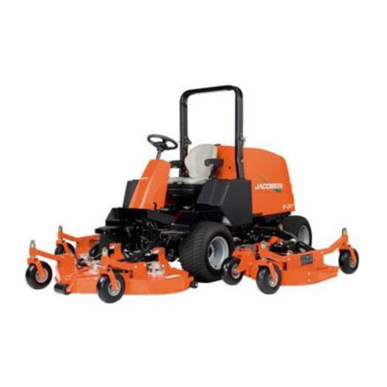
Rotary mower with folding rops
Hide thumbs
Also See for R-311T:
- Parts & maintenance manual (182 pages) ,
- Technical/repair manual (48 pages) ,
- Dealer's manual (48 pages)
Table of Contents
Advertisement
Quick Links
Parts & Maintenance
Manual
R-311T
™
Rotary Mower with folding ROPS
69171 – Kubota
If incorrectly used, this machine can cause severe injury. Those who use
and maintain this machine should be trained in its proper use, warned of its
dangers, and should read the entire manual before attempting to set up,
operate, adjust, or service the machine.
GB
®
V2403-M-T
WARNING
4227700-Rev A
6
5
9
1 1
1 6
1 5
1 3
7
8
1 8
1 7
1 - I N C L U D E S I T E M S 3 - 1 6
1 9
3
4
1 0
When Performance Matters.
™
Advertisement
Chapters
Table of Contents

Subscribe to Our Youtube Channel
Related Manuals for Jacobsen R-311T


Summary of Contents for Jacobsen R-311T
- Page 1 4227700-Rev A 1 - I N C L U D E S I T E M S 3 - 1 6 Parts & Maintenance Manual R-311T ™ Rotary Mower with folding ROPS ® 69171 – Kubota V2403-M-T WARNING If incorrectly used, this machine can cause severe injury. Those who use...
-
Page 2: Service Parts
Suggested Stocking Guide To Keep your Equipment fully operational and productive, Jacobsen suggests you maintain a stock of the more commonly used maintenance items. We have included part numbers for additional support materials and training aids. To order any of the following material: 3. -
Page 3: Table Of Contents
Table of Contents Safety Troubleshooting Operating Safety ..........4 General .............. 29 Important Safety Notes .........5 Maintenance & Lubrication Charts Specifications General .............. 30 Product Identification..........6 Lubrication Chart ..........30 Engine ..............6 Maintenance Charts ...........31 Mower ..............6 Parts List Cutting Units ............7 How To Use The Parts Catalog ...... -
Page 4: Operating Safety
Only accessories 20. Operate the machine up and down the face of slopes attachments approved by Jacobsen. (vertically), not across the face (horizontally). 7. Stay alert for holes in the terrain and other hidden 21. To prevent tipping or loss of control, do not start or hazards. -
Page 5: Safety
Adjustments and maintenance should always be performed by a qualified technician. If additional information or service is needed, contact your Authorized Jacobsen Dealer who is kept informed of the latest methods to service this equipment and can provide prompt and efficient service. -
Page 6: Specifications
SPECIFICATIONS SPECIFICATIONS PRODUCT IDENTIFICATION _________________________________________________ 69171......R-311T with folding ROPS. ® 11524 WILMAR BLVD, CHARLOTTE, NC 28273 A Textron Company Serial Number ....An identification plate, like the one 1-800-848-1636 (US) PRODUCT OF U.S.A. shown, listing the serial number, is 1792 41.7... -
Page 7: Cutting Units
ACCESSORIES AND SUPPORT LITERATURE __________________________________ Contact your area Jacobsen Dealer for a complete listing of accessories and attachments. CAUTION Use of other than Jacobsen authorized parts and accessories may cause personal injury or damage to the equipment. Accessories Support Literature Air Blow Gun ............ -
Page 8: Declaration Of Conformity
Valmistajan toiminimi ja täydellinen osoite ▪ Nom commercial et adresse complète du fabricant ▪ Firmenname und vollständige Adresse des Herstellers ▪ Jacobsen, A Textron Company Επωνυμία και ταχυδρομική διεύθυνση κατασκευαστή ▪ A gyártó üzleti neve és teljes címe ▪ Ragione sociale e indirizzo completo del fabbricante ▪... - Page 9 Plaats en datum van de verklaring ▪ Deklaratsiooni väljastamise koht ja kuupäev ▪ Vakuutuksen paikka ja päivämäärä ▪ Lieu et date de la déclaration ▪ Jacobsen, A Textron Company Ort und Datum der Erklärung ▪ Τόπος και ημερομηνία δήλωσης ▪ A nyilatkozat kelte (hely és idő) ▪ Luogo e data della dichiarazione ▪...
-
Page 10: Adjustments
1. Adjustments and maintenance should always be performed by a qualified technician. If proper adjustment cannot be made, contact an authorized Jacobsen Dealer. BALL JOINTS_____________________________________________________________ When adjusting ball joints, be sure cut-out in ball joint is parallel to the mounting bracket, then secure in place. -
Page 11: Brake Pedal
ADJUSTMENTS BRAKE PEDAL ____________________________________________________________ Adjust brakes after replacing or servicing brake engage parking brake. Brake must prevent mower assembly, or if pedal travel becomes excessive. from rolling. Adjust as required. 1. When installing new brake pads, burnish pads by driving mower at mowing speed while applying a slight pressure on brake pedal for about 5 seconds. -
Page 12: Cruise Control Switch
(T) and the traction pedal in Neutral and close when pedal is moved in the forward direction. 3. Secure switch adjustment and test operation. 4. If adjustment cannot be made, contact your authorized Jacobsen Dealer. Figure 3G... -
Page 13: Neutral Switch
2. With traction pedal in Neutral, adjust switch (B) so pedal linkage screw (C) is centered over switch target. 3. Secure switch adjustment and test operation. 4. If adjustment cannot be made, contact your authorized Jacobsen Dealer. Switch Target Figure 3H 3.10 HYDRO NEUTRAL _________________________________________________________ If the mower “creeps”... -
Page 14: Steering Toe In
ADJUSTMENTS 3.11 STEERING TOE IN _________________________________________________________ “Toe in” should be adjusted from X + 1/16 in. (1.5 mm). 1. Turn wheels to straight ahead position. 2. Loosen tie rod jam nuts (U). 3. Adjust tie rod and retighten jam nuts. 4. -
Page 15: Cutting Height
ADJUSTMENTS 3.14 CUTTING HEIGHT _________________________________________________________ Level the front mower before setting the cutting height for 2. Figure 3M shows the height adjustment decal for the first time. Do not remove the cutting units from the the casters. mower to change cutting height. Column 1 - Height of Cut Column 2 - Arrangement of Spacers Cutting height for decks can be adjusted from 1 to 5-1/2... -
Page 16: Leveling Front Mower
ADJUSTMENTS 3.15 LEVELING FRONT MOWER _________________________________________________ 1. Before leveling the front deck, the mower tires, and caster wheels must be properly inflated. The cutting height is directly related to the radius of the tire. 2. Set the cutting height of the front mower to 5-1/2 in. (140 mm). -
Page 17: Servicing Front Deck
ADJUSTMENTS 3.17 SERVICING FRONT DECK___________________________________________________ The front deck can be raised and tilted up to improve To return deck to service: access to the cutting unit and blades for service and 1. Start engine and fully raise front deck. Stop engine. cleaning. -
Page 18: Torque Specification
All torque values included in these charts are approximate and are for reference only. Use of these torque values is at your sole risk. Jacobsen is not responsible for any loss, claim, or damage arising from the use of these charts. -
Page 19: Maintenance
4. Use the illustrations in the Parts Catalog as adjustments cannot be made, contact an Authorized reference for the disassembly and reassembly of Jacobsen Dealer. components. 2. Inspect the equipment on a regular basis, establish 5. Recycle or dispose of all hazardous materials a maintenance schedule and keep detailed records. -
Page 20: Sharpening Blades
MAINTENANCE SHARPENING BLADES_____________________________________________________ 1. Place a wooden block between the blade and mower housing to stop the blade from moving. To remove blade, turn screw holding blade counterclockwise Maximum WARNING 1/2” (13 mm) The mower blades can develop sharp edges. Use caution whenever servicing and handling. -
Page 21: Engine
The warning horn will sound when the temperature During the break-in period, Jacobsen recommends the reaches 230° F (110° C). To prevent damage to the following: engine, never allow the engine to operate above 230° F. -
Page 22: Air Filter
MAINTENANCE AIR FILTER_______________________________________________________________ Do not remove the element for inspection or 3. Assemble the new element and make sure it seats cleaning. Unnecessary removal of the filter increases properly. the risk of injecting dust and other impurities into the 4. Reassemble cap making sure it seals completely engine. -
Page 23: Battery
MAINTENANCE BATTERY ________________________________________________________________ Make absolutely certain the ignition switch is OFF and 1. When installing the battery, always assemble the RED, positive (+) battery cable first and the ground, the key has been removed before servicing the battery. BLACK, negative (-) cable last. 2. -
Page 24: Hydraulic Hoses
To change hydraulic oil: 4. After oil has drained install drain plug and fill with 1. Clean the area around the oil cap to prevent Jacobsen Hydraulic oil. impurities from entering and contaminating the 5. Purge air from system. system. -
Page 25: Hydraulic Oil Filters
If the Interlock System does not function properly and the problem cannot be corrected contact an CAUTION authorized Jacobsen Dealer. Always turn the ignition switch off and remove the 3. Keep the wire harness and all individual wires away negative battery cable (Black) before inspecting or from moving parts to prevent damage. -
Page 26: Wheel Mounting Procedure
Do not wash any portion of the equipment while it is cleaners. hot or with engine running. Do not use high pressure Repair damaged metal surfaces and use Jacobsen spray or steam. Use cold water and automotive touch-up paint. Wax the equipment for maximum paint cleaners. -
Page 27: Radiator And Oil Cooler
1. Check coolant level daily. Radiator should be full and once a month, or add more than one quart at a recovery bottle should be up to the cold mark. time, have a authorized Jacobsen Dealer check the cooling system. 2. Drain and refill annually. Remove the radiator cap, open the engine block drain and the radiator drain. -
Page 28: Storage
MAINTENANCE 4.22 STORAGE________________________________________________________________ General Cutting Units 1. Wash the mower thoroughly and lubricate. Repair 1. Wash the cutting units thoroughly, then repair and and paint damaged or exposed metal. paint any damaged or exposed metal. 2. Inspect the mower, tighten all hardware, replace 2. -
Page 29: Troubleshooting
TROUBLESHOOTING TROUBLESHOOTING GENERAL ________________________________________________________________ The troubleshooting chart below lists basic problems that may occur during start-up and operation. For more detailed information regarding the hydraulic and electrical systems contact your area Jacobsen Dealer. Symptoms Possible Causes Action Engine will not start. -
Page 30: Maintenance & Lubrication Charts
MAINTENANCE & LUBRICATION CHARTS MAINTENANCE & LUBRICATION CHARTS GENERAL________________________________________________________________ 2. Lubricate with grease that meets or exceeds NLGI Grade 2 LB specifications. Apply grease with a WARNING manual grease gun and fill slowly until grease begins to seep out. Do not use compressed air guns. Before you clean, adjust, or repair this equipment disengage all drives, lower implements to the ground, 3. -
Page 31: Maintenance Charts
* Indicates initial service for new machines. ** Or every two years whichever comes first. III - Use Jacobsen hydraulic fluid: Capacity: 5 gallons (19 Liters). Order Part No. 2500548 carton, containing *** Inspect visible hoses and tubes for leaks or oil marks. -
Page 32: Parts List
Transportation 4. Order by the quantity desired, the part number, and charges must be prepaid. description of the part as given in the parts list. Use of other than Jacobsen authorized parts will void the warranty. -
Page 33: Table Of Contents
PARTS LIST TABLE OF CONTENTS______________________________________________________ 1.1 ..Decals ..............34 56.2..Electrical Schematic ........144 2.1 ..Hood and Front Cowling ........36 57.1..Hydraulic Schematic........148 3.1 ..Hood..............38 58.1..O-Ring Chart............ 150 4.1 ..Floorboard Platform ......... 40 5.1 .. -
Page 34: Decals
R-311T Serial No. All 1.1 Decals THIS RADIATOR CONTAINS ANTI-FREEZE PROTECTED TO -26 F (-32 C) Mix equal parts of clean water and a premium quality ethylene glycol based anti-freeze to 4181861 maintain the boil over, rust and corrosion protection. - Page 35 Located on right frame rail 4181865 Decal, Warning 366608 Decal, Wing Transport Lock Cable 4192000 Decal, Weight Transfer 4211460 Decal, R-311T 4187680 Decal, Left Side Stripe 4187681 Decal, RIght Side Stripe 4181863 Decal, See Manual for Maintenance Located on Charge Filter Bracket...
-
Page 36: Hood And Front Cowling
R-311T Serial No. All 2.1 Hood and Front Cowling 33 / 34... - Page 37 R-311T Item Part No. Qty. Description Serial Numbers/Notes 4266310 Hood, R-311 See 3.1 4212423 Latch, Overcenter • Keeper 400408 Screw, 1/2-13 x 1-1/2” Hex Head 450152 Screw, M5-0.8 x 20 mm Hex Head 403912 Screw, #10-24 x 5/8” Truss Head 450322 Nut, M5-0.8 Hex...
-
Page 38: Hood
R-311T Serial No. All 3.1 Hood 7 / 8 ®... - Page 39 • Screw, 1/4-20 x 1” Slotted 453023 • Flat Washer, 1/4 446130 • Lockwasher, 1/4 Heavy 443102 • Nut, 1/4-20 Hex 4187680 • Decal, Left Side Jacobsen 4187681 • Decal, RIght Side Jacobsen 4211460 • Decal, R-311T 453009 • Flat Washer, 5/16 446134 •...
-
Page 40: Floorboard Platform
R-311T Serial No. All 4.1 Floorboard Platform 23 21... - Page 41 R-311T Item Part No. Qty. Description Serial Numbers/Notes 4185961 Right Side Fender 4208122 Left Side Fender 4185981 Pad, Right Side Step 4185980 Pad, Left Side Step 441614 Carriage Bolt, 5/16-18 x 1” 445781 Nut, 5/16-18 Whizlock Flange 441669 Carriage Bolt, 1/4-20 x 2-3/4”...
-
Page 42: Utility Box
R-311T Serial No. All 5.1 Utility Box 30 14... - Page 43 R-311T Item Part No. Qty. Description Serial Numbers/Notes 4208120 Utility Box 4208121 • Plate, Support 400188 • Screw, 5/16-18 x 1” Hex Head 453009 • Flat Washer, 5/16 473211 • Washer, Neoprene 446134 • Lockwasher, 5/16 443106 • Nut, 5/16-18 Hex...
-
Page 44: Console Support
R-311T Serial No. All 6.1 Console Support 15 14... - Page 45 R-311T Item Part No. Qty. Description Serial Numbers/Notes 4168044 Support, Console 4227180 Console Wall Seat and Seat Base See 7.1 4185864 Rod, Seat Pivot 821164 Hair Pin, 1/16 x 1-1/4 x 1/4” 452007 Flat Washer, 3/8 400264 Screw, 3/8-16 x 1-1/4” Hex Head...
-
Page 46: Seat And Seat Base
R-311T Serial No. All 7.1 Seat and Seat Base 4239123 4181865... - Page 47 R-311T Item Part No. Qty. Description Serial Numbers/Notes 450453 Locknut, M8-1.25 Center 452388 4 Screw, M8-1.25 x 20 mm Hex Head 4185860 4 Seat Riser 400186 4 Screw, 5/16-18 x 7/8” Hex Head 4198581 3 Spacer 445795 Nut, 5/16-18 Spiralock Flange...
-
Page 48: Control Panel
R-311T Serial No. All 8.1 Control Panel Part of 8 Part of 11 Part of 34 Part of 19 Control Panel Decal... - Page 49 R-311T Item Part No. Qty. Description Serial Numbers/Notes 4193340 Control Panel 4170760 • Decal, Control Panel 338601 Circuit Breaker, 10 Amp REFERENCE CB1, See 56.1 338601 Circuit Breaker, 10 Amp REFERENCE CB2, See 56.1 338601 Circuit Breaker, 10 Amp REFERENCE CB3, See 56.1...
-
Page 50: Lift Valve
R-311T Serial No. All 9.1 Lift Valve Item Part No. Qty. Description Serial Numbers/Notes 1001802 Lift Valve See 48.1 366150 Weather Strip 132473 Right Wing Lift Lever 132472 Center Lift Lever 132471 Left Wing Lift Lever 366522 Knob, Lift Lever... -
Page 51: Throttle
R-311T Serial No. All 10.1 Throttle Item Part No. Qty. Description Serial Numbers/Notes 4172944 Throttle Handle 326731 Knob, Throttle 4177920 Cable, Throttle See 22.1 for Engine Connection 445800 Palnut, 3/16 440116 Carriage Bolt, 3/8-16 x 7/8” 4178004 Bracket, Throttle Lever Mounting... -
Page 52: Traction Pedal Linkage
R-311T Serial No. All 11.1 Traction Pedal Linkage... - Page 53 R-311T Item Part No. Qty. Description Serial Numbers/Notes 4116048 Pedal, Hydro 3007230 Stop, Mow Speed 3003474 Grip, Reverse Pedal 3003475 Grip, Forward Pedal 400188 Screw, 5/16-18 x 1” Hex Head 3002695 Flat Washer, 5/16 444718 Locknut, 5/16-18 Center 4235466 Arm, Pedal 409812 Screw, 5/16-18 x 3/4”...
-
Page 54: Traction Linkage
R-311T Serial No. All 12.1 Traction Linkage 19 8... - Page 55 R-311T Item Part No. Qty. Description Serial Numbers/Notes 2500257 Tube, Traction Return 3007095 Stop, Rear Pivot 3000593 Spacer, Traction Control 358795 Screw, 3/8-24 x 5-1/2” Special 358794 Washer 364970 Spring, Compression 443812 Nut, 3/8-24 Hex Jam 446142 Lockwasher, 3/8 Heavy...
-
Page 56: Brake Pedal
R-311T Serial No. All 13.1 Brake Pedal... - Page 57 R-311T Item Part No. Qty. Description Serial Numbers/Notes 4183261 Brake Pedal 352726 • Bushing 3006327 Shaft, Brake Pedal 4100460 Arm, Brake 403770 Screw, 5/16-18 x 3/4” Hex Flange 4251410 Lever, Parking Brake 400190 Screw, 5/16-18 x 1-1/4 Hex Head 453009...
-
Page 58: Brake Caliper
R-311T Serial No. All 14.1 Brake Caliper... - Page 59 R-311T Item Part No. Qty. Description Serial Numbers/Notes 446142 Lockwasher, 3/8 Heavy 443110 Nut, 3/8-16 Hex 4215701 Plate, Caliper Mounting 400411 Screw, 1/2-13 x 1-3/4” Hex Head Grade 8 4212780 Hardened Washer, 1/2” 446154 Lockwasher, 1/2 Heavy 4134825 Screw, 1/2-13 x 1-1/4” Hex Head...
-
Page 60: Frame And Front Axle
R-311T Serial No. All 15.1 Frame and Front Axle 9 / 10... - Page 61 R-311T Item Part No. Qty. Description Serial Numbers/Notes 4223140 Front Axle 4207700 4213320 Hub, Wheel 4212741 Disc, Brake 442423 Screw, 1/4-20 x 5/8” Torx Flat Head 557624 460093 Cotter Pin, 1/8 x 2-1/2” 453030 Flat Washer, 1-1/8” 4213264 Bracket, Right Side Return Spring...
-
Page 62: Steering Axle
R-311T Serial No. All 16.1 Steering Axle 22 23 21 22... - Page 63 R-311T Item Part No. Qty. Description Serial Numbers/Notes 2720313 Steering Axle 2720298 • Bushing, Axle Pivot 3010489 • Bushing, Mount Pivot 4121827 Screw, 1/2-20 x 1-3/4” Socket Head 443820 Nut, 1/2-20 Hex Jam 471221 Grease Fitting, 90° 361648 Washer, Thrust...
-
Page 64: Steering Tower
R-311T Serial No. 69171 - 1651 ~ 2197 17.1 Steering Tower ®... - Page 65 Washer, Steering Wheel 2811364 Steering Wheel 2811365 • Cover, Steering Wheel 447224 Lockwasher, 5/8 Internal Tooth 4182386 Decal, Jacobsen Emblem 5002918 Gas Spring 5002919 Cable, Actuator 416911 Screw, #10-24 x 1/2” Thread Cutting 400216 Screw, 5/16-18 x 2-3/4” Hex Head 400192 Screw, 5/16-18 x 1-1/2”...
-
Page 66: Steering Tower
R-311T Serial No. 69171 - 2198 and Up 17.2 Steering Tower ®... - Page 67 Cover, Steering Tower 404016 Screw, 1/4-20 x 5/8” Truss Head 445245 Tinnerman Nut 441677 Carriage Bolt, 5/16-18 x 1-1/2” 4182386 Decal, Jacobsen Emblem 132523 Valve, Weight Transfer 555862 • Cartridge, Valve 5003579 • Seal Kit 400120 Screw, 1/4-20 x 2” Hex Head...
-
Page 68: Air Cleaner
R-311T Serial No. All 18.1 Air Cleaner 4199140 4205183 22 23... - Page 69 R-311T Item Part No. Qty. Description Serial Numbers/Notes 4227441 Air Cleaner Includes Decal 4133818 • Cover, Air Cleaner 4133820 • Filter, Primary Air Cleaner 4133821 • Filter, Safety Air Cleaner 5003373 • Vactuator Valve 4128084 Clamp, Air Cleaner Mounting 400184 Screw, 5/16-18 x 3/4”...
-
Page 70: Radiator And Oil Cooler
R-311T Serial No. All 19.1 Radiator and Oil Cooler THIS RADIATOR CONTAINS ANTI-FREEZE PROTECTED TO -26 F (-32 C) Mix equal parts of clean water and a premium quality ethylene glycol based anti-freeze to maintain the boil over, rust and corrosion protection. - Page 71 R-311T Item Part No. Qty. Description Serial Numbers/Notes 4227440 Radiator Shroud 4164381 • Decal, Danger 400264 Screw, 3/8-16 x 1-1/4” Hex Head 452006 Flat Washer, 5/16 446142 Lockwasher, 3/8 Heavy 4227420 Radiator and Hydraulic Oil Cooler Includes Decals 550863 • Radiator Cap 363995 •...
-
Page 72: Engine
R-311T Serial No. All 20.1 Engine... - Page 73 R-311T Item Part No. Qty. Description Serial Numbers/Notes 4196741 Engine, Kubota V2403-M-T-E3B For complete listing of engine service parts, See Engine Parts 4113986 • Engine Oil Filter Manual 557619 • Cartridge, Fuel Filter 5000938 • Alternator REFERENCE U1, See 56.1 556988 •...
-
Page 74: Engine Mounts
R-311T Serial No. All 21.1 Engine Mounts... - Page 75 R-311T Item Part No. Qty. Description Serial Numbers/Notes 4207484 Mount, Rear Engine 358794 Washer 4207482 Mount, Left Front Engine 4207483 Mount, Right Front Engine 365979 Screw, M12-1.25 x 25 mm Metric Grade 8.8 446154 Lockwasher, 1/2 Heavy 453017 Flat Washer, 1/2 362263 Screw, M10-1.25 x 25 mm...
-
Page 76: Engine Fuel Control
R-311T Serial No. All 22.1 Engine Fuel Control Item Part No. Qty. Description Serial Numbers/Notes 4177920 Throttle Cable See 10.1 400108 Screw, 1/4-20 x 3/4” Hex Head 453023 Flat Washer, 1/4 444708 Locknut, 1/4-20 Center > Change from previous revision... -
Page 77: Muffler
R-311T 23.1 Muffler Item Part No. Qty. Description Serial Numbers/Notes 4196900 Muffler 4263130 Exhaust Pipe 553020 Gasket, Exhaust Included with Engine 363586 Screw, M8-1.25 x 20 mm Hex Head 1000050 Muffler Bracket 400188 Screw, 5/16-18 x 1” Hex Head 452006... -
Page 78: Fuel Tank
R-311T Serial No. All 24.1 Fuel Tank Part of Hood To Engine Return To Engine 21 28... - Page 79 R-311T Item Part No. Qty. Description Serial Numbers/Notes 163987 Fuel Cap 163986 Fuel Sender REFERENCE U8, See 56.1 148081 • Gasket 403910 Screw, #10-24 x 1/2” Truss Head 361117 Bushing, Fuel 452006 Flat Washer, 5/16 400188 Screw, 5/16-18 x 1” Hex Head...
-
Page 80: Hydraulic Tank Support
R-311T Serial No. All 25.1 Hydraulic Tank Support... - Page 81 R-311T Item Part No. Qty. Description Serial Numbers/Notes 4175121 Support, Rear Tank 132432 Support, Left Side Tank 132431 Support, Right Side Tank 400286 Screw, 3/8-16 x 2-3/4” 446142 Lockwasher, 3/8 Heavy 445806 Nut, 3/8-16 Hex Nylock 400262 Screw, 3/8-16 x 1” Hex Head...
-
Page 82: Hydraulic Tank
R-311T Serial No. All 26.1 Hydraulic Tank... - Page 83 R-311T Item Part No. Qty. Description Serial Numbers/Notes 4227460 Hydraulic Oil Tank Includes Decals 4211081 Valve, Oil Drain 3002397 Plug, Magnetic 367551 Switch, Hydraulic Oil Temperature REFERENCE SW13, See 56.1 ★ 163915 Breather, Tank ★ 557680 • Screen Important note located below ★...
-
Page 84: Pumps And Control Valve
R-311T Serial No. 69151 - 1651 ~ 2060 27.1 Pumps and Control Valve 19 18... - Page 85 R-311T Item Part No. Qty. Description Serial Numbers/Notes 4153880 Pump, Traction See 51.1 557447 • O-Ring 338938 • Pump Coupler 4138342 Pump, 4 Section Gear 4138341 • Seal Kit 557417 • Pump Adapter 557418 • Gasket 400412 Screw, 1/2-13 x 2” Hex Head...
-
Page 86: Pumps And Control Valve
R-311T Serial No. 69171 - 2061 and Up 27.2 Pumps and Control Valve 18 19 27 24... - Page 87 R-311T Item Part No. Qty. Description Serial Numbers/Notes 4153880 Pump, Traction See 51.1 557447 • O-Ring 338938 • Pump Coupler 4260990 Pump, 4 Section Gear 4138341 • Seal Kit 4260890 Flange, Adapter 557447 O-Ring 400412 Screw, 1/2-13 x 2” Hex Head...
-
Page 88: Traction Hydraulics
R-311T Serial No. All 28.1 Traction Hydraulics 11 11... - Page 89 R-311T Item Part No. Qty. Description Serial Numbers/Notes 4153880 Traction Pump See 27.1 or 27.2 340269 Tee, 10-12-12 Straight Run 339911 • O-Ring, -10 ORFS 339912 • O-Ring, -12 ORFS 339900 • O-Ring, -12 ORB 132417 Hose, Traction Pump to Axle Motor 340074 Fitting, -12ORFS x -12 ORB 90°...
-
Page 90: Motor Drain Hydraulics
R-311T Serial No. All 29.1 Motor Drain Hydraulics... - Page 91 R-311T Item Part No. Qty. Description Serial Numbers/Notes 4170780 Front Axle Motor See 27.1 or 27.2 351109 Fitting, -6 37° Flare x -6 ORB Straight 339897 • O-Ring, -6 ORB 4173220 Hose, Axle Motor to Traction Pump 4173200 1 Tee, -6 37° Flare x -8 ORB Branch Run 339898 •...
-
Page 92: Gear Pump Hydraulics
R-311T Serial No. All 30.1 Gear Pump Hydraulics... - Page 93 R-311T Item Part No. Qty. Description Serial Numbers/Notes 4227460 Hydraulic Oil Tank See 26.1 365959 Strainer, 100 Mesh Screen 2812075 • O-Ring 338946 Fitting, -24 ORB x 1-1/2” Hose 90° 339903 • O-Ring 326112 Clamp, Hose 4148898 Hose, Pump Suction...
-
Page 94: Return Hydraulics
R-311T Serial No. All 31.1 Return Hydraulics... - Page 95 R-311T Item Part No. Qty. Description Serial Numbers/Notes 4135582 Valve, Deck Control See 27.1 or 27.2 340070 Fitting, -10 ORFS x -10 ORB 90° 339911 • O-Ring, -10 ORFS 339899 • O-Ring, -10 ORB 4192440 Hose, Front to Left Wing Deck Valve...
-
Page 96: Steering And Charge Hydraulics
R-311T Serial No. All 32.1 Steering and Charge Hydraulics To Control To Charge Filter Valve (Hose Item 11) (Hose Item 3) To Steering Cylinder (Hose Item 5) To Steering Cylinder (Hose Item 6) - Page 97 R-311T Item Part No. Qty. Description Serial Numbers/Notes 4174300 Valve, Main Control See 27.1 or 27.2 339984 Fitting, -8 ORFS x -8 ORB Straight 339910 • O-Ring, -8 ORFS 339898 • O-Ring, -8 ORB 4185401 Hose, Control Valve to Steering...
-
Page 98: Lift Hydraulics
R-311T Serial No. All 33.1 Lift Hydraulics Part of Frame... - Page 99 R-311T Item Part No. Qty. Description Serial Numbers/Notes 4174300 Valve, Main Control See 27.1 or 27.2 340066 Fitting, -8 ORFS x -8 ORB 90° 339910 • O-Ring, -8 ORFS 339898 • O-Ring, -8 ORB 123222 Tube, Control Valve to Lift Valve...
-
Page 100: Lift Hydraulics (Continued)
R-311T 33.1 Lift Hydraulics (Continued) Part of Frame... - Page 101 R-311T Item Part No. Qty. Description Serial Numbers/Notes 339961 Nut, 11/16-16 Bulkhead Hex 4193300 Hose, Tee to Tee 366437 Bracket, Bulkhead See 39.1 132583 Hose, Tee to Tank 351127 Fitting, -8 37° Flare x 3/8 NPT Straight 4188043 Hose, Lift to Backpressure Valve 351108 Fitting, -8 37°...
-
Page 102: Deck Hydraulics
R-311T Serial No. All 34.1 Deck Hydraulics... - Page 103 R-311T Item Part No. Qty. Description Serial Numbers/Notes 4135582 Valve, Front Deck Control See 27.1 or 27.2 4202340 Adapter, 10-8 Reducer Union 339899 • O-Ring, -10 ORB 339898 • O-Ring, -8 ORB 4202120 Check Valve 4201921 • Body, Check Valve 4201920 •...
-
Page 104: Hydraulic Clamping
R-311T Serial No. All 35.1 Hydraulic Clamping Steering Cylinder Hoses Part of floorboard Front Axle Motor Hoses... - Page 105 R-311T Item Part No. Qty. Description Serial Numbers/Notes 366607 Spacer, Hose 359860 Clamp, 2 Hose 400204 Screw, 5/16-18 x 3-1/2” 446136 Lockwasher, 5/16 Heavy 443106 Nut, 5/16-18 Hex 3008793 Clamp, Hose Front Deck Motor Hoses 3008792 Spacer, Plate 400210 Screw, 5/16-18 x 5” Hex Head...
-
Page 106: Electrical Components
R-311T Serial No. All 36.1 Electrical Components Part of Left Wing Part of Right Wing Limit Switch Harness Limit Switch Harness Part of Console K18 K19 Harness Relay Identification To Starter Post To Glow Plugs Glow Plug Solenoid Wiring... - Page 107 R-311T Item Part No. Qty. Description Serial Numbers/Notes 4210661 Wire, Solenoid to Glow Plug 4210660 Wire, Circuit Breaker to Solenoid 4210662 Wire, Starter to Circuit Breaker 443102 Nut, 1/4-20 Hex REFERENCE K5, K17, K18, K19, 4193880 Relay SPDT K20, K21, See 56.1...
-
Page 108: Electrical Routing
R-311T Serial No. All 37.1 Electrical Routing Engine Tractor Harness Harness... - Page 109 R-311T Item Part No. Qty. Description Serial Numbers/Notes 4167640 Cable Tie, Fir Tree Remote Terminal to Starter. 4211620 Positive Remote Terminal Cable See 4.1 for Terminal 365980 Screw, M12-1.25 x 20 mm 446154 Lockwasher, 1/2 Heavy 446130 Lockwasher, 1/4 Heavy...
-
Page 110: Harness
R-311T Serial No. All 38.1 Harness... - Page 111 R-311T Item Part No. Qty. Description Serial Numbers/Notes 4218120 Wire Harness, Console 554492 • Lockwasher, Size 24 554493 • Panel Nut, Size 24 555845 • Light Bulb 555846 • Diode 555847 • Light Strip 4211640 Wire Harness, Engine 4201161 Wire Harness, Mower...
-
Page 112: Front Lift Arms
R-311T Serial No. All 39.1 Front Lift Arms... - Page 113 R-311T Item Part No. Qty. Description Serial Numbers/Notes 2720206 Right Front Lift Arm 342033 • Bushing 2720207 Left Front Lift Arm 342033 • Bushing 4184641 Shaft, Lift Arm Pivot 346091 Pin, Retaining 446136 Lockwasher, 5/16 Heavy 400184 Screw, 5/16-18 x 3/4” Hex Head...
-
Page 114: Wing Lift Arms
R-311T Serial No. All 40.1 Wing Lift Arms Right Wing Shown 1 / 3 2 / 4 6 30 2 / 4... - Page 115 R-311T Item Part No. Qty. Description Serial Numbers/Notes 4222365 Right Wing Arm 2720298 • Bushing 4222366 Left Wing Arm (Not Shown) 2720298 • Bushing 2248004 Shaft, Pivot Arm 64251-001 Flat Washer, M5 446136 Lockwasher, 5/16 Heavy 400184 Screw, 5/16-18 x 3/4” Hex Head...
-
Page 116: Wing Deck Latch
R-311T Serial No. All 41.1 Wing Deck Latch 13 33 18 / 19... - Page 117 R-311T Item Part No. Qty. Description Serial Numbers/Notes 446136 Lockwasher, 5/16 Heavy 443106 Nut, 5/16-18 Hex 453011 Flat Washer, 3/8 446142 Lockwasher, 3/8 Heavy 445806 Nut, 3/8-16 Hex 400272 Screw, 3/8-16 x 2-1/4” Hex Head 132601 Bracket, Deck Roller 400264 Screw, 3/8-16 x 1-1/4”...
-
Page 118: Deck Mounting
R-311T Serial No. All 42.1 Deck Mounting... - Page 119 R-311T Item Part No. Qty. Description Serial Numbers/Notes 64173-02 Pin, Snap RIng 3000439 Clevis Pin, 1/2 x 3-3/4” 3000487 Clevis Pin, 5/8 x 3” 346913 Spacer 460050 Cotter Pin, 3/16 x 1-1/4” 3006300 Clevis Pin, 5/8 x 3-5/16” 362464 Wheel Bolt, 7/16-20...
-
Page 120: Front Deck
R-311T Serial No. All 43.1 Front Deck "X" "X" 5 / 7 8 / 10 38 13 24 25 NO STEP... - Page 121 R-311T Item Part No. Qty. Description Serial Numbers/Notes 4212580 Front Deck 4164381 • Decal, Blade Contact Danger 3002676 • Decal, Cutting Height 366609 • Decal, No Step 2721180 Motor, Deck Counter-Clockwise Rotation 557523 • Key 4186581 Blade, Couter-Clockwise Rotation 2721181...
-
Page 122: Wing Deck
R-311T Serial No. All 44.1 Wing Deck Left Wing Deck Shown (Right Opposite) 8 / 10 5 / 7 1 / 2 Left Wing Deck 42 / 43 5 / 7 8 / 10 Right Wing Deck "X" "X"... - Page 123 R-311T Item Part No. Qty. Description Serial Numbers/Notes 4212600 Left Wing Deck Includes Items 3 and 4 4212601 Right WIng Deck (Not Shown) 4164381 • Decal, Blade Contact Danger 3002676 • Decal, Cutting Height 2721180 Motor, CCW Rotation Deck Outside motor on Right Deck 557523 •...
-
Page 124: Caster Wheels
R-311T Serial No. All 45.1 Caster Wheels 2 / 17 2 / 17 2 / 17 2 / 17... - Page 125 R-311T Item Part No. Qty. Description Serial Numbers/Notes 131717 Yoke, Caster Wheel Spindle 453022 Flat Washer, 3/4 x 1/8 Thick 3003207 Shaft, Caster Wheel 460056 Cotter Pin, 3/16 x 2” 403578 Screw, #10-24 x 1” Hex Head 446118 Lockwasher, #10...
-
Page 126: Deck Bumper
R-311T Serial No. All 46.1 Deck Bumper Item Part No. Qty. Description Serial Numbers/Notes 3003427 Bracket, Deck Bumper 400262 Screw, 3/8-16 x 1” Hex Head 453011 Flat Washer, 3/8 446142 Lockwasher, 3/8 Heavy 445806 Nut, 3/8-16 Hex Nylock 361723 Stop, Rubber... -
Page 127: Deck Valve
R-311T Serial No. All 47.1 Deck Valve Part Number 4135582 4 / 5/ 6 Item Part No. Qty. Description Serial Numbers/Notes 5002911 Relief Valve 5003579 • Seal Kit 5002912 Relief Valve 5003554 • Seal Kit 3010199 Plug, SAE #6 339897 •... -
Page 128: Lift Valve
R-311T Serial No. All 48.1 Lift Valve Part Number 1001802... - Page 129 R-311T Item Part No. Qty. Description Serial Numbers/Notes 558005 Plug 500745 Plug 4113978 Spring ● Poppet 500746 Seat 5001599 Plunger 5001603 Plunger 558004 558007 Retaining Ring Seat 558011 Spacer 5001616 Spring 4113979 Bushing ● O-Ring 5001614 Spring 5001615 Poppet 5001612 Detent Repair Kit •...
-
Page 130: Control Valve
R-311T Serial No. All 49.1 Control Valve Part Number 4174300 Viewed from Top Viewed from Rear Viewed from Right Viewed from Front Viewed from Left Item Part No. Qty. Description Serial Numbers/Notes 5003510 Relief Valve, 200 psi 5003579 • Seal Kit 556845 Flow Control Valve, 4.5 GPM... -
Page 131: 4Wd Valve
R-311T Serial No. All 50.1 4WD Valve Part Number 4135555 3, 5 Viewed from Right Viewed from Left Viewed from Top Viewed from Bottom Item Part No. Qty. Description Serial Numbers/Notes 556897 Spool Valve 5003581 • Seal Kit 558038 Check Valve 5003581 •... -
Page 132: Traction Pump
R-311T Serial No. All 51.1 Traction Pump Part Number 4153880... - Page 133 R-311T Item Part No. Qty. Description Serial Numbers/Notes 557454 Dowel Pin ● Retaining Ring ● Retaining Ring 4162501 Screw, Cap 557444 Plug 557442 Rotating Kit 4162502 Plate, Control Arm Cover 4162503 • Seal, Control Arm Shaft ● O-Ring 4162504 Washer...
-
Page 134: Rear Wheel Motor
R-311T Serial No. All 52.1 Rear Wheel Motor Serial No. All Part Number 4178560 Item Part No. Qty. Description Serial Numbers/Notes ● Seal Exclusion ● Seal, 3” I.D. ▼ Back-Up Ring ▼ Shaft Seal 5003384 Shaft and Bearing Kit 554780 554779 ●... -
Page 135: Rops
R-311T 53.1 ROPS Item Part No. Qty. Description Serial Numbers/Notes 4179004 ROPS • Upper ROPS • Right Lower ROPS • Left Upper ROPS 4193120 • Tube, Polyurethane 4192460 • Pull Pin Assembly 800788 • Screw, 1/2-120 x 2-1/4” Hex Head 446152 •... -
Page 136: Seat
R-311T Serial No. All 54.1 Seat Part Number 4185878... - Page 137 R-311T Item Part No. Qty. Description Serial Numbers/Notes 4200240 Backrest Cushion 4200241 Seat Cushion 4173562 Lumbar Handle Kit 4173563 Wear Parts Kit, Backrest Attatchment 4200244 Cover, Left Side 4200245 Cover, Right Side 4173566 OPS Switch Kit 4173567 Left Side Adjustable Armrest Kit...
-
Page 138: Front Axle
R-311T Serial No. All 55.1 Front Axle Part Number 4223140 Shim Thickness Item 0.010 0.011 0.012 0.013 0.014 0.015 0.016 0.017 0.018 10 4213621-1 4213621-2 4213621-3 4213621-4 4213621-5 4213621-6 4213621-7 4213621-8 4213621-9 Shim Thickness (Continued) Item 0.019 0.020 0.021 0.022 0.023... - Page 139 R-311T Item Part No. Qty. Description Serial Numbers/Notes 4201300 Case Assembly, Differential (T/L) 4201320 Gear and Pinion Assembly, Hypoid 4201520 Screw, Gear Drive 4220820 Carrier Sub Assembly Includes bearing caps and screws 4201580-1 Shim, 0.003 Thick Adjustment 4201580-2 Shim, 0.005 Thick Adjustment 4201580-3 Shim, 0.010 Thick Adjustment...
-
Page 140: Electrical Schematic
R-311T Serial No. 1651 ~ 2081 56.1 Electrical Schematic Og/Bu Wh/Rd Pk/Bu Gn/Wh Gn/Wh Gn/Wh Gn/Wh Pk/Bu Gn/Wh Pk/Bu Pk/Bu Rd/Wh Rd/Wh Rd/Wh Rd/Bn Bn/Rd Og/Bk Bn/Rd Rd/Wh Rd/Wh SW10 Og/Bk Rd/Wh Rd/LB Gn/Wh Pu/Ye Pu/Ye Wh/Bn Rd/Bu Wh/Bk Pu/Wh... - Page 141 R-311T Og/Bu Og/Bu Tn/Rd Tn/Rd Wh/Bk SW20 Tn/Rd Og/Bu SW18 Bu/Wh Wh/Bk Bu/Wh Gn/Wh Gn/Wh SW11 Pk/Bu Pk/Bu Wh/Bk Off - None Bn/Rd Bn/Rd On - B+I+A; X+Y SW12 Start - B+I+S Gn/Wh Wh/Bk Gn/Wh Wh/Gn Bn/Rd Gn/Wh Og/Bk SW13...
- Page 142 R-311T Reference Part Item Description Serial Numbers/Notes Illustration Number See 4.1 Battery See 8.1 338601 10 Amp Circuit Breaker (Interlock) See 8.1 338601 10 Amp Circuit Breaker (Instruments) See 8.1 338601 10 Amp Circuit Breaker (Cruise, 4WD) See 8.1 338558 30 Amp Circuit Breaker (Accessories) See 8.1...
- Page 143 R-311T Reference Part Item Description Serial Numbers/Notes Illustration Number Not Shown 555845 Water Temp Warning Light Not Shown 555845 Low Engine Oil Pressure Warning Light Not Shown 555845 Left Turn Light Optional Tail Light Optional Head Light Included in Kit 69128...
- Page 144 R-311T Serial No. 69171 - 2082 and Up 56.2 Electrical Schematic Og/Bu Wh/Rd Pk/Bu Gn/Wh Gn/Wh Gn/Wh Gn/Wh Pk/Bu Gn/Wh Pk/Bu Pk/Bu Rd/Wh Rd/Wh Rd/Wh Rd/Bn Bn/Rd Og/Bk Bn/Rd Rd/Wh Rd/Wh SW10 Og/Bk Rd/Wh Rd/LB Gn/Wh Pu/Ye Pu/Ye Wh/Bn Rd/Bu...
- Page 145 R-311T Og/Bu Og/Bu Tn/Rd Tn/Rd Wh/Bk SW20 Tn/Rd Og/Bu SW18 Bu/Wh Wh/Bk Bu/Wh Gn/Wh Gn/Wh SW11 Pk/Bu Pk/Bu Wh/Bk Off - None Bn/Rd Bn/Rd On - B+I+A; X+Y SW12 Start - B+I+S Gn/Wh Wh/Bk Gn/Wh Wh/Gn Bn/Rd Gn/Wh Og/Bk SW13...
- Page 146 R-311T Reference Part Item Description Serial Numbers/Notes Illustration Number See 4.1 Battery See 8.1 338601 10 Amp Circuit Breaker (Interlock) See 8.1 338601 10 Amp Circuit Breaker (Instruments) See 8.1 338601 10 Amp Circuit Breaker (Cruise, 4WD) See 8.1 338558 30 Amp Circuit Breaker (Accessories) See 8.1...
- Page 147 R-311T Reference Part Item Description Serial Numbers/Notes Illustration Number Not Shown 555845 Low Charge Pressure Warning Light Not Shown 555845 Water Temp Warning Light Not Shown 555845 Low Engine Oil Pressure Warning Light Not Shown 555845 Left Turn Light Optional...
- Page 148 R-311T Serial No. All 57.1 Hydraulic Schematic Four Section Gear Pump Traction Pump 2.48 3500 PSI Front Axle 1.04 1.04 1.04 0.77 5.04 2800 RPM Motor CCW Rotation 3500 PSI Outside Right Wing Motor Right Wing Deck Valve 1.04 .0669...
- Page 149 R-311T Valve Right Motor 11.9 11.9 Left Steering Motor Valve 1500 PSI Control Valve DL SW 200 PSI Steering Cylinder 1500 PSI Backpressure Valve 50 PSI 300 PSI 300 PSI 300 PSI Lift Valve 0.0595 in. 0.0595 in. 0.0595 in.
- Page 150 R-311T Serial No. All 58.1 O-Ring Chart O-Ring Face O-Ring Boss O-Ring Face O-Ring Face O-Ring Boss O-Ring Boss Seal Size Dash Size Seal Size Seal Size Dash Size Dash Size W-X-Y W-X-Y W-X-Y O-Ring Face O-Ring Not O-Ring Face...
- Page 151 R-311T Adapter Part Dash Adapter Type (W) O-Ring (X) O-Ring (Y) O-Ring (Z) O-Ring Number. Size 339979 Straight Adapter 339909 339897 339983 Straight Adapter 339910 339897 339984 Straight Adapter 339910 339898 339989 10-10 Straight Adapter 339911 339899 340003 Straight Adapter...
-
Page 152: Fluids And Compounds
See your local Jacobsen Dealer * Refer to the Parts & Maintenance manual for the correct hydraulic oil requirements for your machine. Jacobsen offers a High Usage Parts Catalog illustrating commonly used Parts through easy to read line Drawings. See your local Jacobsen... - Page 153 INDEX 1000050...... 77 162236 ....... 77 3001374 ...... 49 326731 ......51 1000588...... 49 162479 ....... 71 3001386 ...... 49 337229 ......69 1000649....53 162716 ..... 119 3001409 ...... 83 338558 ......49 1000700....89 162721 ....... 49 3001523 ..85 338601 ......49 1001311......
- Page 154 INDEX 345671 ....107 364830 ....61 367461 ..... 121 401226 ....... 63 346091 ....113 364883 ......69 367465 ....... 65 402006 ....... 69 346294 ......119 364945 ....89 367551 ....73 402066 ....... 53 346913 ......119 364970 ......55 367601 ..... 119 402118 .....
- Page 155 INDEX 4133821...... 69 4173300 ...... 85 4188043 ....101 4200251 ....137 4134270...... 73 4173562 ....137 4188620 ....101 4200253 ....137 4134320...... 73 4173563 ....137 4188780 ...... 37 4200254 ....137 4134383...... 73 4173566 ....47 4189009 ...... 37 4200255 ....137 4134530....
- Page 156 INDEX 4203610.....139 4213280.......59 4235460 ...... 53 443126 ..... 135 4203611.....139 4213300.......61 4235466 ...... 53 443806 ....... 57 4203612.....139 4213301.......59 4236000 ...... 53 443808 ..... 107 4203613.....139 4213320.......61 4236862 ...... 99 443810 ....43 4203614.....139 4213480..57 4238825 ...... 87 443812 ....55 4203615.....139 4213621-1....138 4239123 ....
- Page 157 INDEX ... 121 460014 ....57 503095 ....... 63 557771 ......57 460032 ....... 63 503553 ..... 115 558004 ......129 446148 ....... 73 460050 ..... 119 503626 ....... 79 558005 ......129 446152 ..... 135 460052 ..... 113 522516 ....... 37 558007 ......129 446154 ..
- Page 158 Equipment from Jacobsen is built to exacting standards ensured by ISO 9001 and ISO 14001 registration at all of our manufacturing locations. A worldwide dealer network and factory trained technicians backed by Genuine Jacobsen Parts provide reliable, high-quality product support.
Need help?
Do you have a question about the R-311T and is the answer not in the manual?
Questions and answers