Sign In
Upload
Manuals
Brands
Tripp Lite Manuals
UPS
SmartOnline SU60K
Tripp Lite SmartOnline SU60K Manuals
Manuals and User Guides for Tripp Lite SmartOnline SU60K. We have
3
Tripp Lite SmartOnline SU60K manuals available for free PDF download: Owner's Manual, Manual, Specification
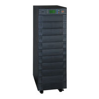
Tripp Lite SmartOnline SU60K Owner's Manual (156 pages)
3-Phase UPS Systems
Brand:
Tripp Lite
| Category:
UPS
| Size: 32.85 MB
Table of Contents
English
2
Table of Contents
2
Introduction
3
Important Safety Instructions
4
Save These Instructions
4
Control Panel Features
6
Front and Rear Panel Features
7
Cabinet Installation
9
Unpacking
9
Placement
10
Internal Battery Connection
11
7-6 Câblage du Boîtier Externe de la Batterie
11
Internal Battery Wiring Diagrams
11
Internal Battery Connection Procedure
13
7 Wiring
16
Wiring Warnings
16
Wiring Preparation
16
UPS System Terminal Block Diagram
17
7-4 External Battery Cabinet Wiring Diagrams
17
Electrical and Cable Data
18
External Battery Cabinet Wiring
19
AC Input/Output Wiring (Single UPS)
20
AC Input/Output Wiring (Parallel UPS – Single Input)
21
Operating Modes
22
Online (Normal) Mode (Single UPS)
22
Battery Backup Mode (Single UPS)
22
8-3 Auto Bypass Mode (Single UPS)
22
Manual Bypass Mode (Single UPS)
22
Online Mode (Parallel UPS)
23
Battery Backup Mode (Parallel UPS)
23
8-7 Auto Bypass Mode (Parallel UPS)
23
Manual Bypass Mode (Parallel UPS)
24
Start-Up, Shutdown and Bypass
25
Control Panel and Breaker Diagrams
25
Preliminary Checklist (Single UPS)
25
Normal Start-Up Procedure (Single UPS)
25
Battery Start-Up Procedure (Single UPS)
26
Manual Bypass Procedure (Single UPS)
27
Shutdown Procedure (Single UPS)
27
Preliminary Checklist (Parallel UPS)
28
Start-Up Procedure (Parallel UPS)
28
Shutdown Procedure (Parallel UPS)
29
Manual Bypass Procedure (Parallel UPS)
30
Switching from Manual Bypass to Normal (Parallel UPS)
31
Display and Confi Guration
32
Control Panel Diagram
32
Display Hierarchy
32
Default Display
33
Status Messages and Diagrams
33
Main Menu
35
UPS System "Measure" Menu
35
UPS System Setup Menu
36
Bypass Setup Menu
36
Output Setup Menu
37
Battery Setup Menu
38
Local Setup Menu
40
Maintenance Menu
41
Statistics Menu
42
Event Log Menu
43
Manual Setup & Test Menu
44
Firmware Upgrade Menu
45
Other Menu Choices
45
Communications
46
11-1 Communications Interfaces
46
SNMPWEBCARD Slot
46
11-3 Input Dry Contact Interface
46
Remote Emergency Power off (EPO) Circuit Diagram
47
Auxiliary Dry Contact Input Circuit Diagram
47
External Battery Cabinet Temperature Inputs
47
External Battery Status Input
47
Output Dry Contact Interface Detail
48
Output Dry Contact Circuit Diagram
49
Serial Port Circuit Diagram
50
Parallel Redundancy Port
50
Specifi Cations
51
UPS System Technical Specifi Cations
51
UPS System Floor Loading Table
51
Battery Pack Floor Loading Table
51
Storage and Service
52
Español
53
English
53
Español
54
Français
54
Introducción
55
Instrucciones de Seguridad Importantes
56
3 Características y Funciones
58
Características y Funciones
58
Del Panel Frontal y Trasero
59
Instalación del Gabinete
61
Preparación
61
Colocación
62
Conexión de la Batería Interna
63
(Únicamente SU40K) Diagramas de Cableado de la Batería Interna
63
Procedimiento de Conexión de la Batería Interna
65
Cableado
68
Advertencias sobre el Cableado
68
7-2 Preparación del Cableado
68
Diagrama del Bloque de Terminal del Sistema UPS
69
Diagramas del Cableado del Gabinete de Baterías Externas
69
Información Eléctrica y Cables
70
Cableado del Gabinete de Baterías Externas
71
Cableado de Entrada/Salida CA (un solo UPS)
72
Cableado de Entrada/Salida CA (UPS en Paralelo -Una Entrada)
73
Modos de Operación
74
8-1 Modo en Línea (Normal) (un solo UPS)
74
Modo en Respaldo (un solo UPS)
74
Modo en Derivación Automática (un solo UPS)
74
8-5 Modo en Línea (UPS en Paralelo)
75
Modo en Respaldo (UPS en Paralelo)
75
Modo en Derivación Automática (UPS en Paralelo)
75
Modo en Derivación Manual (UPS en Paralelo)
76
Arranque, Apagado y Derivación
77
Diagramas del Panel de Control E Interruptor de Circuitos
77
Lista de Control Preliminar (un solo UPS)
77
Procedimiento de Arranque Normal (un solo UPS)
77
Procedimiento de Arranque con la Batería (un solo UPS)
78
Procedimiento de Derivación Manual (un solo UPS)
79
Procedimiento de Apagado (un solo UPS)
79
Procedimiento de Arranque (UPS en Paralelo)
80
Procedimiento de Apagado (UPS en Paralelo)
81
Procedimiento de Derivación Manual (UPS en Paralelo)
82
13 9-11 Cambiando de Derivación Manual a Normal (UPS en Paralelo)
83
Pantalla y Confi Guración
84
Diagrama del Panel de Control
84
Mensajes de Estado y Diagramas
85
Menú Principal
87
Menú de Instalación de la Derivación
88
Menú de Instalación del Sistema UPS
88
Menú de Instalación de la Salida
89
Menú de Instalación de la Batería
90
Menú de Instalación Local
92
Menú de Mantenimiento
93
Menú de Estadísticas
94
Menú de Registro de Eventos
95
Menú de Instalación Manual y Prueba
96
Comunicaciones
98
11-2 Ranura SNMPWEBCARD
98
11-3 Interfaz de Entrada de Contacto Seco
98
Interfaces de Comunicaciones
98
11-8 Detalle de la Interfaz de Salida de Contacto Seco
100
11-10 Diagrama de Circuito del Puerto Serial
102
Especifi Caciones
103
Especifi Caciones Técnicas del Sistema UPS
103
13 Almaceneaje y Servicio
104
Garantía
104
Français
106
English
106
14 Garantía
106
Introduction
107
Instructions Importantes Concernant
108
Caractéristiques du Tableau de Commande
110
Fonctionnalités des Panneaux Avant
111
Déballage du Produit
113
Installation du Boîtier
113
Préparation
113
Mise en Place
114
Connexion de la Batterie Interne
115
6-1 Schémas de Câblage de la Batterie Interne
115
Procédure de Connexion de la Batterie Interne
117
7-2 Préparation du Câblage
120
Avertissements Concernant Le Câblage
120
Schéma du Bornier de L'onduleur
121
Schémas de Câblage du Boîtier Externe de la Batterie
121
Données Électriques Et de Câblage
122
Câblage Entrée/Sortie CA (Onduleur Unique)
124
Câblage Entrée/Sortie CA (Onduleur Parallèle - Entrée Unique)
125
Câblage
120
Modes de Fonctionnement
126
Mode Batterie de Secours (Onduleur Unique)
126
Mode Dérivation Automatique(Onduleur Unique)
126
Mode Dérivation Manuel (Onduleur Unique)
126
Mode en Ligne (Normal) (Onduleur Unique)
126
Mode Batterie de Secours (Onduleur Parallèle)
127
Mode en Ligne (Onduleur Parallèle)
127
Mode Dérivation Automatique( Onduleur Parallèle)
128
Mode Dérivation Manuelle (Onduleur Parallèle)
128
Démarrage, Arrêt Et Dérivation
129
Liste de Contrôle Préliminaire (Onduleur Unique)
129
Procédure de Démarrage Normal (Onduleur Unique)
129
Schémas du Tableau de Commande Et du Coupe-Circuit
129
Procédure de Démarrage Sur Batterie (Onduleur Unique)
130
Procédure D'arrêt (Onduleur Unique)
131
Procédure de Dérivation Manuelle (Onduleur Unique)
131
Liste de Contrôle Préliminaire (Onduleur Parallèle)
132
Procédure de Démarrage (Onduleur Parallèle)
132
Procédure D'arrêt (Onduleur Parallèle)
133
Procédure de Dérivation Manuelle (Onduleur Parallèle)
134
Affi Chage Et Confi Guration
136
Schéma du Tableau de Commande
136
Hiérarchie D'affi Chage
136
Affi Chage Par Défaut
137
Messages Et Diagrammes D'état
137
Menu Principal
139
Menu de Mesures de L'onduleur
139
Menu de Confi Guration de L'onduleur
140
Menu de Confi Guration du Mode Dérivation
140
Menu de Confi Guration de Sortie
141
Menu de Confi Guration de la Batterie
142
Menu de Confi Guration Locale
144
Menu D'entretien
145
Menu des Statistiques
146
Menu du Journal des ÉVénements
147
Menu de Confi Guration Manuelle Et Tests
148
Autres Choix de Menu
149
Communications
150
Menu de Mise À Niveau du Micrologiciel
149
Fente SNMPWEBCARD
150
Interface D'entrée À Contact Sec
150
Interfaces de Communication
150
Entrée D'état de la Batterie Externe
151
Entrées de Température du Boîtier de la Batterie Externe
151
Schéma du Circuit Auxiliaire D'entrée À Contact Sec
151
Schéma du Circuit de L'interrupteur D'urgence À Distance
151
Détail de L'interface de Sortie À Contact Sec
152
Schéma du Circuit de Sortie À Contact Sec
153
Port Parallèle Avec Redondance
154
SpéCIfi Cations
155
RS 232 Schéma du Circuit du Port Série
154
SpéCIfi Cations Techniques de L'onduleur
155
Tableau de la Charge Sur Le Plancher de L'onduleur
155
Tableau de la Charge Sur Le Plancher du Bloc-Batterie
155
Entreposage Et Entretien
156
Garantie
156
Advertisement
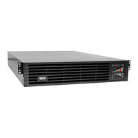
Tripp Lite SmartOnline SU60K Manual (110 pages)
3-Phase UPS Hardware Introduction and Troubleshooting SU Series
Brand:
Tripp Lite
| Category:
UPS
| Size: 27.38 MB
Table of Contents
Table of Contents
2
1 Basic Operation
3
Technical Specifi Cations
3
KX Models
3
K and KTV Models
4
SU80K Model
5
Features
6
Advanced Features
6
Control Panel Features
6
Front and Rear Panel Features
7
Operating Principles
13
System Layout
13
Internal Battery Layout
13
Power Module Layout
14
Opening and Closing the Unit
14
Operating Modes
15
Online (Normal) Mode (Single UPS)
15
Battery Backup Mode (Single UPS)
15
Auto Bypass Mode (Single UPS)
15
Manual Bypass Mode (Single UPS)
15
Online Mode (Parallel UPS)
16
Battery Backup Mode (Parallel UPS)
16
Auto Bypass Mode (Parallel UPS)
16
Manual Bypass Mode (Parallel UPS)
17
Hot Standby Mode (Parallel UPS)
17
Start-Up, Shutdown and Bypass
18
Control Panel and Breaker Diagrams
18
Preliminary Checklist (Single UPS)
18
Standard Start-Up Procedure (Single UPS)
18
Battery Start-Up Procedure (Single UPS)
19
Manual Bypass Procedure (Single UPS)
20
Shutdown Procedure (Single UPS)
20
Preliminary Checklist (Parallel UPS)
21
Start-Up Procedure (Parallel UPS)
21
Shutdown Procedure (Parallel UPS)
22
Manual Bypass Procedure (Parallel UPS)
23
Switching from Manual Bypass to Normal Mode (Parallel UPS)
24
Printed Circuit Boards (PCB)
25
PCB Location (System)
26
KX Models
26
K Models
28
PCB Power Module
31
Block and Wiring Diagrams
32
KX Models
32
2 Theory of Operation
33
DC Auxiliary Power Circuit
33
Auxiliary Power Failure Detection
33
Output Current Detection
34
Input Voltage Detection
35
Output Voltage Detection
36
Battery Voltage Detection
37
Bypass SCR Short-Circuit Detection
38
Bypass SCR Driver
39
Watchdog for System MCU
40
LCD Panel Control Circuit
41
Fan Control Circuit
42
Bypass SCR Temperature Detection
43
Communication Circuit for RS232
43
Communication Circuit for Slots
44
Communication Circuit for Output Dry Contact
45
Communication Circuit for Input Dry Contact and REPO
46
External Battery Cabinet Temperature Detection
47
Detection Circuit for Manual Bypass Switch
48
Detection Circuit for Output Breaker
48
Control Circuit for Power Module
49
Transformer over Temperature Detection
53
3 Communication
54
RS232 Port
54
Emergency Power off (EPO)
54
Setting EEPROM on the NH-M Board
56
Polling and Updating EEPROM
56
Calibrating EEPROM Gain
57
Setting Output Dry Contact Status
58
Upgrading Firmware for the System Board
59
Upgrading Firmware for the Power Module
64
Downloading the Event Log
72
4 Internal Battery
73
Installing and Removing Internal Batteries
74
Battery Cabinet
77
5 Troubleshooting
80
Alarm Messages
80
Troubleshooting Flow Charts
82
Main Volt/Freq Nok
82
Main Sequence Nok
83
Bypass Volt/Freq Nok
84
Bypass Sequence Nok
85
Bypass Static Switch over Temperature
85
Bypass Static Switch Fault
86
Bypass Static Switch Overload
86
Ups Internal Comm Abnormal
87
Battery Test Fail
88
Battery over Charge
88
Battery Bad
89
Bypass Fan Failure
90
Transformer Overheat
91
Ps Output Volt Nok
92
Ps Ext Parallel Comm Abnormal
93
Parallel Failure
94
Redundancy Loss
95
6 Power Module
96
Failure Power Module Identify
96
Power Module Replacement
99
7 Preventive Maintenance
103
Safety Overview
103
Suggested Tools and Supplies
103
UPS Procedure
103
Internal Battery Procedure
104
Appendix A Service Equipment and Tools
105
Appendix B Torque Table
106
Appendix C PCB and Test Point
110
Tripp Lite SmartOnline SU60K Specification (6 pages)
SmartOnline 60kVA Modular 3-Phase UPS System, On-line Double-Conversion UPS for North America
Brand:
Tripp Lite
| Category:
UPS
| Size: 0.13 MB
Table of Contents
Specifications
2
Voltage Regulation
3
Special Features
5
Warranty
5
Related Items
5
Advertisement
Advertisement
Related Products
Tripp Lite SmartOnline SU60KX
Tripp Lite SmartOnline SU60KTV
Tripp Lite SmartOnline SU6000RT3UHV
Tripp Lite SmartOnline SU6000RT3U
Tripp Lite SmartOnline SU6000RT3UXR
Tripp Lite SmartOnline SU6000RT4U
Tripp Lite SmartOnline SU6000RT4UHV
Tripp Lite SmartOnline SU6000RT4UHVHW
Tripp Lite SmartOnline SU6000RT4UHVG
Tripp Lite SmartOnline SU6000RT4UTFHW
Tripp Lite Categories
UPS
Cables and connectors
Switch
Network Cable
Surge Protector
More Tripp Lite Manuals
Login
Sign In
OR
Sign in with Facebook
Sign in with Google
Upload manual
Upload from disk
Upload from URL