Sign In
Upload
Manuals
Brands
SMC Networks Manuals
Extender
7724M/VSW - annexe 1
SMC Networks 7724M/VSW - annexe 1 Manuals
Manuals and User Guides for SMC Networks 7724M/VSW - annexe 1. We have
2
SMC Networks 7724M/VSW - annexe 1 manuals available for free PDF download: Manual, Installation Manual
SMC Networks 7724M/VSW - annexe 1 Manual (387 pages)
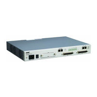
Extended Ethernet switch
Brand:
SMC Networks
| Category:
Network Router
| Size: 9.53 MB
Table of Contents
Table of Contents
5
1 Introduction
20
Audience
20
Document Structure
20
Tab. 1.1 Overview of Chapters
20
Document Convention
21
Document Notation
21
Tab. 1.2 Command Notation of Guide Book
21
Virus Protection
22
CE Declaration of Conformity
22
2 System Overview
23
Fig. 2.1 the Front View of Switch
23
System Features
24
3 Command Line Interface (CLI)
26
Configuration Mode
26
Privileged EXEC View Mode
27
Privileged EXEC Enable Mode
27
Tab. 3.1 Main Command of Privileged EXEC View Mode
27
Tab. 3.2 Main Command of Privileged EXEC Enable Mode
27
Global Configuration Mode
28
Bridge Configuration Mode
28
Tab. 3.3 Main Command of Global Configuration Mode
28
DHCP Pool Configuration Mode
29
DHCP Option Configuration Mode
29
Tab. 3.4 Main Command of Bridge Configuration Mode
29
Tab. 3.5 Main Command of DHCP Pool Configuration Mode
29
DHCP Option 82 Configuration Mode
30
Interface Configuration Mode
30
Tab. 3.6 Main Command of DHCP Option Configuration Mode
30
Tab. 3.7 Main Command of DHCP Option 82 Configuration Mode
30
Rule Configuration Mode
31
RMON Configuration Mode
31
Tab. 3.8 Main Command of Interface Configuration Mode
31
Tab. 3.9 the Commands of Rule Configuration Mode
31
Configuration Mode Overview
32
Fig. 3.1 Overview of Configuration Mode
32
Tab. 3.10 Main Command of RMON Configuration Mode
32
Useful Tips
33
Listing Available Command
33
Calling Command History
35
Exit Current Command Mode
36
Using Abbreviation
36
Using Command of Privileged EXEC Enable Mode
36
Tab. 3.11 Command Abbreviation
36
4 System Connection and IP Address
37
System Connection
37
Connecting to the Console Port
37
System Login
37
Password for Privileged EXEC Enable Mode
38
Changing Login Password
39
Login Password Recovery Process
40
Management for System Account
41
Creating System Account
41
Security Level
41
Limiting Number of Users
44
Auto Log-Out
45
Telnet Access
45
System Rebooting
46
Manual System Rebooting
46
Auto System Rebooting
47
System Authentication
48
Authentication Method
48
Authentication Interface
48
Primary Authentication Method
48
RADIUS Server
49
Frequency of Retransmit
49
RADIUS Server for System Authentication
49
RADIUS Server Priority
49
Timeout of Authentication Request
49
TACACS+ Server
50
Additional TACACS+ Configuration
50
TACACS+ Server for System Authentication
50
TACACS+ Server Priority
50
Timeout of Authentication Request
50
Accounting Mode
51
Displaying System Authentication
51
Configuring Interface
52
Enabling Interface
52
Assigning IP Address to Network Interface
53
Static Route and Default Gateway
53
Interface Description
54
Displaying Interface
55
Secure Shell (SSH)
56
SSH Server
56
Disconnecting SSH Client
56
Displaying On-Line SSH Client
56
Enabling SSH Server
56
Assigning Specific Authentication Key
57
Displaying Connection History of SSH Client
57
SSH Client
57
File Copy
57
Login to SSH Server
57
Authentication Key
58
Authentication
59
Fig. 4.1 Process of 802.1X Authentication
59
Authentication
60
Enabling 802.1X
60
RADIUS Server
60
Fig. 4.2 Multiple Authentication Servers
60
Authentication Mode
61
Authentication Port
62
Force Authorization
62
Interval for Retransmitting Request/Identity Packet
62
Number of Requests to RADIUS Server
62
Interval of Request to RADIUS Server
63
802.1X Re-Authentication
63
Enabling 802.1X Re-Authentication
63
802.1X Re-Authentication
64
Interval of Re-Authentication
64
Interval of Requesting Re-Authentication
64
Initializing Authentication Status
65
Displaying 802.1X Configuration
65
Restoring Default Value
65
User Authentication Statistics
65
Sample Configuration
66
5 Port Configuration
68
Port Basic
68
Ethernet Port Configuration
68
Enabling Ethernet Port
68
Auto-Negotiation
68
Transmit Rate
69
Duplex Mode
70
Flow Control
71
Port Description
71
Traffic Statistics
72
Packet Statistics
72
CPU Statistics
73
Protocol Statistics
74
Port Information
75
VDSL Port Configuration
76
Modulation of VDSL Signal
76
DMT Modulation
76
Fig. 5.1 Transmission in DSL System
76
Configuring VDSL Port
77
Fig. 5.2 DMT Modulation
77
Displaying Status of VDSL Port
78
Enabling VDSL Port
78
Tab. 5.1 Information Displayed by Command, Show Lre
78
Profile of VDSL Port
79
Tab. 5.2
79
Tab. 5.2 Profile of VDSL Port
79
Controlling Power According to Connection Distance
80
Tab. 5.3 Option Band of VDSL Port
80
Tab. 5.4 Value of PBO-Length
82
PSD Level
84
Tab. 5.5 the Frequency of PSD Level Per Band
84
PSD Mask Level
85
Interleave
85
Tab. 5.6 the Value of PSD Mask Level
85
Impulse Noise Protection
87
Trellis Coded Modulation (TCM)
87
Ham-Band
88
SNR Margin
89
Tab. 5.7 Bandwidth of Ham Band Frequency
89
Fig. 5.3 Deciding Transmit Rate According to SNR Margin
90
Bitloading Per Tone
91
G.handshake Tone
92
VDSL Checking Errors of VDSL Port
92
Tab. 5.8 Sub-Commands in Bitloading Per Tone
92
Fig. 5.4 Counting Times of Error
93
Config-Profile
96
Line Config Profile
96
Alarm Config Profile
99
Configuring CPE
103
Installing System Image of CPE
103
Modem Port Reset
103
Installing CPE System Image File in Slave
105
Configuring AGC (Auto Gain Control)
107
Auto-Negotiation of CPE
108
Checking Length of Cable between CPE and CO
108
Duplex Mode of CPE
108
Transmit Rate of CPE
108
Auto Upgrade of CPE Image
109
Displaying CPE Status
109
Tab. 5.9 NOS Download
110
Port Mirroring
111
Fig. 5.5 Port Mirroring
111
6 System Environment
113
Environment Configuration
113
Host Name
113
Time and Date
113
Time Zone
114
Network Time Protocol (NTP)
114
Tab. 6.1 World Time Zone
114
Simple Network Time Protocol (SNTP)
115
Terminal Configuration
116
Login Banner
116
DNS Server
117
Fan Operation
118
Disabling Daemon Operation
118
FTP Server
118
FTP Client Address
119
System Threshold
119
CPU Load
119
Fan Operation
120
Port Traffic
120
System Memory
121
System Temperature
121
SFP Module (Optional Uplink Port)
122
Configuration Management
124
Displaying System Configuration
124
Writing System Configuration
124
Auto-Saving
125
System Configuration File
125
Restoring Default Configuration
126
System Management
127
Network Connection
127
Tab. 6.2 Options for Ping
127
Tab. 6.3 Options for Ping for Multiple IP Addresses
128
IP ICMP Source Routing
129
Fig. 6.1 Ping Test for Network Status
129
Tracing Packet Route
130
Fig. 6.2 IP Source Routing
130
Displaying User Connecting to System
131
Tab. 6.4 Options for Tracing Packet Route
131
MAC Table
132
Running Time of System
132
System Information
132
System Memory Information
133
Running Process
133
Displaying System Image
134
Displaying Installed os
134
Default os
134
Switch Status
134
Tech Support Information
135
System Boot Information
135
7 Network Management
136
Simple Network Management Protocol (SNMP)
136
SNMP Community
136
Information of SNMP Agent
137
SNMP Com2Sec
138
SNMP Group
138
SNMP View Record
139
Permission to Access SNMP View Record
139
SNMP Version 3 User
140
SNMP Trap
140
SNMP Trap Mode
140
SNMP Trap Host
141
SNMP Trap in Event Mode
141
Disabling SNMP Trap
142
Displaying SNMP Trap
143
SNMP Alarm
144
Alarm Notify Activity
144
Alarm Severity Criterion
144
Default Alarm Severity
145
Generic Alarm Severity
145
ADVA Alarm Severity
147
ERP Alarm Severity
148
STP Guard Alarm Severity
148
Displaying SNMP Alarm Severity
149
Displaying SNMP Configuration
149
Disabling SNMP
149
Operation, Administration and Maintenance (OAM)
150
OAM Loopback
150
Local OAM Mode
151
OAM Unidirection
151
Remote OAM
151
Displaying OAM Configuration
152
Link Layer Discovery Protocol (LLDP)
153
LLDP Operation
153
Enabling LLDP
153
LLDP Operation Type
154
Basic TLV
154
LLDP Message
154
Reinitiating Delay
155
Displaying LLDP Configuration
155
Remote Monitoring (RMON)
156
RMON History
156
Number of Sample Data
157
Source Port of Statistical Data
157
Subject of RMON History
157
Activating RMON History
158
Deleting Configuration of RMON History
158
Displaying RMON History
158
Interval of Sample Inquiry
158
RMON Alarm
159
Absolute and Delta Comparison
159
Object of Sample Inquiry
159
Subject of RMON Alarm
159
Upper Bound of Threshold
160
Lower Bound of Threshold
160
Standard of the First Alarm
161
Interval of Sample Inquiry
161
Activating RMON Alarm
161
Deleting Configuration of RMON Alarm
162
RMON Event
162
Event Community
162
Event Description
162
Subject of RMON Event
163
Event Type
163
Activating RMON Event
163
Deleting Configuration of RMON Event
163
Syslog
164
Syslog Output Level
164
Facility Code
166
Syslog Bind Address
167
Debug Message for Remote Terminal
167
Disabling Syslog
167
Displaying Syslog Message
167
Displaying Syslog Configuration
168
Quality of Service(Qos)
169
How to Operate Qos
170
Fig. 7.1 Procedure of Qos Operation
170
Fig. 7.2 Structure of Rule
171
Packet Classification
172
Configuring Flow
172
Flow Creation
172
Applying and Modifying Flow
175
Class Creation
175
Packet Conditioning
176
Policer Creation
176
Average Packet Counter
177
Packet Counter
177
Rate-Limit
178
Applying and Modifying Policer
179
Rule Action
179
Policy Creation
179
Metering
180
Fig. 7.3 Token Bucket Meter
181
Fig. 7.4 Behavior of Srtcm (1)
182
Fig. 7.5 Behavior of Srtcm (2)
182
Fig. 7.6 Bahavior of Srtcm (3)
183
Fig. 7.7 Behavior of Trtcm (1)
184
Fig. 7.8 Behavior of Trtcm (2)
184
Fig. 7.9 Behavior of Trtcm (3)
185
Policy Priority
186
Policy Action
186
Marking and Remarking
186
Fig. 7.10 Marking and Remarking
187
Attaching a Policy to an Interface
191
Applying and Modifying Policy
191
Displaying Rule
191
Admin Rule
193
Creating Admin Flow for Packet Classification
193
Configuring Admin Flow
194
Applying and Modifying Admin Flow
195
Class Creation
195
Admin Rule Action
196
Admin Policy Creation
196
Admin Policy Action
197
Admin Policy Priority
197
Applying and Modifying Admin Policy
198
Displaying Admin Rule
198
Scheduling Algorithm
199
Fig. 7.11 Strict Priority Queuing
199
Fig. 7.12 Deficit Weighted Round Robin
200
Scheduling Mode
201
Weight
201
Maximum and Minimum Bandwidth
201
Maximum Buffer Numbers
202
Queue Status
203
Displaying Qos
203
Weighted Random Early Detection (WRED)
204
Fig. 7.13 WRED Packet Drop Probability
204
Netbios Filtering
206
Fig. 7.14 Netbios Filtering
206
Max New Hosts
207
Port Security
208
Port Security on Port
208
Port Security Aging
209
MAC Table
210
Displaying Port Security
210
MAC Filtering
211
Default Policy of MAC Filtering
211
Adding Policy of MAC Filter
212
Deleting MAC Filter Policy
213
Listing of MAC Filter Policy
213
Address Resolution Protocol (ARP)
214
ARP Table
214
Registering ARP Table
214
ARP Alias
215
Displaying ARP Table
215
ARP Access List
216
ARP Inspection
216
ARP Address Validation
219
Enabling ARP Inspection Filtering
219
ARP Inspection Log-Buffer
220
ARP Inspection on Trust Port
220
Displaying ARP Inspection
221
Gratuitous ARP
221
Proxy-ARP
223
Fig. 7.15 Proxy-ARP
223
ICMP Message Control
224
Fig. 7.16 ICMP Message Structure
224
Tab. 7.1 ICMP Message Type
224
Blocking Echo Reply Message
225
Interval for Transmit ICMP Message
225
Tab. 7.2 Mask Calculation of Default Value
226
TCP Flag Control
227
RST Configuration
227
SYN Configuration
227
Packet Dump
227
Packet Dump by Protocol
228
Packet Dump with Option
228
Tab. 7.3 Options for Packet Dump
228
Debug Packet Dump
229
Sflow Monitoring
230
Fig. 7.17 Sflow Structure
230
Fig. 7.18 Sflow Agent Diagram
230
Sflow Service
231
Agent IP Address
231
Enabling Sflow on Port
232
Maximum IP Header Size
232
Counter Interval
232
Sample Rate
232
Configuring Receiver
233
Collect IP Address and Port
233
Maximum Datagram Size
233
Owner Name of Sflow Receiver
233
Receiver ID Mode
233
Displaying Sflow
234
Receiver Index
234
Timeout
234
8 System Main Functions
235
Virtual Local Area Network (VLAN)
235
Port-Based VLAN
236
Fig. 8.1 Port-Based VLAN
236
Creating VLAN
237
Specifying PVID
237
Assigning Port to VLAN
237
Deleting VLAN
237
Protocol-Based VLAN
238
MAC-Based VLAN
238
Subnet-Based VLAN
239
Tagged VLAN
239
Fig. 8.2 Subnet-Based VLAN
239
VLAN Description
240
Tab. 8.1 Advantages and Disadvantages of Tagged VLAN
240
VLAN Precedence
241
Displaying VLAN Information
241
Qinq
242
Fig. 8.3 Example of Qinq Configuration
242
Fig. 8.4 Qinq Frame
242
Double Tagging Operation
243
Double Tagging Configuration
243
TPID Configuration
244
Layer 2 Isolation
244
Shared VLAN
245
Fig. 8.5 Outgoing Packets under Layer 2 Shared VLAN Environment
245
Fig. 8.6 Incoming Packets under Layer 2 Shared VLAN Environment (1)
246
Fig. 8.7 Incoming Packets under Layer 2 Shared VLAN Environment (2)
246
VLAN Translation
247
Sample Configuration
247
Link Aggregation
252
Configuring Port Trunk
252
Port Trunk
252
Fig. 8.8 Link Aggregation
252
Disabling Port Trunk
253
Displaying Port Trunk
253
Link Aggregation Control Protocol (LACP)
253
Configuring LACP
254
Manual Aggregation
255
Operation Mode
255
Priority of Switch
255
Administrational Key
256
BPDU Transmission Rate
256
Displaying LACP Configuration
257
Port Priority
257
Spanning-Tree Protocol (STP)
258
Fig. 8.9 Example of Loop
258
STP Operation
259
Fig. 8.10 Principle of Spanning Tree Protocol
259
Fig. 8.11 Root Switch
260
Fig. 8.12 Designated Switch
261
Fig. 8.13 Port Priority
262
Fig. 8.14 Port State
262
RSTP Operation
263
Port States
263
Fig. 8.15 Alternate Port and Backup Port
263
BPDU Policy
264
Rapid Network Convergence
264
Fig. 8.16 Example of Receiving Low BPDU
264
Fig. 8.17 Network Convergence of 802.1D
265
Fig. 8.18 Network Convergence of 802.1W (1)
265
Fig. 8.19 Network Convergence of 802.1W (2)
266
Fig. 8.20 Network Convergence of 802.1W (3)
266
Compatibility with 802.1D
267
MSTP Operation
267
Fig. 8.21 Compatibility with 802.1D (1)
267
Fig. 8.22 Compatibility with 802.1D (2)
267
Mstp
268
Fig. 8.23 CST and ist of MSTP (1)
268
Enabling STP Function (Required)
269
Fig. 8.24 CST and ist of MSTP (2)
269
Configuring MSTP/PVSTP Mode
270
STP Basic Configuration
270
Path-Cost Method
270
Tab. 8.2 STP Path-Cost (Short)
270
Edge Ports
271
Tab. 8.3 RSTP Path-Cost (Long)
271
BPDU Transmit Hold Count
272
Port Priority
272
Link Type
273
Displaying Configuration
273
Configuring MSTP
274
Path-Cost
274
Root Switch
274
MST Region
275
Port Priority
275
Displaying Configuration
277
Enabling MSTP Configuration
277
Configuring PVSTP
278
Enabling PVSTP
278
Fig. 8.25 Example of PVSTP
278
Root Switch
279
Path-Cost
279
Port Priority
280
Displaying Configuration
280
Root Guard
281
Fig. 8.26 Root Guard
281
Restarting Protocol Migration
282
Loop Back Detection
282
BPDU Configuration
283
Forward Delay Time
284
Hello Time
284
BPDU Hop Count
285
Max Age
285
BPDU Filtering
286
BPDU Guard
286
Sample Configuration
288
Fig. 8.27 Example of Layer 2 Network Design in RSTP Environment
288
Fig. 8.28 Example of Layer 2 Network Design in MSTP Environment
289
Ethernet Ring Protection (ERP)
290
ERP Mechanism
290
Fig. 8.29 ERP Operation in Case of Linnk Failure
292
Fig. 8.30 Ring Protection
292
Fig. 8.31 Link Failure Recovery
293
Fig. 8.32 Ring Recovery
293
Loss of Test Packet (LOTP)
294
ERP Shared Link
294
Fig. 8.33 Shared Link
294
Configuring ERP Domain
295
ERP Domain Name
295
Primary and Secondary Port
295
Protected VLAN
295
Control VLAN
296
Displaying ERP Domian
296
ERP Ring Priority
296
Selecting the Node
297
Protected Activation
297
Manual Switch to Secondary
297
Wait-To-Restore Time
298
Learning Disable Time
298
Test Packet Interval
299
LOTP Hold off Time
299
ERP Trap
300
Displaying ERP Configuration
300
Loop Detection
301
Dynamic Host Configuration Protocol (DHCP)
303
Fig. 8.34 DHCP Service Structure
303
DHCP Server
304
DHCP Pool Creation
305
DHCP Subnet
305
Range of IP Address
305
Default Gateway
306
IP Lease Time
306
DNS Server
307
Manual Binding
307
DHCP Server Option
308
Domain Name
308
Static Mapping
308
IP Address Validation
309
Recognition of DHCP Client
309
Authorized ARP
310
Prohibition of 1:N IP Address Assignment
310
DHCP Packet Statistics
311
Ignoring BOOTP Request
311
Displaying DHCP Pool Configuration
312
Setting DHCP Pool Size
312
DHCP Address Allocation with Option 82
312
DHCP Class Capability
313
DHCP Class Creation
313
Relay Agent Information Pattern
313
Associating DHCP Class
314
Range of IP Address for DHCP Class
314
DHCP Lease Database
314
DHCP Database Agent
314
Deleting DHCP Lease Database
315
Displaying DHCP Lease Status
315
DHCP Relay Agent
316
DHCP Helper Address
316
Fig. 8.35 Example of DHCP Relay Agent
316
Smart Relay Agent Forwarding
317
DHCP Server ID Option
317
DHCP Relay Statistics
318
DHCP Option
319
Entering DHCP Option Mode
319
Configuring DHCP Option Format
320
Deleting DHCP Option Format
320
Displaying DHCP Option
320
DHCP Option 82
321
Enabling DHCP Option 82
322
Option 82 Sub-Option
322
Fig. 8.36 DHCP Option 82 Operation
322
Option 82 Reforwarding Policy
323
Option 82 Trust Policy
324
DHCP Snooping
324
DHCP Trust State
325
Enabling DHCP Snooping
325
DHCP Lease Limit
326
DHCP Rate Limit
326
DHCP Snooping Database Agent
327
Source MAC Address Verification
327
Static DHCP Snooping Binding
327
DHCP Snooping Filtering
328
Authorized ARP
329
DHCP Snooping Option
330
DHCP Snooping with Option82
330
DHCP User Class ID
331
Displaying DHCP Snooping Configuration
332
IP Source Guard
332
Enabling IP Source Guard
333
Static IP Source Binding
333
Displaying IP Source Guard Configuration
334
DHCP Class ID
335
DHCP Client
335
DHCP Client ID
335
Enabling DHCP Client
335
Host Name
335
Displaying DHCP Client Configuration
336
Forcing Release or Renewal of DHCP Lease
336
IP Lease Time
336
Requesting Option
336
DHCP Filtering
337
DHCP Packet Filtering
337
DHCP Server Packet Filtering
337
Debugging DHCP
338
Fig. 8.37 DHCP Server Packet Filtering
338
Single IP Management
339
Switch Group
339
Fig. 8.38 Example of Single IP Management
339
Designating Master and Slave Switch
340
Disabling Stacking
340
Displaying Stacking Status
340
Accessing to Slave Switch from Master Switch
341
Sample Configuration
341
Rate Limit
343
Flood Guard
344
MAC Flood-Guard
344
Fig. 8.39 Rate Limit and Flood Guard
344
CPU Flood-Guard
345
Port Flood-Guard
346
Storm Control
347
Jumbo Frame Capacity
347
Bandwidth
348
Maximum Transmission Unit (MTU)
348
9 IP Multicast
349
Fig. 9.1 IGMP Snooping in the L2 Network
349
Multicast Group Membership
350
IGMP Basic
350
Clearing IGMP Entry
351
IGMP Debug
351
IGMP Version 2
352
IGMP Static Join
353
IGMP Version 3
354
Multicast Functions
355
Multicast Forwarding Database
355
Blocking Unknown Multicast Traffic
356
Displaying Mcfdb Information
356
Forwarding Entry Aging
356
IGMP Snooping Basic
357
Fig. 9.2 IGMP Snooping
357
Enabling IGMP Snooping
358
IGMP Snooping Version
358
IGMP Snooping Robustness Value
359
Igmpv2 Snooping
359
IGMP Snooping Querier Configuration
359
IGMP Snooping Last Member Query Interval
361
IGMP Snooping Immediate Leave
362
IGMP Snooping Report Suppression
363
IGMP Snooping S-Query Report Agency
363
Explicit Host Tracking
364
Multicast Router Port Configuration
365
TCN Multicast Flooding
367
Igmpv3 Snooping
368
Displaying IGMP Snooping Information
369
Enabling MVR
370
Multicast VLAN Registration (MVR)
370
MVR Group
370
Displaying MVR Configuration
371
MVR Helper Address
371
Source/Receiver Port
371
IGMP Filtering
372
IGMP Filtering and Throttling
372
Displaying IGMP Filtering and Throttling
374
IGMP Throttling
374
Multicast-Source Trust Port
374
10 System Software Upgrade
376
General Upgrade
376
Boot Mode Upgrade
377
FTP Upgrade
380
11 Abbreviations
382
Advertisement
SMC Networks 7724M/VSW - annexe 1 Installation Manual (90 pages)
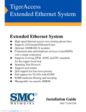
TigerAccess Extended Ethernet System
Brand:
SMC Networks
| Category:
Extender
| Size: 2.1 MB
Table of Contents
Installation Guide
1
Japan VCCI Class a
7
Safety Compliance
8
Underwriters Laboratories Compliance Statement
8
Table of Contents
11
1 About the Tigeraccess Extended Ethernet Switch
15
Overview
15
Extended Ethernet Technology
17
Switch Architecture
18
Management Options
18
Vlans
19
Multicast Switching
20
Traffic Priority
20
Spanning Tree Protocol
20
Description of Hardware
21
SMC7724M/VSW EE Switch
21
SMC7024/VSP and SMC7048/VSP EE Splitters
23
Extended Ethernet CPE
24
Status Leds
24
Optional Media Extender Modules
26
Optional 1000BASE-X GBIC Module (SMC7712GB)
26
Optional 1000BASE-T Module (SMC7712GT)
27
Optional 100BASE-FX Module (SMC7724FSSC)
27
Optional 100BASE-FX Module (SMC7724FMSC)
28
Optional 10/100BASE-TX Module (SMC7724T)
28
Power Supply Receptacle
29
Key Features
30
Extended Ethernet Features (CPE Side) Include
30
Extended Ethernet Features (CO Side) Include
31
System Features Include
31
Management Features Include
32
Network Planning
33
Introduction to Switching
33
Application Examples
34
Internet Connections
35
Remote Connections with Fiber Cable
36
Making VLAN Connections
37
Application Notes
38
3 Installing the Extended Ethernet Switch and Splitter 3-1
39
Preparing the Site
39
Installing Additional Equipment
41
Equipment Checklist
42
Package Contents
42
SMC7724M/VSW EE Switch
42
SMC7024/VSP or SMC7048/VSP EE Splitters
43
Optional Rack-Mounting Equipment
43
Mounting
44
Desktop or Shelf Mounting
47
Installing an Optional Module into the Switch
48
Installing a GBIC Transceiver
49
Installing an SFP Transceiver
50
Connecting to the Stack's Backplane
51
Connecting to a Power Source
52
Making Network Connections
53
Connecting to the Optional 1000BASE-T and 10/100BASE-TX Modules
53
Twisted-Pair Devices
53
Cabling Guidelines
53
Connecting RJ-21 Cables
54
Using Punch-Down Blocks
55
Using Patch Panels
56
Connecting the EE Switch to the EE Splitter
57
Fiber Optic Devices
57
Troubleshooting
59
Diagnosing Switch Indicators
59
Power and Cooling Problems
60
Installation
61
In-Band Access
61
Cables
63
Specifications
63
Twisted-Pair Cable and Pin Assignments
64
10BASE-T/100BASE-TX Pin Assignments
64
1000BASE-T Pin Assignments
66
1000BASE-T Cable Requirements
67
Cable Testing for Existing Category 5 Cable
67
Adjusting Existing Category 5 Cabling to Run 1000BASE-T
67
RJ-21 Port Pin Assignments
68
Port Pin Assignments
69
Console Port Pin Assignments
69
DB-9 Port Pin Assignments
69
Console Port to 9-Pin DTE Port on PC
69
Console Port to 25-Pin DTE Port on PC
70
Specifications
71
Switch Features
72
Extended Ethernet (EE) Switch
73
Management Features
73
Extended Ethernet (EE) Splitter
75
Slide-In Modules
77
Ordering Information
80
Glossary
81
Gigabit Ethernet
82
Network Diameter
84
Index
87
Advertisement
Related Products
SMC Networks VQC1100
SMC Networks VQZ100 Series
SMC Networks VR2110-N01
SMC Networks VXFA26C
SMC Networks VM122-M5-00A
SMC Networks VM131-01-35GA
SMC Networks VM1100-4N-32G
SMC Networks VM430-01-08
SMC Networks VM430-01-02
SMC Networks VM1000-4NU-32R
SMC Networks Categories
Switch
Control Unit
Controller
Network Router
Wireless Router
More SMC Networks Manuals
Login
Sign In
OR
Sign in with Facebook
Sign in with Google
Upload manual
Upload from disk
Upload from URL