Sign In
Upload
Manuals
Brands
National Instruments Manuals
Portable Generator
DAQArb 5411
National Instruments DAQArb 5411 Manuals
Manuals and User Guides for National Instruments DAQArb 5411. We have
2
National Instruments DAQArb 5411 manuals available for free PDF download: User Manual, Getting Started Manual
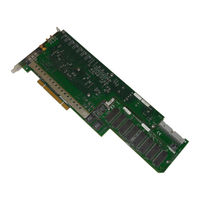
National Instruments DAQArb 5411 User Manual (84 pages)
High-Speed Arbitrary Waveform Generator
Brand:
National Instruments
| Category:
Portable Generator
| Size: 0.48 MB
Table of Contents
User Manual
1
Important Information
3
Table of Contents
4
Conventions Used in this Manual
9
Chapter 1 Introduction
10
About Your Daqarb 5411
10
What You Need to Get Started
11
Software Programming Choices
12
National Instruments Application Software
12
Appendix A
13
Appendix B
13
Appendix C
13
Figure 1-1. the Relationship between the Programming Environment
13
NI-DAQ Driver Software
13
Cabling
14
Optional Equipment
14
Unpacking
15
Chapter 2 Installation
16
Hardware Configuration
17
Installing the Optional Memory Module
17
Figure 3-1. Daqarb 5411 I/O Connector
18
Figure 3-2. Output Levels and Load Termination Using a 50
19
Chapter 3 Signal Connections
19
ARB Connector
19
Figure 3-3. SYNC Output and Duty Cycle
20
SYNC Connector
20
PLL Ref Connector
20
Dig out Connector
21
Connector Pin Assignments
21
Figure
21
Signal Descriptions
22
Figure 3-4. Daqarb 5411 50-Pin Digital Output Connector Pin Assignments
22
SHC50-68 50-Pin Cable Connector
23
Table 3-1. Digital Output Connector Signal Descriptions
23
Figure 3-5. SHC50-68 68-Pin Connector Pin Assignments
24
Power-Up and Reset Conditions
25
Chapter 4 Arb Operation
26
Figure 4-1. Daqarb 5411 Block Diagram
26
Waveform Generation
27
Figure
27
Update Rate
28
Arb Mode
28
Figure 4-2. Waveform Data Path Block Diagram
28
Waveform Size and Resolution
29
Waveform Memory
29
Figure 4-3. Waveform Memory Architecture
29
Minimum Buffer Size and Resolution
30
Waveform Linking and Looping
30
Figure
30
Figure 4-4. Waveform Linking and Looping
31
Waveform Staging
31
Figure 4-5. Waveform Staging Block Diagram
32
Direct Digital Synthesis (DDS) Mode
33
Figure 4-6. Waveform Generation Process
33
Figure 4-7. DDS Building Blocks
34
Frequency Resolution and Lookup Memory
35
Frequency Hopping and Sweeping
36
Triggering
36
Trigger Sources
36
Modes of Operation
37
Single Trigger Mode
37
Figure 4-8. Waveform Generation Trigger Sources
37
Continuous Trigger Mode
38
Figure 4-9. Single Trigger Mode for Arb Mode
38
Figure 4-10. Single Trigger Mode for DDS Mode
38
Stepped Trigger Mode
39
Figure 4-11. Continuous Trigger Mode for Arb Mode
39
Figure 4-12. Continuous Trigger Mode for DDS Mode
39
Burst Trigger Mode
40
Figure 4-13. Stepped Trigger Mode for Arb Mode
40
Marker Output Signal
41
Figure 4-14. Burst Trigger Mode for Arb Mode
41
Figure 4-15. Burst Trigger Mode for DDS Mode
41
Figure 4-16. Markers as Trigger Outputs
42
Analog Output
43
Figure 4-17. Analog Output and SYNC out Block Diagram
43
Figure 4-18. Waveform, Trigger, and Marker Timings
44
Output Attenuation
44
SYNC Output and Duty Cycle
44
Figure 4-19. Output Attenuation Chain
45
Output Impedance
45
Output Enable
46
Pre-Attenuation Offset
46
Phase-Locked Loops
47
Figure 4-20. Phase-Locked Loop (PLL) Architecture
47
Figure 4-21. Master/Slave Configurations for Phase Locking
48
Master/Slave Operation
48
Analog Filter Correction
49
Digital Pattern Generation
50
Figure 4-22. Analog Filter Correction
50
Figure 4-23. Digital Pattern Generator Data Path
51
Figure 4-24. Digital Pattern Generation Timing
51
RTSI Trigger Lines
52
Figure 4-25. Daqarb 5411 RTSI Trigger Lines and Routing
52
Calibration
53
Bus Interface
57
Operational Modes
57
Internal Clock
59
Figure B-1. Analog Filter and Signal Images Without Digital Filtering
60
Figure B-2. Digital Filter, Analog Filter, and Signal Images with Digital Filtering
61
Figure B-3. Waveform Updates
61
Configuration Form
65
Other Products
65
Advertisement
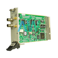
National Instruments DAQArb 5411 Getting Started Manual (35 pages)
Signal Generators
Brand:
National Instruments
| Category:
Test Equipment
| Size: 0.83 MB
Table of Contents
Table of Contents
1
Conventions
2
1 Verifying the System Requirements
3
2 Unpacking
4
3 Verifying the Kit Contents
4
EMI Gasket
5
Other Required Items
5
4 Installing the Software
5
5 Installing the Hardware
6
Cooling Considerations for PXI and PCI Devices
6
Installing PXI Modules
7
Uninstalling PXI Modules
8
Installing and Uninstalling PXI Express Modules
9
Installing PCI Devices
10
6 Power on Your Computer or PXI Chassis
11
7 Configuring and Testing in MAX
12
8 Setting up Synchronization for NI-Daqmx Devices in MAX
14
9 Generating Waveforms Interactively
15
Generating a Standard Waveform
16
Generating an Arbitrary Waveform
17
Generating a Video Signal (ni 5431 Only)
18
10 Generating Waveforms Programmatically
19
NI-FGEN Examples
19
NI-FGEN Instrument Driver
19
NI Composite Video Generator (ni 5431 Only)
20
11 Creating and Editing Waveforms
20
Appendix A: Front Panels
20
Ni Pxi/Pci-5401
21
Ni Pxi/Pci-5402/5406
23
Ni Pxi-5404
25
Ni Pxi-5411/5431
27
Ni Pci-5411/5431
29
Ni Pxi/Pci-5412/5421/5422/5441
30
NI Pxie-5442
32
Where to Go for Support
34
Advertisement
Related Products
National Instruments 5401
National Instruments 5402
National Instruments 5404
National Instruments 5406
National Instruments 5412
National Instruments 5421
National Instruments 5422
National Instruments 5431
National Instruments 5441
National Instruments 5442
National Instruments Categories
Control Unit
I/O Systems
Controller
Computer Hardware
Measuring Instruments
More National Instruments Manuals
Login
Sign In
OR
Sign in with Facebook
Sign in with Google
Upload manual
Upload from disk
Upload from URL