Sign In
Upload
Manuals
Brands
Motorola Manuals
Computer Hardware
MC68306
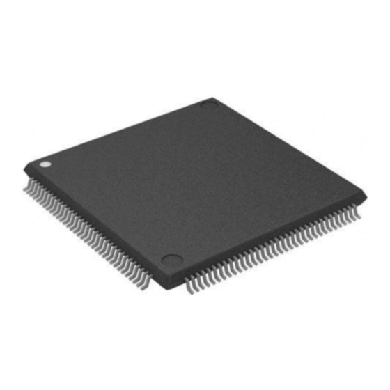
Motorola MC68306 Manuals
Manuals and User Guides for Motorola MC68306. We have
1
Motorola MC68306 manual available for free PDF download: User Manual
Motorola MC68306 User Manual (191 pages)
Integrated EC000 Processor
Brand:
Motorola
| Category:
Computer Hardware
| Size: 1.24 MB
Table of Contents
Table of Contents
4
Introduction
16
Figure 1-1. MC68306 Simplified Block Diagram
16
MC68EC000 Core Processor
17
On-Chip Peripherals
18
Serial Module
18
Chip Selects
19
DRAM Controller
19
Parallel Ports
19
Interrupt Controller
19
Clock
19
Bus Timeout Monitor
20
IEEE 1149.1 Test
20
Signal Descriptions
21
Figure 2-1. MC68306 Detailed Block Diagram
22
Table 2-1. Bus Signal Summary
23
Table 2-2. Chip Select Signal Summary
23
Table 2-3. DRAM Controller Signal Summary
23
Table 2-4. Interrupt and Parallel Port Signal Summary
24
Table 2-5. Clock and Mode Control Signal Summary
24
Bus Signals
25
Address Bus (A23-A1)
25
Table 2-6. Serial Module Signal Summary
25
Table 2-7. JTAG Signal Summary
25
Address Strobe (AS)
26
Bus Error (BERR )
26
Bus Request (BR)
26
Bus Grant (BG )
26
Bus Grant Acknowledge (BGACK)
26
Data Bus (D15-D0)
27
Data Transfer Acknowledge (DTACK)
27
DRAM Multiplexed Address Bus (DRAMA14-DRAMA0)
27
Processor Function Codes (FC2-FC0)
27
Halt (HALT)
27
Table 2-8. Function Code Outputs
27
Read/Write (R/W)
28
Table 2-9. Data Strobe Control of Data Bus
28
Lower Byte Write (LW )
29
Output Enable (OE)
29
Reset (RESET )
29
Chip Select Signals
29
DRAM Controller Signals
29
Column Address Strobe (CAS1- CAS0 )
29
Row Address Strobe (RAS1 -RAS0)
29
DRAM Write Signal (DRAMW)
29
Interrupt Control and Parallel Port Signals
29
Interrupt Request (IRQ7-IRQ1)
30
Interrupt Acknowledge (IACK7-IACK1)
30
Port a Signals (PA7-PA0)
30
Port B (PB7-PB0)
30
Clock and Mode Control Signals
30
Crystal Oscillator (EXTAL, XTAL)
30
Clock out (CLKOUT)
30
Address Mode (AMODE)
30
Serial Module Signals
30
Channel a Receiver Serial-Data Input (Rxda)
31
Channel a Transmitter Serial-Data Output (Txda)
31
Channel B Receiver Serial-Data Input (Rxdb)
31
Channel B Transmitter Serial-Data Output (Txdb)
31
Ctsa
31
Rtsa
31
Ctsb
31
Rtsb
31
Crystal Oscillator (X1, X2)
32
Ip2
32
Op3
32
JTAG Port Test Signals
32
Test Clock (TCK)
32
Test Mode Select (TMS)
32
Test Data in (TDI)
32
Test Data out (TDO)
32
Test Reset (TRST)
32
68000 Bus Operation Description
33
Data Transfer Operations
33
Read Cycle
33
Figure 3-1. Word Read Cycle Flowchart
34
Figure 3-2. Byte Read Cycle Flowchart
34
Figure 3-3. Read and Write Cycle Timing Diagram
35
Figure 3-4. Word and Byte Read Cycle Timing Diagram
35
Write Cycle
36
Figure 3-5. Word Write Cycle Flowchart
37
Figure 3-6. Byte Write Cycle Flowchart
38
Figure 3-7. Word and Byte Write Cycle Timing Diagram
38
Read-Modify-Write Cycle
39
Figure 3-8. Read-Modify-Write Cycle Flowchart
40
Figure 3-9. Read-Modify-Write Cycle Timing Diagram
41
CPU Space Cycle
43
Figure 3-10. Interrupt Acknowledge Cycle
43
Bus Arbitration
44
Figure 3-11. Interrupt Acknowledge Cycle Timing Diagram
44
Figure 3-12. Three-Wire Bus Arbitration Cycle Flowchart
45
Figure 3-13. Two-Wire Bus Arbitration Cycle Flowchart
46
Figure 3-14. Three-Wire Bus Arbitration Timing Diagram
47
Figure 3-15. Two-Wire Bus Arbitration Timing Diagram
47
Requesting the Bus
48
Receiving the Bus Grant
48
Acknowledgment of Mastership (3-Wire Bus Arbitration Only)
48
Bus Arbitration Control
49
Figure 3-16. External Asynchronous Signal Synchronization
49
Figure 3-17. Bus Arbitration Unit State Diagrams
50
Figure 3-18. Three-Wire Bus Arbitration Timing Diagram-Processor Active
51
Figure 3-19. Three-Wire Bus Arbitration Timing Diagram-Bus Inactive
52
Figure 3-20. Three-Wire Bus Arbitration Timing Diagram-Special Case
53
Figure 3-21. Two-Wire Bus Arbitration Timing Diagram-Processor Active
54
Figure 3-22. Two-Wire Bus Arbitration Timing Diagram-Bus Inactive
55
Bus Error and Halt Operation
56
Bus Error Operation
56
Figure 3-23. Two-Wire Bus Arbitration Timing Diagram-Special Case
56
Retrying the Bus Cycle
57
Figure 3-24. Bus Error Timing Diagram
57
Halt Operation
58
Figure 3-25. Retry Bus Cycle Timing Diagram
58
Double Bus Fault
59
Reset Operation
59
Figure 3-26. Halt Operation Timing Diagram
59
The Relationship of DTACK, BERR , and HALT
60
Figure 3-27. Reset Operation Timing Diagram
60
Asynchronous Operation
62
Figure 3-28 Fully Asynchronous Read Cycle
63
Figure 3-29. Fully Asynchronous Write Cycle
63
Figure 3-30. Pseudo-Asynchronous Read Cycle
64
Synchronous Operation
65
Figure 3-31. Pseudo-Asynchronous Write Cycle
65
Figure 3-32. Synchronous Read Cycle
67
Figure 3-33. Synchronous Write Cycle
68
EC000 Core Processor
69
Features
69
Processing States
69
Programming Model
70
Figure 4-1. Programmer's Model
70
Data Format Summary
71
Figure 4-2. Status Register
71
Table 4-1. Processor Data Formats
71
Addressing Capabilities Summary
72
Table 4-2. Effective Addressing Modes
72
Notation Conventions
73
Table 4-3. Notation Conventions
73
EC000 Core Instruction Set Overview
75
Table 4-4. EC000 Core Instruction Set Summary
76
Exception Processing
80
Figure 4-3. General Exception Processing Flowchart
81
Exception Vectors
82
Figure 4-4. General Form of Exception Stack Frame
82
Figure 4-5. Exception Vector Format
83
Figure 4-6. Address Translated from 8-Bit Vector Number
83
Processing of Specific Exceptions
84
Table 4-5. Exception Vector Assignments
84
Reset Exception
85
Interrupt Exceptions
85
Uninitialized Interrupt Exception
86
Spurious Interrupt Exception
86
Instruction Traps
86
Illegal and Unimplemented Instructions
86
Privilege Violations
87
Tracing
87
Bus Error
88
Address Error
89
Multiple Exceptions
89
Figure 4-7. Supervisor Stack Order for Bus or Address Error Exception
89
Table 4-6. Exception Grouping and Priority
90
System Operation
91
MC68306 Address Space
91
Table 5-1. MC68306 Memory Map
92
Register Description
93
System Register
93
Timer Vector Register
94
Bus Timeout Period Register
94
Interrupt Registers
95
Interrupt Control Register
95
Interrupt Status Register
96
I/O Port Registers
96
Port Pins Register
97
Port Direction Register
97
Port Data Register
98
Chip Selects
98
Chip Select Configuration Registers (High Half)
99
Chip Select Configuration Registers (Low Half)
100
Table 5-2. Chip Select Match Bits
101
DRAM Control Registers
102
Figure 5-1. Chip Select Expansion
102
Table 5-3. DRAM Address Multiplexer
103
DRAM Refresh Register
104
DRAM Bank Configuration Register (High Half)
104
DRAM Bank Configuration Register (Low Half)
105
Table 5-4. DRAM Bank Match Bits
106
Automatic DTACK Generation
107
Crystal Oscillator
107
Figure 5-2. Oscillator Circuit Diagram
108
Serial Module
109
Figure 6-1. Simplified Block Diagram
109
Module Overview
110
Serial Communication Channels a and B
111
Baud Rate Generator Logic
111
Timer/Counter
111
Interrupt Control Logic
111
Comparison of Serial Module to MC68681
112
Serial Module Signal Definitions
112
Channel a Transmitter Serial Data Output (Txda)
112
Channel a Receiver Serial Data Input (Rxda)
113
Channel B Transmitter Serial Data Output (Txdb)
113
Figure 6-2. External and Internal Interface Signals
113
Channel B Receiver Serial Data Input (Rxdb)
114
Channel a Request-To-Send (RTSA/OP0)
114
Rtsa
114
Op0
114
Channel B Request-To-Send (RTSB/OP1)
114
Rtsb
114
Op1
114
Channel a Clear-To-Send (CTSA/IP0)
114
Ctsa
114
Ip0
114
Operation
115
Baud Rate Generator
115
Transmitter and Receiver Operating Modes
115
Figure 6-3. Baud Rate Generator Block Diagram
115
Figure 6-4. Transmitter and Receiver Functional Diagram
116
Figure 6-5. Transmitter Timing Diagram
117
Transmitter
118
Receiver
119
FIFO Stack
119
Figure 6-6. Receiver Timing Diagram
119
Looping Modes
121
Automatic Echo Mode
121
Local Loopback Mode
121
Remote Loopback Mode
121
Multidrop Mode
122
Figure 6-7. Looping Modes Functional Diagram
122
Figure 6-8. Multidrop Mode Timing Diagram
123
Counter/Timer
124
Counter Mode
124
Timer Mode
124
Bus Operation
125
Read Cycles
125
Write Cycles
125
Interrupt Acknowledge Cycles
125
Register Description and Programming
125
Register Description
125
Auxiliary Control Register (DUACR)
126
Interrupt Status Register (DUISR)
126
Interrupt MASK Register (DUIMR)
126
Interrupt Vector Register (DUIVR)
126
Input Port Register
126
Mode Register 1 (DUMR1)
126
Figure 6-9. Serial Module Programming Model
126
Table 6-1. Pmx and PT Control Bits
128
Table 6-2. B/CX Control Bits
128
Output Port Control Register (DUOPCR)
129
Table 6-3. CMX Control Bits
129
Table 6-4. Sbx Control Bits
130
Table 6-5. Rcsx Control Bits
133
Table 6-6. Tcsx Control Bits
134
Table 6-7. Miscx Control Bits
135
Table 6-8. Tcx Control Bits
136
Table 6-9. Rcx Control Bits
136
Table 6-10. Counter/Timer Mode and Source Select Bits
139
Count Register Current MSB of Counter (DUCUR)
141
Count Register Current LSB of Counter (DUCLR)
141
Output Port Data Register (DUOP)
144
Start Counter Command Register
144
Stop Counter Command Register
144
Programming
145
Serial Module Initialization
145
I/O Driver Example
145
Interrupt Handling
145
Figure 6-10. Serial Module Programming Flowchart
146
Serial Module Initialization Sequence
151
IEEE 1149.1 Test Access Port
153
Overview
153
Figure 7-1. Test Access Port Block Diagram
154
TAP Controller
155
Boundary Scan Register
155
Figure 7-2. TAP Controller State Machine
155
Table 7-1. Boundary Scan Control Bits
156
Figure 7-3. Output Cell (O.cell)
159
Figure 7-4. Input Cell (I.cell)
159
Figure 7-5. Output Control Cell (En.cell)
160
Figure 7-6. Bidirectional Cell (Io.cell)
160
Instruction Register
161
Figure 7-7. Bidirectional Cell (Iox0.Cell)
161
Figure 7-8. General Arrangement for Bidirectional Pins
161
Table 7-3. Instructions
162
Extest (000)
162
Sample/Preload (110)
162
Bypass (010, 101, 111)
162
Clamp (011)
163
MC68306 Restrictions
163
Figure 7-9. Bypass Register
163
Non-IEEE 1149.1 Operation
164
Maximum Ratings
165
Thermal Characteristics
165
Power Considerations
166
AC Electrical Specification Definitions
166
Figure 8-1. Drive Levels and Test Points for AC Specifications
167
DC Electrical Specifications
168
AC Electrical Specifications-Clock Timing
168
AC Electrical Specifications-Read and Write
169
Figure 8-2. Clock Output Timing
169
Figure 8-3. Read Cycle Timing Diagram
171
Figure 8-4. Write Cycle Timing Diagram
172
AC Electrical Specifications-Chip Selects
173
Figure 8-5. Chip Select and Interrupt Acknowledge Timing Diagram
173
AC Electrical Specifications-Bus Arbitration
174
Figure 8-6. Bus Arbitration Timing Diagram
174
Figure 8-7. Bus Arbitration Timing Diagram
175
Bus Operation-DRAM Accesses AC Timing Specifications
176
Figure 8-8. DRAM Timing - 0-Wait Read, no Refresh
177
Figure 8-9. DRAM Timing - 1-Wait Write, no Refresh
178
Figure 8-10. DRAM Timing - 0- and 1-Wait Refresh
178
Serial Module Electrical Characteristics
179
Figure 8-11. DRAM Timing - 1-Wait, Test and Set
179
Serial Module AC Electrical Characteristics-Clock Timing
180
AC Electrical Characteristics-Port Timing
180
Figure 8-12. Clock Timing
180
Figure 8-13. Port Timing
180
AC Electrical Characteristics-Interrupt Reset
181
AC Electrical Characteristics-Transmitter Timing
181
Figure 8-14. Interrupt Reset Timing
181
Figure 8-15. Transmit Timing
181
AC Electrical Characteristics-Receiver Timing
182
Figure 8-16. Receive Timing
182
IEEE 1149.1 Electrical Characteristics
183
Figure 8-17. Test Clock Input Timing Diagram
183
Figure 8-18. Boundary Scan Timing Diagram
184
Figure 8-19. Test Access Port Timing Diagram
184
Ordering Information and Mechanical Data
185
Standard Ordering Information
185
Pin Assignments
186
Package Dimensions
188
Advertisement
Advertisement
Related Products
Motorola MC68302
Motorola DragonBall MC68328
Motorola MC68341
Motorola MC68VZ328
Motorola MC68020
Motorola MC68EC020
Motorola MC68HC000
Motorola MC68SEC000
Motorola MC68HC001
Motorola MC6805U2
Motorola Categories
Cell Phone
Two-Way Radio
Baby Monitor
Cordless Telephone
Radio
More Motorola Manuals
Login
Sign In
OR
Sign in with Facebook
Sign in with Google
Upload manual
Upload from disk
Upload from URL