Sign In
Upload
Manuals
Brands
Motorola Manuals
Computer Hardware
MC68302
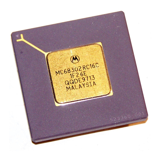
Motorola MC68302 Manuals
Manuals and User Guides for Motorola MC68302. We have
2
Motorola MC68302 manuals available for free PDF download: User Manual
Motorola MC68302 User Manual (480 pages)
Integrated Multiprotocol Processor
Brand:
Motorola
| Category:
Computer Hardware
| Size: 1.86 MB
Table of Contents
Table of Contents
5
Paragraph Title Page
6
Number Number
6
Table Title Page
22
Number Number
22
General Description
23
Block Diagram
23
Figure 1-1. MC68302 Block Diagram
24
General Description
24
MC68000/MC68008 Core
24
Features
25
MC68302 System Architecture
26
Figure 1-2. General-Purpose Microprocessor System Design
26
NMSI Communications-Oriented Environment
27
Figure 1-3. MC68302 System Design
27
Basic Rate ISDN or Digital Voice/Data Terminal
28
Figure 1-4. NMSI Communications-Oriented Board Design
29
Figure 1-5. Basic Rate IDL Voice/Data Terminal in ISDN
30
MC68000/MC68008 Core
31
Programming Model
31
MC68000/MC68008 Core
32
Figure 2-1. M68000 Programming Model
32
Instruction Set Summary
33
Figure 2-2. M68000 Status Register
33
Table 2-1. M68000 Data Addressing Modes
34
Table 2-2. M68000 Instruction Set Summary
35
Address Spaces
36
Table 2-3. M68000 Instruction Type Variations
36
Table 2-4. M68000 Address Spaces
37
Exception Processing
38
Exception Vectors
38
Table 2-5. M68000 Exception Vector Assignment
38
Exception Stacking Order
39
Figure 2-3. M68000 Bus/Address Error Exception Stack Frame
40
Figure 2-4. M68000 Short-Form Exception Stack Frame
40
Interrupt Processing
41
M68000 Signal Differences
41
MC68302 IMP Configuration Control
42
Figure 2-5. MC68302 IMP Configuration Control
42
MC68302 Memory Map
44
Table 2-6. System Configuration Register
44
Table 2-7. System RAM
44
Table 2-8. Parameter RAM
45
Table 2-9. Internal Registers
47
Event Registers
49
System Integration Block (SIB)
51
DMA Control
52
Key Features
52
IDMA Registers (Independent DMA Controller)
53
Figure 3-1. IDMA Controller Block Diagram
53
Channel Mode Register (CMR)
54
Source Address Pointer Register (SAPR)
56
Destination Address Pointer Register (DAPR)
56
Function Code Register (FCR)
57
Byte Count Register (BCR)
57
Channel Status Register (CSR)
57
Interface Signals
58
DREQ and DACK
58
Done
58
IDMA Operational Description
59
Channel Initialization
59
Data Transfer
59
Address Sequencing
60
Table 3-1. SAPR and DAPR Incrementing Rules
60
Transfer Request Generation
61
Table 3-2. IDMA Bus Cycles
61
Block Transfer Termination
62
IDMA Programming
63
DMA Bus Arbitration
64
Bus Exceptions
64
Reset
65
Bus Error
65
Halt
65
Relinquish and Retry
65
Interrupt Controller
65
Overview
66
IMP Interrupt Processing Overview
66
Figure 3-2. Interrupt Controller Block Diagram
66
Interrupt Controller Overview
67
Interrupt Priorities
68
INRQ and EXRQ Priority Levels
68
INRQ Interrupt Source Priorities
69
Nested Interrupts
69
Table 3-3. EXRQ and INRQ Prioritization
69
Table 3-4. INRQ Prioritization Within Interrupt Level 4
69
Masking Interrupt Sources and Events
70
Interrupt Vector
71
Figure 3-3. Interrupt Request Logic Diagram for Sccs
71
Figure 3-4. SCC1 Vector Calculation Example
73
Table 3-5. Encoding the Interrupt Vector
73
Interrupt Controller Programming Model
74
Global Interrupt Mode Register (GIMR)
74
Interrupt Pending Register (IPR)
76
Interrupt Mask Register (IMR)
77
Interrupt In-Service Register (ISR)
78
Interrupt Handler Examples
78
Parallel I/O Ports
79
Port a
79
Figure 3-5. Parallel I/O Block Diagram for PA0
80
Port B
81
Pb7-Pb0
81
Table 3-6. Port a Pin Functions
81
Pb11-Pb8
82
I/O Port Registers
82
Table 3-7. Port B Pin Functions
82
Dual-Port RAM
83
Figure 3-6. Parallel I/O Port Registers
83
Timers
85
Figure 3-7. RAM Block Diagram
85
Timer Key Features
86
Figure 3-8. Timer Block Diagram
86
General Purpose Timer Units
87
Timer Mode Register (TMR1, TMR2)
87
Timer Reference Registers (TRR1, TRR2)
88
Timer Capture Registers (TCR1, TCR2)
89
Timer Counter (TCN1, TCN2)
89
Timer Event Registers (TER1, TER2)
89
General Purpose Timer Example
90
Timer Example 1
90
Timer Example 2
90
Timer 3 - Software Watchdog Timer
91
Software Watchdog Timer Operation
91
Software Watchdog Reference Register (WRR)
91
Software Watchdog Counter (WCN)
92
External Chip-Select Signals and Wait-State Logic
92
Figure 3-9. Chip-Select Block Diagram
94
Chip-Select Logic Key Features
95
Chip-Select Registers
95
Base Register (BR3-BR0)
95
Option Registers (OR3-OR0)
97
Table 3-8. DTACK Field Encoding
97
Chip Select Example
98
On-Chip Clock Generator
99
Figure 3-10. Using an External Crystal
99
System Control
100
System Control Register (SCR)
100
Figure 3-11. System Control Register
100
System Status Bits
101
Table 3-9. SCR Register Bits
101
System Control Bits
102
Disable CPU Logic (M68000)
104
Bus Arbitration Logic
106
Internal Bus Arbitration
106
Figure 3-12. IMP Bus Arbiter
107
External Bus Arbitration
108
Table 3-10. Bus Arbitration Priority Table
108
Hardware Watchdog
109
Reducing Power Consumption
110
Power-Saving Tips
110
Low-Power (Standby) Modes
110
Low-Power Mode
111
Lowest Power Mode
112
Lowest Power Mode with External Clock
112
Clock Control Register
114
Freeze Control
115
Dynamic Ram Refresh Controller
116
Hardware Setup
116
DRAM Refresh Controller Bus Timing
117
Refresh Request Calculations
117
Figure 3-13. DRAM Control Block Diagram
117
Initialization
118
DRAM Refresh Memory Map
118
Table 3-11. DRAM Refresh Memory Map Table
118
Programming Example
119
Communications Processor (CP)
121
Main Controller
121
Figure 4-1. Simplified CP Architecture
122
SDMA Channels
123
Figure 4-2. Three Serial Data Flow Paths
124
Command Set
125
Command Execution Latency
127
Serial Channels Physical Interface
127
Figure 4-3. NMSI Physical Interface
128
Figure 4-4. Multiplexed Mode on SCC1 Opens Additional Configuration Possibilities
129
Table 4-1. the Five Possible SCC Combinations
129
Figure 4-5. Serial Channels Physical Interface Block Diagram
130
IDL Interface
131
Figure 4-6. IDL Bus Signals
131
Figure 4-7. IDL Terminal Adaptor
132
GCI Interface
134
Figure 4-8. GCI Bus Signals
135
PCM Highway Mode
136
Table 4-2. PCM Highway Mode Pin Functions
137
Table 4-3. PCM Channel Selection
137
Figure 4-9. Two PCM Sync Methods
138
Nonmultiplexed Serial Interface (NMSI)
139
Serial Interface Registers
139
Serial Interface Mode Register (SIMODE)
139
Figure 4-10. PCM Channel Assignment on a T1/CEPT Line
139
Serial Interface Mask Register (SIMASK)
142
Serial Communication Controllers (Sccs)
142
SCC Features
144
SCC Configuration Register (SCON)
144
Figure 4-11. SCC Block Diagram
144
Asynchronous Baud Rate Generator Examples
146
Figure 4-12. SCC Baud Rate Generator
146
Synchronous Baud Rate Generator Examples
147
SCC Mode Register (SCM)
147
Table 4-4. Typical Bit Rates of Asynchronous Communication
147
Table 4-5. Transmit Data Delay (TCLK Periods)
148
Figure 4-13. Output Delays from RTS Low, Synchronous Protocol
149
Figure 4-14. Output Delays from CTS Low, Synchronous Protocol
149
SCC Data Synchronization Register (DSR)
151
Buffer Descriptors Table
152
Figure 4-15. Memory Structure
152
Figure 4-16. SCC Buffer Descriptor Format
153
SCC Parameter RAM Memory Map
154
Data Buffer Function Code Register (TFCR, RFCR)
155
Table 4-6. SCC Parameter RAM Memory Map
155
Maximum Receive Buffer Length Register (MRBLR)
156
Receiver Buffer Descriptor Number (RBD#)
156
Transmit Buffer Descriptor Number (TBD#)
156
Other General Parameters
157
SCC Initialization
157
Interrupt Mechanism
158
SCC Event Register (SCCE)
158
SCC Mask Register (SCCM)
159
SCC Status Register (Sccs)
159
Bus Error on SDMA Access
160
SCC Transparent Mode
161
Disabling the Sccs
162
UART Controller
163
Figure 4-17. UART Frame Format
163
Normal Asynchronous Mode
165
Asynchronous DDCMP MODE
166
UART Memory Map
166
Table 4-7. UART Specific Parameter RAM
166
UART Programming Model
168
UART Command Set
169
UART Address Recognition
170
Figure 4-18. Two Configurations of UART Multidrop Operation
170
UART Control Characters and Flow Control
171
Figure 4-19. UART Control Characters Table
171
Send Break
173
Send Preamble (IDLE)
173
Wakeup Timer
173
UART Error-Handling Procedure
174
Fractional Stop Bits
175
UART Mode Register
176
UART Receive Buffer Descriptor (Rx BD)
177
Figure 4-20. UART Receive Buffer Descriptor
178
Figure 4-21. UART Rx BD Example
179
UART Transmit Buffer Descriptor (Tx BD)
181
Figure 4-22. UART Transmit Buffer Descriptor
181
UART Event Register
183
Figure 4-23. UART Interrupt Events Example
184
UART MASK Register
185
S-Records Programming Example
185
HDLC Controller
186
Figure 4-24. Typical HDLC Frame
186
HDLC Channel Frame Transmission Processing
188
HDLC Channel Frame Reception Processing
188
HDLC Memory Map
189
HDLC Programming Model
189
Table 4-8. HDLC-Specific Parameter RAM
189
HDLC Command Set
190
HDLC Address Recognition
191
HDLC Maximum Frame Length Register (MFLR)
191
Figure 4-25. HDLC Address Recognition Examples
191
HDLC Error-Handling Procedure
192
HDLC Mode Register
193
HDLC Receive Buffer Descriptor (Rx BD)
195
Figure 4-26. HDLC Receive Buffer Descriptor
195
Figure 4-27. HDLC Receive BD Example
196
HDLC Transmit Buffer Descriptor (Tx BD)
198
Figure 4-28. HDLC Transmit Buffer Descriptor
198
HDLC Event Register
200
Figure 4-29. HDLC Interrupt Events Example
201
HDLC Mask Register
202
BISYNC Controller
202
Figure 4-30. Typical BISYNC Frames
203
Bisync Channel Frame Transmission Processing
204
Bisync Channel Frame Reception Processing
205
Bisync Memory Map
205
BISYNC Command Set
206
Table 4-9. BISYNC Specific Parameter RAM
206
BISYNC Control Character Recognition
207
Figure 4-31. BISYNC Control Characters Table
208
BSYNC-BISYNC SYNC Register
209
BDLE-BISYNC DLE Register
209
BISYNC Error-Handling Procedure
210
BISYNC Mode Register
211
BISYNC Receive Buffer Descriptor (Rx BD)
213
Figure 4-32. BISYNC Receive Buffer Descriptor
213
BISYNC Transmit Buffer Descriptor (Tx BD)
215
Figure 4-33. BISYNC Transmit Buffer Descriptor
215
BISYNC Event Register
217
BISYNC Mask Register
218
Programming the BISYNC Controllers
219
DDCMP Controller
220
Figure 4-34. Typical DDCMP Frames
220
DDCMP Channel Frame Transmission Processing
221
DDCMP Channel Frame Reception Processing
222
Figure 4-35. DDCMP Transmission/Reception Summary
222
DDCMP Memory Map
223
DDCMP Programming Model
224
DDCMP Command Set
224
Table 4-10. DDCMP Specific Parameter RAM
224
DDCMP Control Character Recognition
225
DDCMP Address Recognition
226
DDCMP Error-Handling Procedure
226
DDCMP Mode Register
228
DDCMP Receive Buffer Descriptor (Rx BD)
229
Figure 4-36. DDCMP Receive Buffer Descriptor
229
DDCMP Transmit Buffer Descriptor (Tx BD)
232
Figure 4-37. DDCMP Transmit Buffer Descriptor
232
DDCMP Event Register
234
DDCMP Mask Register
235
Controller
235
Bit Rate Adaption of Synchronous Data Signaling Rates up to 19.2 Kbps
236
Rate Adaption of 48- and 56-Kbps User Rates to 64 Kbps
236
Figure 4-38. Two-Step Synchronous Bit Rate Adaption
236
Adaption for Asynchronous Rates up to 19.2 Kbps
237
Controller Overview
237
V.110 Controller Overview
237
Figure 4-39. Three-Step Asynchronous Bit Rate Adaption
237
Programming Model
238
Error-Handling Procedure
238
Receive Buffer Descriptor (Rx BD)
238
Figure 4-40. V.110 Receive Buffer Descriptor
239
Transmit Buffer Descriptor (Tx BD)
240
Figure 4-41. V.110 Transmit Buffer Descriptor
240
Event Register
241
Mask Register
242
Transparent Controller
242
Transparent Channel Buffer Transmission Processing
243
Transparent Channel Buffer Reception Processing
244
Transparent Memory Map
245
Table 4-11. Transparent-Specific Parameter RAM
245
Transparent Commands
246
Transparent Synchronization
246
Transparent Error-Handling Procedure
248
Transparent Mode Register
249
Transparent Receive Buffer Descriptor (Rxbd)
250
Figure 4-42. Transparent Receive Buffer Descriptor
250
Transparent Transmit Buffer Descriptor (Tx BD)
251
Figure 4-43. Transparent Transmit Buffer Descriptor
251
Transparent Event Register
253
Transparent Mask Register
254
Serial Communication Port (SCP)
254
Figure 4-44. SCP Timing
255
SCP Programming Model
256
SCP Transmit/Receive Buffer Descriptor
257
SCP Transmit/Receive Processing
257
Figure 4-45. SCP Vs. SCC Pin Multiplexing
257
Serial Management Controllers (Smcs)
258
Overview
258
Using IDL with the Smcs
258
Using GCI with the Smcs
258
SMC Programming Model
259
SMC Commands
260
SMC Memory Structure and Buffers Descriptors
260
SMC1 Receive Buffer Descriptor
261
SMC1 Transmit Buffer Descriptor
262
SMC2 Receive Buffer Descriptor
262
SMC2 Transmit Buffer Descriptor
263
SMC Interrupt Requests
263
Signal Description
265
Functional Groups
265
Table 5-1. Signal Definitions
265
Power Pins
266
Signal Description
267
Clocks
268
Figure 5-2. Clock Pins
268
System Control
269
Figure 5-3. System Control Pins
269
Address Bus Pins (A23-A1)
271
Data Bus Pins (D15-D0)
271
Bus Control Pins
272
Figure 5-7. External Address/Data Buffer
273
Bus Arbitration Pins
274
Interrupt Control Pins
275
MC68302 Bus Interface Signal Summary
276
Table 5-2. Bus Signal Summary—Core and External Master
276
Physical Layer Serial Interface Pins
277
Table 5-3. Bus Signal Summary—Idma and SDMA
277
Table 5-4. Serial Interface Pin Functions
277
Typical Serial Interface Pin Configurations
278
NMSI1 or ISDN Interface Pins
278
Figure 5-10. NMSI1 or ISDN Interface Pins
278
Table 5-5. Typical ISDN Configurations
278
Table 5-6. Typical Generic Configurations
278
Table 5-7. Mode Pin Functions
279
Table 5-8. PCM Mode Signals
280
NMSI2 Port or Port a Pins
281
Figure 5-11. NMSI2 Port or Port a Pins
281
NMSI3 Port or Port a Pins or SCP Pins
282
Figure 5-12. NMSI3 Port or Port a Pins or SCP Pins
282
Table 5-9. Baud Rate Generator Outputs
282
IDMA or Port a Pins
283
Figure 5-13. IDMA or Port a Pins
283
IACK or PIO Port B Pins
284
Timer Pins
284
Figure 5-14. IACK or PIO Port B Pins
284
Figure 5-15. Timer Pins
285
Parallel I/O Pins with Interrupt Capability
286
Chip-Select Pins
286
Figure 5-16. Port B Parallel I/O Pins with Interrupt
286
Figure 5-17. Chip-Select Pins
286
No-Connect Pins
287
When to Use Pullup Resistors
287
Electrical Characteristics
289
Maximum Ratings
289
Thermal Characteristics
289
Power Considerations
290
Power Dissipation
291
DC Electrical Characteristics
291
DC Electrical Characteristics-NMSI1 in IDL Mode
293
AC Electrical Specifications-Clock Timing
293
AC Electrical Specifications-IMP Bus Master Cycles
294
Figure 6-2. Read Cycle Timing Diagram
297
Figure 6-3. Write Cycle Timing Diagram
298
Figure 6-4. Read-Modify-Write Cycle Timing Diagram
299
Figure 6-5. Bus Arbitration Timing Diagram
300
AC Electrical Specifications-DMA
301
Figure 6-6. DMA Timing Diagram (IDMA)
302
Figure 6-7. DMA Timing Diagram (SDMA)
303
AC Electrical Specifications-External Master Internal Asynchronous Read/Write Cycles
304
Figure 6-8. External Master Internal Asynchronous Read Cycle Timing Diagram
305
Figure 6-9. External Master Internal Asynchronous Write Cycle Timing Diagram
306
AC Electrical Specifications-External Master Internal Synchronous Read/Write Cycles
307
Figure 6-10. External Master Internal Synchronous Read Cycle Timing Diagram
308
Figure 6-12. External Master Internal Synchronous Write Cycle Timing Diagram
310
AC Electrical Specifications-Internal Master Internal Read/Write Cycles
311
Figure 6-13. Internal Master Internal Read/Write Cycle Timing Diagram
311
AC Electrical Specifications-Chip-Select Timing Internal Master
312
AC Electrical Specifications-Chip-Select Timing External Master
313
Figure 6-14. Internal Master Chip-Select Timing Diagram
313
AC Electrical Specifications-Parallel I/O
314
Figure 6-15. External Master Chip-Select Timing Diagram
314
AC Electrical Specifications-Interrupts
315
Figure 6-16. Parallel I/O Data-In/Data-Out Timing Diagram
315
Figure 6-17. Interrupts Timing Diagram
315
AC Electrical Specifications-Timers
316
Figure 6-18. Timers Timing Diagram
316
AC Electrical Specifications-Serial Communications Port
317
Figure 6-19. Serial Communication Port Timing Diagram
317
AC Electrical Specifications-IDL Timing
318
Figure 6-20. IDL Timing Diagram
319
AC Electrical Specifications-GCI Timing
320
Figure 6-21. GCI Timing Diagram
321
AC Electrical Specifications-PCM Timing
322
Figure 6-22. PCM Timing Diagram (SYNC Envelopes Data)
323
Figure 6-23. PCM Timing Diagram (SYNC Prior to 8-Bit Data)
323
AC Electrical Specifications-NMSI Timing
324
Figure 6-24. NMSI Timing Diagram
325
Mechanical Data and Ordering Information
327
Pin Assignments
327
Pin Grid Array (PGA)
327
Plastic Surface Mount (PQFP)
328
Thin Surface Mount (TQFP)
329
Package Dimensions
330
Pin Grid Array
330
Plastic Surface Mount (PQFP)
331
Thin Surface Mount (TQFP)
332
Ordering Information
333
Appendix Ascc Performance
335
Appendix B Development Tools and Support
339
Motorola Software Overview
339
Motorola Software Modules
339
Figure B-1. Software Overview
341
Third-Party Software Support
344
In-Circuit Emulation Support
344
302 Family ADS System
344
Figure B-2. MC68302FADS
346
Appendix C RISC Microcode from RAM
347
SS7 Protocol Support
348
Centronics Transmission Controller
348
Centronics Reception Controller
349
Profibus Controller
349
C.4 Profibus Controller
349
Autobaud Support Package
349
Microcode from RAM Initialization Sequence
350
Appendix D MC68302 Applications
351
Minimum System Configuration
351
System Configuration
351
D.1.1 System Configuration
351
Figure D-1. MC68302 Minimum System Configuration (Sheet 1 of
352
Reset Circuit
353
Figure D-2. MC68302 Minimum System Configuration (Sheet 2 of
353
D.1.2 Reset Circuit
353
Memory Interface
354
Memory Circuit
354
D.1.3 Memory Interface
354
D.1.4 Memory Circuit
354
Memory Timing Analysis
354
Switching the External ROM and RAM Using the MC68302
355
Conditions at Reset
355
D.2.1 Conditions at Reset
355
First Things First
355
Switching Process
356
D.2.3 Switching Process
356
MC68302 Buffer Processing and Interrupt Handling
357
Buffer Descriptors Definition
357
Figure D-4. Transmit and Receive BD Tables
358
MC68302 Buffer Processing
358
New Pointers
359
Figure D-5. Pointer During Execution
359
D.3.3 New Pointers
359
Initial Conditions
360
Transmit Algorithm
360
Interrupt Routine
360
D.3.4 Initial Conditions
360
D.3.5 Transmit Algorithm
360
D.3.6 Interrupt Routine
360
Final Comments
361
D.3.7 Final Comments
361
HDLC Code Listing
361
Configuring a Uart on the MC68302
367
Purpose of the Code
367
Organization of Buffers
368
Figure D-6. Transmit and Receive BD Tables and Buffers
368
D.4.2 Organization of Buffers
368
Assumptions about the System
369
UART Features Not Discussed
369
UART Code Listing
369
IDMA Overview
373
D.5 Independent DMA in the MC68302
373
D.5.1 IDMA Overview
373
IDMA Software Initialization
374
IDMA Bus Arbitration Signals
374
Triggering External IDMA Transfers
374
Performing Internally Generated IDMA Transfers
374
Table D-2. Channel Mode Register Bits
375
External Cycles Examples
376
Figure D-7. Typical IDMA External Cycles (Normal Operation)
377
Figure D-8. Typical IDMA External Cycles Showing Block Transfer Termination
378
Figure D-9. Typical IDMA Source to Word Destination IDMA Cycles
378
Table D-3. Channel Status Register Bits
378
Figure D-10. Burst Mode Cycles
379
Internal Interrupt Sequence
379
Final Notes
380
Figure D-11. ISDN Voice/Data Terminal
380
D.5.8 Final Notes
380
MC68302 Multiprotocol Controller Tied to IDL Bus Forms and ISDN Voice/Data Terminal
380
M68000 Core
381
Communications Processor
381
D.6.1 M68000 Core
381
System Integration Block
381
D.6.2 Communications Processor
381
IDL Bus
381
D.6.4 IDL Bus
381
Figure D-12. IDL Bus Boundaries
382
IDL Bus Specification
382
Figure D-13. IDL Frame Structure
383
IMP/IDL Interconnection
383
Figure D-14. IDL Bus to Other Slaves
384
Figure D-15. Serial Interface Configuration
385
Serial Interface Configuration
385
SCC Configuration
386
D.6.8 SCC Configuration
386
Parallel L/O Port a Configuration
387
SCP Bus
387
D.6.10 SCP Bus
387
SCP Configuration
388
Figure D-16. SCP Bus Interconnection
388
D.6.11 SCP Configuration
388
SCP Data Transactions
388
Additional IMP to S/T Chip Connections
389
Figure D-17. Discrete Signal Interconnection
390
Initialization of the MC145475
390
Figure D-18. CODEC/IDL Electrical Connection
391
MC145554 CODEC Filter
391
Interfacing a Master MC68302 to One or more Slave Mc68302S
391
Figure D-19. Typical Slave Mode Example
392
Synchronous Vs. Asynchronous Accesses
393
Clocking
393
Programming the Base Address Registers (Bars
393
D.7.2 Clocking
393
D.7.3 Programming the Base Address Registers (Bars)
393
Dealing with Interrupts
394
Arbitration
394
D.7.5 Arbitration
394
Final Notes
395
D.7.6 Final Notes
395
Using the MC68302 Transparent Mode
395
Transparent Mode Definition
395
Figure D-20. Dual Master-Slave System
396
Applications for Transparent Mode
396
Physical Interface to Accompany Transparent Mode
397
Figure D-21. NMSI Pin Definitions
398
Figure D-22. Multiplexed Modes Example
399
General Transparent Mode Behavior
400
Transparent Mode with the NMSI Physical Interface
402
Figure D-23. Simplest Transmit Case in NMSI
403
Figure D-24. Simplest Receive Case in NMSI
403
Figure D-25. Using CTS in the NMSI Transmit Case
404
Figure D-26. Using CD (Sync) in the NMSI Transmit Case
405
Figure D-27. Using CD (Sync) in the NMSI Receive Case
406
Other NMSI Modes
406
Figure D-28. External Loopback with RTS Connected to CD
406
BISYNC Mode
406
D.8.6.1 BISYNC Mode
406
Transync Mode
408
D.8.6.2 Transync Mode
408
Gating Clocks in NMSI Mode
408
Using Transparent Mode with PCM Highway Mode
410
Table D-4. PCM Highway Pin Names and Functions
410
Table D-5 PCM Highway Channel Selection with Llsy0 and L1SY1
410
Figure D-29. Routing Channels in PCM Envelope Mode
411
Figure D-30. PCM Transmission Timing Technique
413
PCM Mode Final Thoughts
414
Using Transparent Mode with IDL and GCI
414
Initializing Transparent Mode
415
Special Uses of Transparent Mode
417
5- or 6-Bit UART
417
Synchronous UART
417
D.8.12.1 5- or 6-Bit UART
417
D.8.12.2 Synchronous UART
417
SCP as a Transparent Mode Alternative
418
Transparent Mode Summary
418
Figure D-31. SCP Timing
419
An Appletalk Node with the MC68302 and MC68195
419
Overview of the Board
420
Important Side Notes
420
Figure D-32. Local Talk Adaptor Board
421
Advertisement
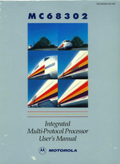
Motorola MC68302 User Manual (290 pages)
Integrated Multi-Protocol Processor
Brand:
Motorola
| Category:
Computer Hardware
| Size: 21.09 MB
Table of Contents
Table of Contents
6
Block Diagram
18
General Description
18
Features
20
MC68302 System Architecture
21
NMSI Communications-Oriented Environment
23
Basic Rate ISDN or Digital Voice/Data Terminal
23
Programming Model
28
MC68000/MC68008 Core
28
Instruction Set Summary
31
Address Spaces
35
Exception Processing
36
Exception Vectors
36
Exception Stacking Order
38
Interrupt Processing
39
M68000 Signal Differences
40
MC68302 IMP Configuration Control
40
MC68302 Memory Map
42
System Integration Block (SIB)
48
Key Features
50
IDMA Registers
51
Channel Mode Register (CMR)
52
Source Address Pointer Register (SAPR)
54
Destination Address Pointer Register (DAPR)
55
Function Code Register (FCR)
55
Byte Count Register (BCR)
55
Channel Status Register (CSR)
55
Interface Signals
56
DREQ and DACK
56
Done
56
IDMA Operational Description
57
Channel Initialization
57
Data Transfer
57
Address Sequencing
58
Transfer Request Generation
59
Block Transfer Termination
60
IDMA Programming
61
OMA Bus Arbitration
62
Bus Exceptions
63
Reset
63
Bus Error
63
Halt
64
Retry
64
Interrupt Controller
64
Operation
65
Interrupt Priorities
67
INRQ and EXRQ Priority Levels
67
INRQ Interrupt Source Priorities
68
Nested Interrupts
69
Masking Interrupt Sources and Events
69
Interrupt Vector Generation
70
Interrupt Controller Programming Model
70
Global Interrupt Mode Register (GIMR)
71
Interrupt Pending Register (IPR)
73
Interrupt Mask Register (IMR)
74
Interrupt In-Service Register (ISR)
74
Parallel Ports
75
Port a
75
Port B
76
Pb7-Pbo
76
Pb11-Pb8
78
1/0 Port Registers
78
Dual-Port RAM
78
Timers
81
Timer Key Features
82
General-Purpose Timer Units
82
Timer Reference Registers (TRR1, TRR2)
84
Timer Capture Registers (TCR1, TCR2)
84
Timer Counter (Tcnl, TCN2)
85
Timer Event Registers (TER1, TER2)
85
Watchdog Timer
85
Watchdog Timer Operation
86
Watchdog Reference Register (WRR)
86
Watchdog Counter (WCN)
87
External Chip-Select Signals and Wait-State Logic
87
Chip-Select Logic Key Features
89
Chip-Select Registers
89
Base Register (BR3-BRO)
89
Option Registers (OR3-0RO)
90
On-Chip Clock Generator
92
System Control
93
System Control Register (SCR)
94
System Status Bus
94
System Control Bits
95
Disable CPU Logic (M68000)
97
Bus Arbitration Logic
98
Hardware Watchdog
98
Low-Power (Standby) Modes
100
Freeze Control
102
Main Controller
104
SDMA Channels
104
Communications Processor (CP)
104
Command Set
106
Serial Channels Physical Interface
108
IDL Interface
108
GCI Interface
112
PCM Highway Mode
116
Nonmultiplexed Serial Interface (NMSI)
117
Serial Interface Registers
117
Serial Interface Mode Register (Simode)
117
Serial Communication Controllers (Sccs)
120
SCC Features
122
SCC Configuration Register (SCON)
123
Asynchronous Baud Rate Generator Examples
125
Synchronous Baud Rate Generator Examples
125
SCC Mode Register (SCM)
126
SCC Data Synchronization Register (DSR)
127
Buffer Descriptors Table
128
SCC Parameter RAM Memory Map
130
Data Buffer Function Code Register (TFCR, RFCR)
130
Maximum Receive Buffer Length Register (MRBLR)
131
Receiver Buffer Descriptor Number (RBD#)
131
Transmit Buffer Descriptor Number (TBD#)
131
SCC Initialization
131
Interrupt Mechanism
132
SCC Event Register (SCCE)
132
SCC Mask Register (SCCM)
132
SCC Status Register (SCCS)
132
SCC Transparent Mode Support
134
Power Saving with Sccs
135
UART Controller
136
Normal Asynchronous Mode
138
Asynchronous DDCMP Mode
138
UART Memory Map
138
UART Programming Model
139
UART Command Set
140
UART Address Recognition
141
UART Control Character Recognition
142
Send Break
143
Send Preamble (IDLE)
143
Wakeup Timer
144
UART Error-Handling Procedure
144
UART Mode Register
146
UART Transmit Buffer Descriptor (Tx BD)
151
UART Event Register
152
UART Mask Register
153
S-Records Programming Example
154
Serial Interface Mask Register (SIMASK)
120
HDLC Controller
155
HDLC Channel Frame Transmission Processing
156
HDLC Channel Frame Reception Processing
157
HDLC Memory Map
157
HDLC Programming Model
158
HDLC Command Set
158
HDLC Address Recognition
160
HDLC Maximum Frame Length Register (MFLR)
160
HDLC Error-Handling Procedure
160
HDLC Mode Register
163
HDLC Receive Buffer Descriptor (Rx BD)
164
HDLC Transmit Buffer Descriptor (Tx BD)
166
HDLC Event Register
168
HDLC Mask Register
169
BISYNC Controller
169
BISYNC Channel Frame Reception Processing
171
BISYNC Command Set
173
BISYNC Control Character Recognition
175
BSYNC-BISYNC SYNC Register
177
BDLE-BISYNC OLE Register
177
BISYNC Mode Register
179
Bl SYNC Transmit Buffer Descriptor (Tx BO)
184
BISYNC Mask Register
187
DDCMP Controller
189
DDCMP Channel Frame Transmission Processing
190
DDCMP Channel Frame Reception Processing
191
DDCMP Memory Map
192
DDCMP Programming Model
192
DDCMP Command Set
193
DDCMP Control Character Recognition
194
DDCMP Address Recognition
195
DDCMP Error-Handling Procedure
195
DDCMP Mode Register
198
DDCMP Transmit Buffer Descriptor (Tx BD)
202
DDCMP Event Register
205
DDCMP Mask Register
205
Controller
205
Bit Rate Adaption of Synchronous Data Signaling Rates
205
Rate Adaption of 48- and 56-Kbps User Rates to 64 Kbps
206
Adaption for Asynchronous Rates up to 19.2 Kbps
206
Controller Overview
207
Programming Model
207
Error-Handling Procedure
208
Receive Buffer Descriptor (Rx BD)
208
Transmit Buffer Descriptor (Tx BD)
210
Event Register
212
Mask Register
213
Serial Communication Port (SCP)
213
SCP Programming Model
214
Serial Management Controllers (Smcs)
215
SCP Transmit/Receive Buffer Descriptor
215
SCP Transmit/Receive Processing
215
Overview
216
Using IDL with the Smcs
216
Using GCI with the Smcs
216
SMC Programming Model
218
SMC Memory Structure and Buffers Descriptors
219
SMC1 Receive Buffer Descriptor
219
SMC1 Transmit Buffer Descriptor
221
SMC2 Receive Buffer Descriptor
222
SMC2 Transmit Buffer Descriptor
222
SMC Interrupt Requests
223
Signal Description
224
Functional Groups
225
Power Pins
225
Clocks
225
System Control
227
Address Bus Pins A23-A 1
228
Bus Control Pins
229
Bus Arbitration Pins
231
Interrupt Control Pins
232
MC68302 Bus Interface Signal Summary
233
Physical Layer Serial Interface Pins
234
Nmsl1 or ISDN Interface Pins
235
Nmsl2 Port or Port a Pins
237
Nmsl3 Port or Port a Pins or SCP Pins
238
IDMA Pins or Port a Pins
239
IACK or PIO Port B Pins
239
Timer Pins
240
Parallel 1/0 Pins with Interrupt Capability
240
Chip-Select Pins
241
Maximum Ratings
242
Thermal Characteristics
242
Power Considerations
243
Power Dissipation
243
Advertisement
Related Products
Motorola MC68306
Motorola DragonBall MC68328
Motorola MC68341
Motorola MC68VZ328
Motorola MC68020
Motorola MC68EC020
Motorola MC68HC000
Motorola MC68SEC000
Motorola MC68HC001
Motorola MC6805U2
Motorola Categories
Cell Phone
Two-Way Radio
Baby Monitor
Cordless Telephone
Radio
More Motorola Manuals
Login
Sign In
OR
Sign in with Facebook
Sign in with Google
Upload manual
Upload from disk
Upload from URL