Motorola WT4070 Integrator Manual
Wearable terminal
Hide thumbs
Also See for WT4070:
- User manual (94 pages) ,
- User manual (102 pages) ,
- User manual (114 pages)
Table of Contents
Troubleshooting

Related Manuals for Motorola WT4070


Summary of Contents for Motorola WT4070
- Page 1 WT4070/90 Wearable Terminal Integrator Guide...
- Page 3 WT4070/90 Wearable Terminal Integrator Guide 72E-87638-07 Rev. A April 2015...
- Page 4 WT4070/90 Wearable Terminal Integrator Guide © 2015 ZIH Corp No part of this publication may be reproduced or used in any form, or by any electrical or mechanical means, without permission in writing from Zebra. This includes electronic or mechanical means, such as photocopying, recording, or information storage and retrieval systems.
-
Page 5: Revision History
Revision History Changes to the original manual are listed below: Change Date Description -01 Rev. A 9/29/06 Initial release. -02 Rev. A 03/28/07 Add 128 MB configuration, wall mounting bracket, Fusion 2.5 information. -03 Rev. A 05/06/08 Add BTExplorer support and freezer pouch information. -04 Rev. - Page 6 WT4070/90 Wearable Terminal Integrator Guide...
-
Page 7: Table Of Contents
Charging Spare Batteries ....................... 1-6 Removing the Main Battery ......................1-6 Starting the Wearable Terminal ......................1-7 WT4070/90 Boot Up ........................1-7 Voice Only WT4090 Boot Up ......................1-7 Checking Battery Status ........................1-7 Configuring the Wearable Terminal ..................... 1-8 Resetting the Wearable Terminal ...................... - Page 8 WT4070/90 Wearable Terminal Integrator Guide Changing the Display Backlight Settings ..................1-9 Changing the Keypad Backlight Settings ..................1-9 Turning the WLAN Radios Off ....................... 1-10 Long Term Storage ..........................1-10 Chapter 2: Accessories Introduction ............................2-1 Cradles ............................2-1 Charger ............................
- Page 9 Table of Contents Microsoft ActiveSync Remote Display Software ................4-1 Connection to Host Computer ......................4-1 MotoRC Connection ........................4-2 Microsoft ActiveSync Remote Display Connection ................ 4-3 Chapter 5: Wireless Applications Introduction ............................5-1 Signal Strength Icon ..........................5-2 Turning the WLAN Radio On and Off ....................5-3 Find WLANs Application ........................
- Page 10 WT4070/90 Wearable Terminal Integrator Guide Operating Mode Filtering ....................... 5-33 Regulatory Options ........................5-34 Band Selection ..........................5-35 System Options ..........................5-35 Change Password .......................... 5-36 Export ............................. 5-37 Persistence ............................5-38 Registry Settings ..........................5-38 Log On/Off Application ......................... 5-39 User Already Logged In .........................
- Page 11 Copying Components to the Script ..................7-9 Saving the Script ........................7-9 Building the Image ......................... 7-9 Sending the Hex Image Using IPL ....................... 7-11 WT4070/90 ............................ 7-11 Voice Only WT4090 ........................7-15 TCM Error Messages ........................7-16 IPL Error Detection ........................7-17 Voice Only WT4090 IPL Error Indications ..................
- Page 12 WT4070/90 Wearable Terminal Integrator Guide FFS Partitions ..........................7-20 Working with FFS Partitions ......................7-20 RegMerge.dll ..........................7-21 CopyFiles ..........................7-21 Non-FFS Partitions ........................7-22 Downloading Partitions to the Wearable Terminal ................. 7-22 Chapter 8: Staging and Provisioning Introduction ............................8-1 Rapid Deployment (RD) Client .......................
- Page 13 Table of Contents Appendix A: Technical Specifications Technical Specifications ........................A-1 Wearable Terminal ......................... A-1 RS309 Scanner ..........................A-4 RS409 Scanner ..........................A-5 RS507 Scanner ..........................A-7 Accessories ............................ A-9 Glossary Index...
- Page 14 WT4070/90 Wearable Terminal Integrator Guide...
-
Page 15: About This Guide
The WT4090 has two versions, one with a display and a voice only version without a display. Throughout this guide Voice Only WT4090 refers to the version without the display and WT4070/90 refer to the version with a display. -
Page 16: Configurations
WT4070/90 Wearable Terminal Integrator Guide Configurations This guide covers the following configurations: Data Operating Configuration Radios Display Memory Keypads Capture System WT4070 WLAN: 802.11b/g 2.8” QVGA 128 MB RAM/ Optional Windows Two-color or WPAN: Bluetooth Color 64 MB Flash accessory CE 5.0... -
Page 17: Chapter Descriptions
About This Guide Fusion Software To determine the Fusion software version: Press . The Wireless menu appears. Using the navigation keys, select Wireless Status. Press . The window displays. ENTER Wireless Status Press . The Versions screen appears. Chapter Descriptions Topics covered in this guide are as follows: •... -
Page 18: Notational Conventions
Notational Conventions The following conventions are used in this document: • “Wearable terminal” refers to the Zebra WT4070/90 series of wearable terminals. • Italics are used to highlight the following: • Chapters and sections in this guide •... -
Page 19: Service Information
About This Guide xvii • Enterprise Mobility Developer Kits, available at: http://www.zebra.com/support. • Device Configuration Package (DCP for WT4090c50) and Platform SDK (PSDK9090c50) for WT4090 with Windows CE 5.0, available at: http://www.zebra.com/support. • Latest ActiveSync software, available at: http://www.microsoft.com. For the latest version of this guide and all guides, go to: http://www.zebra.com/support. - Page 20 WT4070/90 Wearable Terminal Integrator Guide...
-
Page 21: Chapter 1 Getting Started
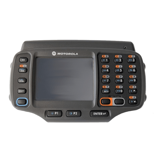
Chapter 1 Getting Started Introduction This chapter lists the accessories for the wearable terminal and explains how to install and charge the batteries and start the wearable terminal for the first time. Unpacking the Wearable Terminal Carefully remove all protective material from around the wearable terminal and save the shipping container for later storage and shipping. - Page 22 1 - 2 WT4070/90 Wearable Terminal Integrator Guide Power Button Display Charge Status LED Application Data Entry Keypad Keypad Speaker Action Keypad WT4070/90 Wearable Terminal Front View Figure 1-1 Application Controlled LED Battery Status LED WLAN Status LED Power Button...
- Page 23 Getting Started 1 - 3 Interface Connector Rubber Plug Battery Battery Release Cleat Interface Connector Cradle Connector (shown without Rubber Plug) Wearable Terminal Back View Figure 1-3 Parts of the Wearable Terminal Table 1-1 Item Description Display Displays the application and data stored on the device. (WT470/090 only) Power Button Places the wearable terminal in to the suspend mode or resumes normal operation.
-
Page 24: Getting Started
1 - 4 WT4070/90 Wearable Terminal Integrator Guide Getting Started In order to start using the wearable terminal for the first time: • Install the main battery • Charge the main battery and backup battery • Start the wearable terminal. -
Page 25: Charging The Battery
Getting Started 1 - 5 Charging the Battery Ensure that you follow the guidelines for battery safety described in Battery Safety Guidelines on page CAUTION 10-3. Charging the Main Battery and Memory Backup Battery Before using the wearable terminal for the first time, charge the main battery until the amber Charge Status LED remains lit (see Table 1-2 on page 1-5 for charge status indications). -
Page 26: Charging Spare Batteries
1 - 6 WT4070/90 Wearable Terminal Integrator Guide Charging Spare Batteries Use the following accessories to charge spare batteries: • Single Slot USB cradle • Four Slot Spare Battery charger. To charge a spare battery: Ensure the accessory used to charge the spare battery is connected to the appropriate power source. -
Page 27: Starting The Wearable Terminal
WT4070/90 Boot Up When the WT4070/90 is powered on for the first time the splash screen appears for a short period of time followed by the Start Up window on non-touch configurations and the calibration screen on touch enabled configurations. -
Page 28: Configuring The Wearable Terminal
NOTE Any data previously synchronized with a computer can be restored during the next ActiveSync operation. To perform a cold boot on a WT4070/90 press and simultaneously hold the Power button and the keys. Do not hold down any other keys or buttons. The wearable terminal initializes. -
Page 29: Changing The Power Settings
Turn off all wireless radio activity when not in use. Changing the Power Settings NOTE To navigate using the keypad refer to the WT4070/90 Wearable Terminal User Guide. To set the wearable terminal to turn off after a short period of non-use: Select >... -
Page 30: Turning The Wlan Radios Off
Disable keylight Press ENTER Turning the WLAN Radios Off NOTE To navigate using the keypad refer to the WT4070/90 Wearable Terminal User Guide. To turn off the WLAN radio: Press . The Wireless menu appears. Select... -
Page 31: Chapter 2 Accessories
Chapter 2 Accessories Introduction Wearable terminal accessories provide a wide variety of product support capabilities. Accessories include cradles, a battery charger, scanners and headsets. For all accessories not covered in this chapter, refer to the WT4070/90 Wearable Terminal User Guide. Cradles •... -
Page 32: Single Slot Usb Cradle
Use only an approved power supply output rated 12 VDC and minimum 3.3 A. Use of an alternative CAUTION power supply will void the product warranty and may cause product damage. Refer to the WT4070/90 User Guide for the power supply regulatory compliance statement. - Page 33 Accessories 2 - 3 USB A Male USB Port Power Port AC Line Cord USB Port Power Supply DC Cable Mini USB B USB Cable Single Slot USB Cradle Setup Figure 2-1...
-
Page 34: Battery Charging Indicators
2 - 4 WT4070/90 Wearable Terminal Integrator Guide Spare Battery Charge Status LED Wearable Terminal and Spare Battery Charging Figure 2-2 Battery Charging Indicators The Single Slot USB cradle can charge the wearable terminal’s main battery and a spare battery simultaneously. -
Page 35: Communication Setup
Accessories 2 - 5 Communication Setup The wearable terminal can communicate with a host computer using the Single Slot USB cradle. By default the wearable terminal is configured to communicate using USB. Ensure that ActiveSync on the host computer is set to allow USB connections. -
Page 36: Four Slot Ethernet Cradle
Use only an approved power supply output rated 12 VDC and minimum 9 A. Use of an alternative CAUTION power supply will void the product warranty and may cause product damage. See the WT4070/90 User Guide for the power supply regulatory compliance statement. -
Page 37: Daisychaining Cradles
Accessories 2 - 7 Power Port Ethernet Port 1 AC Line Cord Power Supply Ethernet Switch Ethernet Cable DC Power Cable Connection Four Slot Ethernet Cradle Setup Figure 2-5 Daisychaining Cradles To connect several cradles to an Ethernet network, up to four Ethernet cradles may be daisychained. Daisy-chaining should not be attempted when the main Ethernet connection to the first cradle is 10 Mbps as throughput issues will certainly result. -
Page 38: Ethernet Cradle Drivers
Four Slot Ethernet cradle, the LAN icon appears in the Windows CE 5.0 desktop taskbar and indicates that the wearable terminal is connected to a network. NOTE The device’s IP address can only be viewed on the WT4070/90. To view the IP Address assigned to the wearable terminal open a window and enter ipconfig . -
Page 39: Charging And Communication
Accessories 2 - 9 Use the navigation keys to select Programs Press to open the sub-menu. ENTER Use the navigation keys to select Command Prompt Press . The window displays. ENTER Command Prompt Enter ipconfig . The window displays the IP Address assigned to the wearable terminal. Ethernet IP Address Figure 2-7 Charging and Communication... -
Page 40: Battery Charging Indicators
2 - 10 WT4070/90 Wearable Terminal Integrator Guide Battery Charging Indicators The wearable terminal’s amber Charge Status LED shows the status of the battery charging in the wearable terminal. See Table 1-2 on page 1-5 for charging status indications. The standard capacity battery usually charges in less than four hours and the extended capacity battery usually charges in less than eight hours. -
Page 41: Four Slot Spare Battery Charger
Use only an approved power supply output rated 12 VDC and minimum 3.3 A. Use of an alternative power CAUTION supply will void the product warranty and may cause product damage. Refer to the WT4070/90 User Guide for the power supply regulatory compliance statement. -
Page 42: Battery Charging Indicators
2 - 12 WT4070/90 Wearable Terminal Integrator Guide Battery Charging Indicators Each battery charging well has an amber Spare Battery Charge Status LED. (see Figure 2-10 on page 2-11). See Table 2-2 for charging status indications. The standard capacity battery usually charges in less than four hours and the extended capacity battery usually charges in less than eight hours. -
Page 43: Wall Mount Bracket
Accessories 2 - 13 Wall Mount Bracket Use the wall mounting bracket to mount a Four Slot Ethernet cradle and a Four Slot Battery Charge together on a wall. To mark the screw holes for mounting the bracket use the wall mounting bracket as a template. Place the bracket onto the wall, level and mark the five screw hole locations. -
Page 44: Power Supply Installation
2 - 14 WT4070/90 Wearable Terminal Integrator Guide Power Supply Installation Place power supply onto mounting shelf with the DC output connector and fan facing out and with the fan on top. Power Supply Fan DC Output Connector Power Supply... -
Page 45: Four Slot Ethernet Cradle Installation
Accessories 2 - 15 Four Slot Ethernet Cradle Installation Align the two slots in the back of the cradle with the two cradle alignment tabs on the bracket. Cradle Slots Cradle Alignment Tab Aligning the Slots in the Cradle with Mounting Bracket Tabs Figure 2-13 Secure the cradle to the mounting bracket with two M4.0 screws supplied with the bracket. - Page 46 2 - 16 WT4070/90 Wearable Terminal Integrator Guide Securing the Four-Slot Ethernet Cradle to the Mounting Bracket Figure 2-14...
-
Page 47: Four Slot Battery Charger Installation
Accessories 2 - 17 Four Slot Battery Charger Installation The Four Slot Spare Battery Charger has four mounting slots on the back. Around the slots are guides that assist in proper alignment of the charger onto the mounting bracket. Gravity holds the charger in place. Mounting Slots Mounting Studs Installing the Battery Charger onto the Mounting Bracket... - Page 48 2 - 18 WT4070/90 Wearable Terminal Integrator Guide Cradle Power Plug Ethernet Cable Plug Right Cable Slot Charger Tie-Wraps Power Plug Cable Routing Figure 2-16 Use one tie-wrap to secure the AC line cord and Ethernet cable to the mounting bracket.
-
Page 49: Placing A Battery In The Charger
Accessories 2 - 19 Placing a Battery in the Charger When placing a spare battery into the Four Slot Spare Battery Charger, ensure proper orientation of the battery. Inserting a Battery into the Battery Charger Figure 2-18 Mounting Multiple Brackets When installing multiple brackets on a wall: •... - Page 50 2 - 20 WT4070/90 Wearable Terminal Integrator Guide 25.4 cm Position Tabs 10 in. Together to Ensure Minimum Distance 61 cm 24 in. Installing Multiple Mounting Brackets Figure 2-19...
-
Page 51: Navigating The Wearable Terminal With An External Input Device
Accessories 2 - 21 Navigating the Wearable Terminal with an External Input Device To assist in development, an external input device, such as a mouse, can be used to navigate the desktop and applications instead of using the wearable terminal keypad. •... - Page 52 2 - 22 WT4070/90 Wearable Terminal Integrator Guide USB Keyboard Mini USB A USB A Female USB Cable USB Keyboard Connection to the Single Slot USB Cradle Figure 2-21 USB Keyboard USB Mouse Mini USB A USB Cable USB Hub...
-
Page 53: Bluetooth Mouse
Accessories 2 - 23 Bluetooth Mouse NOTE The following procedures assume that you are using the wearable terminal keypad. Use these procedures for OEM version 04.20.0004 and below. For OEM version 05.30.0000 and above, see Chapter 6, Using Bluetooth for more information on using the BTExplorer application. -
Page 54: Connector Shroud
2 - 24 WT4070/90 Wearable Terminal Integrator Guide Connector Shroud Assembly Remove cable from wearable terminal, if required. Align the cable connector with the connector shroud bottom housing. Ensure that the disconnect button on the connector faces up. Disconnect Button... - Page 55 Accessories 2 - 25 Connector Eject Hole Disconnecting Connector with Shroud Figure 2-25...
- Page 56 2 - 26 WT4070/90 Wearable Terminal Integrator Guide...
-
Page 57: Chapter 3 Activesync
Chapter 3 ActiveSync Introduction To communicate with various host devices, install Microsoft ActiveSync (version 4.1 or higher) on the host computer. Use ActiveSync to synchronize information on the wearable terminal with information on the host computer. Changes made on the wearable terminal or host computer appear in both places after synchronization. ActiveSync software: •... -
Page 58: Wearable Terminal Setup
3 - 2 WT4070/90 Wearable Terminal Integrator Guide Wearable Terminal Setup NOTE Microsoft recommends installing ActiveSync on the host computer before connecting the wearable terminal. The wearable terminal is set by default to communicate using a USB connection. Chapter 2, Accessories provides the accessory setup and cable connection information for use with the wearable terminal. -
Page 59: Setting Up A Partnership
ActiveSync 3 - 3 Connection Settings Window Figure 3-2 Select check box. Allow USB connections Select the check box. Show status icon in Taskbar Select to save any changes made. Setting up a Partnership To set up a partnership: If the window does not appear on the host computer, select >... - Page 60 3 - 4 WT4070/90 Wearable Terminal Integrator Guide Select Synchronization Setting Window Figure 3-4 Select the appropriate settings and click Next Setup Complete Window Figure 3-5 Click Finish...
- Page 61 ActiveSync 3 - 5 WT4090 ActiveSync Connected Window Figure 3-6 During the first synchronization, information stored on the wearable terminal is copied to the host computer. When the copy is complete and all data is synchronized, the wearable terminal can be disconnected from the host computer.
- Page 62 3 - 6 WT4070/90 Wearable Terminal Integrator Guide...
-
Page 63: Chapter 4 Voice Only Wt4090 Remote Control
Chapter 4 Voice Only WT4090 Remote Control Introduction Since the Voice Only WT4090 does not have a display, access to settings and controls must be done using a remote display software, such as MotoRC or ActiveSync Remote Display. MotoRC Software Download the MotoRC application from the Zebra Support Central web site: http://www.zebra.com/support. -
Page 64: Motorc Connection
4 - 2 WT4070/90 Wearable Terminal Integrator Guide MotoRC Connection To control the Voice Only WT4090 using the MotoRC software: On the host computer, click Start > Programs > MSP > MotoRC > Run Remote Control. The Run Remote Control DOS window opens followed by the Remote Control window. -
Page 65: Microsoft Activesync Remote Display Connection
ActiveSync 4 - 3 Remote Control Window with Voice Only WT4090 Desktop Figure 4-2 Use the host computer mouse to control the Voice Only WT4090 desktop. When finished, close the Remote Control and Run Remote Control windows. Microsoft ActiveSync Remote Display Connection To control the Voice Only WT4090 using the Microsoft ActiveSync Remote Display software: On the host computer, click Start >... - Page 66 4 - 4 WT4070/90 Wearable Terminal Integrator Guide...
-
Page 67: Chapter 5 Wireless Applications
Chapter 5 Wireless Applications Introduction NOTE This chapter described Fusion versions below 2.55. For Fusion versions 2.55 and above, refer to the Wireless Fusion Enterprise Mobility Suite User Guide for Version X.XX User Guide for information, where X.XX represents the Fusion version number. These guides are available on the Zebra Support Central web site: http://www.zebra.com/support. -
Page 68: Signal Strength Icon
5 - 2 WT4070/90 Wearable Terminal Integrator Guide Wireless Applications Menu Figure 5-1 Signal Strength Icon icon in the task tray indicates the wearable terminal’s wireless signal strength as follows: Signal Strength Wireless Applications Icons, Signal Strength Descriptions Table 5-1... -
Page 69: Turning The Wlan Radio On And Off
Wireless Applications 5 - 3 Turning the WLAN Radio On and Off To turn off the WLAN radio: Press . The Wireless menu appears. Using the navigation keys, select Disable Radio Press ENTER To turn on the radio: Press . The Wireless menu appears. Using the navigation keys, select Enable Radio Press... -
Page 70: Profile Editor Wizard
5 - 4 WT4070/90 Wearable Terminal Integrator Guide Signal Strength Icon Table 5-2 Icon Description Excellent signal Very good signal Good signal Fair signal Poor signal Out of range or no signal Encryption Icon Table 5-3 Icon Description No encryption. WLAN is an infrastructure network. -
Page 71: Operating Mode
Wireless Applications 5 - 5 Profile ID Dialog Box Figure 5-3 Profile ID Fields Table 5-4 Field Description Name The name and (WLAN) identifier of the network connection. Enter a user friendly name for the wearable terminal profile used to connect to either an AP or another networked computer. Example: The Public LAN. - Page 72 5 - 6 WT4070/90 Wearable Terminal Integrator Guide Operating Mode Fields Table 5-5 Field Description Operating Mode Select to enable the wearable terminal to transmit and receive data with an Infrastructure AP. Infrastructure is the default mode. Select to enable the wearable terminal to form its own local network where Ad Hoc wearable terminals communicate peer-to-peer without APs using a shared ESSID.
-
Page 73: Ad-Hoc
Wireless Applications 5 - 7 Ad-Hoc Use the dialog box to select the required information to control mode. This dialog box does not Ad-Hoc Ad-Hoc appear if you selected mode. To select Ad-Hoc mode: Infrastructure Press to highlight the drop-down list. Channel Use the navigation keys to select a channel number. -
Page 74: Tunneled Authentication
5 - 8 WT4070/90 Wearable Terminal Integrator Guide Authentication Dialog Box Figure 5-6 Authentication Options Table 5-6 Authentication Description None Default setting when authentication is not required on the network. TLS (Fusion 2.4) Select this option to enable EAP-TLS authentication. EAP-TLS is an authentication EAP-TLS (Fusion 2.5) - Page 75 Wireless Applications 5 - 9 Press . The dialog box appears. ENTER Installed User Certificates Table 5-7 lists the PEAP tunneled authentication options. PEAP Tunneled Authentication Options Table 5-7 PEAP Tunneled Description Authentication MS CHAP v2 Microsoft Challenge Handshake Authentication Protocol version 2 (MS CHAP v2) is a password-based, challenge-response, mutual authentication protocol that uses the industry-standard Message Digest 4 (MD4) and Data Encryption Standard (DES) algorithms to encrypt responses.
-
Page 76: User Certificate Selection
5 - 10 WT4070/90 Wearable Terminal Integrator Guide TTLS Tunneled Authentication Options (Continued) Table 5-8 TTLS Tunneled Description Authentication MS CHAP v2 MS CHAP v2 is a password based, challenge response, mutual authentication protocol that uses the industry standard Message Digest 4 (MD4) and Data Encryption Standard (DES) algorithms to encrypt responses. -
Page 77: Server Certificate Selection
Wireless Applications 5 - 11 ********* Credentials Dialog Box Figure 5-9 Enter the (password), and information in their respective text boxes. Press to move to User: Pwd: Server: each field. Press to highlight the Retrieve button. Press dialog indicates the status of the certificate retrieval. ENTER Progress Press... -
Page 78: Credential Cache Options
5 - 12 WT4070/90 Wearable Terminal Integrator Guide Browse Server Certificates Figure 5-11 Navigate to the folder where the certificate is stored. Select the certificate filename and then select ok. A confirmation dialog verifies the installation. If the information in this dialog is correct, select the Yes button, If the information in this dialog is not correct select the button. - Page 79 Wireless Applications 5 - 13 caching options require the wearable terminal to prompt for new credentials. If you entered the credentials via the profile, the wearable terminal does not prompt for new credentials. Table 4-9 lists the caching options. Cache Options Table 5-9 Description At Connect...
-
Page 80: User Name
5 - 14 WT4070/90 Wearable Terminal Integrator Guide At Time Dialog Box Figure 5-15 Enter the time using the 24 hour clock format in the box. (hh:mm) Press to highlight the button. > Press . to move the time to the right text box. Repeat for additional time periods. -
Page 81: Advanced Identity
Wireless Applications 5 - 15 Password Dialog Box Figure 5-17 Enter a password in the field. Password Press to highlight the check box. Advanced ID Press > (SPACE) to select the check box, if advanced identification is required. BKSP Advanced ID Press twice to highlight the button. - Page 82 5 - 16 WT4070/90 Wearable Terminal Integrator Guide Press Use the navigation keys to select a key index number. Press Press > (SPACE) to select the check box. BKSP Use Passkey Press twice to highlight the button. Next Press ENTER...
-
Page 83: Key Entry Page
Wireless Applications 5 - 17 Encryption / Authentication Matrix Table 5-11 Encryption Authentication Open TKIP (Fusion 2.5 only) None EAP TLS PEAP LEAP TTLS Key Entry Page If you select either the wizard proceeds to the key entry dialog box unless the 40-Bit WEP 128-Bit WEP check box was selected in the... -
Page 84: Ip Address Entry
5 - 18 WT4070/90 Wearable Terminal Integrator Guide Passkey Dialog Box Figure 5-21 Enter the passkey in the text box. Passkey Press twice to highlight the button. Next Press . The dialog box displays. ENTER IP Address Entry IP Address Entry... - Page 85 Wireless Applications 5 - 19 Static IP Address Entry Dialog Box Figure 5-23 Enter the IP address in the text box. IP Address Press Enter the subnet mask address in the text box. Subnet Mask Static IP Address Entry Fields Table 5-13 Field Description...
-
Page 86: Transmit Power
5 - 20 WT4070/90 Wearable Terminal Integrator Guide IP Config Advanced Address Entry Fields Table 5-14 Field Description The default gateway forwards IP packets to and from a remote destination. The Domain Name System (DNS) is a distributed Internet directory service. DNS translates domain names and IP addresses, and controls Internet email delivery. -
Page 87: Battery Usage
Wireless Applications 5 - 21 Transmit Power Dialog Box (Ad-Hoc Mode) Figure 5-26 Power Transmit Options (Ad-Hoc Mode) Table 5-16 Field Description Full Select power for the highest transmission power level. Select power when operating in Full Full highly reflective environments and areas where other devices could be operating nearby, or when attempting to communicate with devices at the outer edge of a coverage area. -
Page 88: Manage Profiles Application
5 - 22 WT4070/90 Wearable Terminal Integrator Guide Battery Usage Options Table 5-17 Field Description Continuous Aware Mode ( ) provides the best network performance, but yields the shortest battery life. Fast Power Save (the default) performs in the middle of CAM and MAX Power Save Fast Power Save with respect to network performance and battery life. -
Page 89: Changing Profiles
Wireless Applications 5 - 23 Profile Icons (Continued) Table 5-18 Icon Description Profile is in use and describes an ad-hoc profile not using encryption. Profile is in use and describes an ad-hoc profile using encryption. Profile is not valid in the device current operating regulatory domain. The profiles are listed in priority order for use by the automatic roaming feature. -
Page 90: Creating A New Profile
5 - 24 WT4070/90 Wearable Terminal Integrator Guide profile. Use the to edit the profile power consumption and security parameters. See Profile Editor Profile Wizard Wizard on page 4-6. Creating a New Profile To create new profiles from the window, press... -
Page 91: Wireless Status Application
Wireless Applications 5 - 25 If required, change the name in the field and select . A confirmation dialog box appears after the export Name Save completes. Wireless Status Application To open the window, press , select and press . The Wireless Status Wireless Status ENTER... - Page 92 5 - 26 WT4070/90 Wearable Terminal Integrator Guide Signal Strength Window Figure 5-34 After viewing the window, press to return to the window. Signal Strength Wireless Status Signal Strength Status Table 5-19 Field Description Signal Displays the Relative Signal Strength Indicator (RSSI) of the signal transmitted between the AP and wearable terminal.
-
Page 93: Current Profile Window
Wireless Applications 5 - 27 Signal Strength Status (Continued) Table 5-19 Field Description Association Count Displays the number of APs the wearable terminal connects to while roaming. AP MAC Address Displays the MAC address of the AP to which the wearable terminal is connected. Transmit Rate Displays the current rate of the data transmission. - Page 94 5 - 28 WT4070/90 Wearable Terminal Integrator Guide To open the window, press IPv4 Status IPv4 Status Window Figure 5-36 IPv4 Status Fields Table 5-21 Field Description IP Type Displays the IP type for the current profile: . If the IP type is DHCP, leased IP...
-
Page 95: Wireless Log Window
Wireless Applications 5 - 29 Wireless Log Window window displays a log of recent activity, such as authentication, association, and DHCP renewal Wireless Log completion, in time order. Save the log to a file or clear the log (within this instance of the application only). The auto-scroll feature automatically scrolls down when new items are added to the log. -
Page 96: Wireless Diagnostics Application
5 - 30 WT4070/90 Wearable Terminal Integrator Guide Versions Window Figure 5-38 The window displays software version numbers for the following: • Configuration Editor (Fusion 2.4 only) • Fusion Build • Public API • LoginService • Photon10 • WCCConfigEd (Fusion 2.5 only) •... -
Page 97: Icmp Ping Window
Wireless Applications 5 - 31 • ICMP Ping - tests the wireless network connection. • Trace Route - tests a connection at the network layer between the wearable terminal and any place on the network. • Known APs - displays the APs in range using the same ESSID as the wearable terminal. •... -
Page 98: Known Aps Window
5 - 32 WT4070/90 Wearable Terminal Integrator Guide Trace Route Window Figure 5-41 Enter an IP address or a DNS Name in the combo box. Press to highlight . Press . The Start Test Blue BKSP IP combo box should match the information shown in the window’s IP combo box. -
Page 99: Options
Wireless Applications 5 - 33 • The wearable terminal roams to a new profile • The wearable terminal suspends • The wearable terminal resets (warm or cold). Select to allow the wearable terminal to roam to any AP with a better signal. These settings are Set Roaming temporary and never saved to the registry. -
Page 100: Regulatory Options
5 - 34 WT4070/90 Wearable Terminal Integrator Guide check boxes are selected by default. To select/de-select the checkboxes, AP Networks Ad-Hoc Networks press to highlight a checkbox. Press to select or de-select the checkbox. Blue BKSP OP Mode Filtering Options... -
Page 101: Band Selection
Wireless Applications 5 - 35 Band Selection settings identify the frequency bands to scan when finding WLANs. These values refer to the Band Selection 802.11 standard networks. NOTE Select one band for faster access when scanning for WLANs. Band Selection Dialog Box Figure 5-45 Band Selection Options Table 5-25... -
Page 102: Change Password
5 - 36 WT4070/90 Wearable Terminal Integrator Guide System Options Table 5-26 Field Description Profile Roaming Configures the wearable terminal to roam to the next available WLAN profile when it moves out of range of the current WLAN profile. Enable IP Mgmt Enables the Wireless Companion Services to handle IP address management. -
Page 103: Export
Wireless Applications 5 - 37 Export NOTE Exporting options enables settings to persists after cold boot. to export all profiles to a registry file, and to export the options to a registry file. Export Options - Export Dialog Box Figure 5-48 To export options: Select and press... -
Page 104: Persistence
5 - 38 WT4070/90 Wearable Terminal Integrator Guide Selecting saves the current profile. This information is used to determine which profile to connect Export All Profiles with after a warm boot or cold boot. Persistence Export options and profiles to provide cold boot persistence for Windows CE 5.0 devices. Save the exported... -
Page 105: Log On/Off Application
Wireless Applications 5 - 39 Log On/Off Application When the user launches the application, the wearable terminal may be in two states; the user may be Log On/Off logged onto the wearable terminal by already entering credentials through the login box, or there are no user logged on. - Page 106 5 - 40 WT4070/90 Wearable Terminal Integrator Guide Log On/Off Options (Continued) Table 5-28 Field Description Network Username and fields are used as credentials for the Network Username Network Password Password Fields profile selected in the field. Currently these fields are limited to 159 Wireless Profile characters.
-
Page 107: Chapter 6 Using Bluetooth
Chapter 6 Using Bluetooth Introduction NOTE The VOWT4090 requires the use of a Remote Desktop software to configure settings and software. See for information on setting up the device with remote desktop software. Bluetooth-equipped devices can communicate without wires, using frequency-hopping spread spectrum (FHSS) RF to transmit and receive data in the 2.4 GHz Industry Scientific and Medical (ISM) band (802.15.1). -
Page 108: Security
6 - 2 WT4070/90 Wearable Terminal Integrator Guide When AFH is enabled, the Bluetooth radio “hops-around” (instead of through) the 802.11b high-rate channels. AFH coexistence allows Zebra wearable terminals to operate in any infrastructure. AFH is always enabled in the WT4090. -
Page 109: Turning The Bluetooth Radio Mode On And Off
Using Bluetooth 6 - 3 Turning the Bluetooth Radio Mode On and Off NOTE Turning the Bluetooth radio on and off using the following procedures is only available on OEM version 05.30.0000 and higher. Earlier OEM versions use StoneStreet API commands to turn the Bluetooth radio on and off. -
Page 110: Bluetooth Power States
6 - 4 WT4070/90 Wearable Terminal Integrator Guide Bluetooth Power States Cold Boot When a cold boot is performed on the wearable terminal, Bluetooth turns off. It is normal to see the Bluetooth icon appear and disappear, as well as a wait cursor, when initialization proceeds in all modes. - Page 111 Using Bluetooth 6 - 5 The ProfileSelector window appears. Bluetooth Profile Selector Window Figure 6-3 NOTE The Serial Port profile is always active and cannot be removed. Use the navigation keys to highlight a profile. Press the SPACE key to select the profile. or press TAB to place focus on the Select All button to select all profiles or the Deselect All button to deselect all profiles.
-
Page 112: Accessing Btexplorer
Blue key - up arrow Right arrow Blue key - down arrow Refer to the WT4070/90 Wearable Terminal User Guide for detailed information on keypad navigation. Key Combinations The wearable terminal uses special key combinations to easily navigate applications. Table 6-2 lists the key combinations required to perform various application navigation and control functions. -
Page 113: Discovering Bluetooth Device(S)
Using Bluetooth 6 - 7 Key Combinations Table 6-2 Action Combination Access the Start menu on the taskbar CTRL - ESC Switch fields within an application Close windows or cancel operations on some applications ALT - F4 Access the Task Manager ALT - TAB Switches to the next window or desktop ALT - ESC... - Page 114 6 - 8 WT4070/90 Wearable Terminal Integrator Guide New Connection Wizard Window Figure 6-5 Use the navigation keys to select Explore Services on Remote Device. The following actions are available in the drop-down list (actions may vary depending upon configurations): •...
- Page 115 Using Bluetooth 6 - 9 NOTE To filter devices in the list press ALT - F to open the filter menu. Select a device type and then press ENTER. To change the display view press ALT - V to open the view menu. Select a view type and then press ENTER. Select Remote Device Window Figure 6-7 Use the navigation keys to select a device from the list and press ENTER.
-
Page 116: Available Services
6 - 10 WT4070/90 Wearable Terminal Integrator Guide Connection Summary Window Figure 6-10 Press P2 to add the service to the Favorite window. The Favorite window appears and the wearable terminal connects to the remote device. Favorite Window with Active Connection... -
Page 117: Create New File Or Folder
Using Bluetooth 6 - 11 Press ENTER. The File Transfer window appears listing the folders of the remote device. File Transfer Window Figure 6-12 Use the navigation keys to select a file. To open a folder press ENTER. Press ENTER to copy the file from the remote device. The Save Remote Device window appears. Save Remote File Window Figure 6-13 Press TAB three times to enter the folder area. -
Page 118: Delete File
6 - 12 WT4070/90 Wearable Terminal Integrator Guide Press the right arrow to open the sub-menu. Use the navigation keys to select Folder or File. Press ENTER. The Create New Folder or Create New File window appears. Create New Folder Window Figure 6-14 Enter a new name for the new folder or file and then press ENTER. -
Page 119: Put File
Using Bluetooth 6 - 13 Press TAB three times to enter the folder area. Using the navigation keys to highlight a folder and press ENTER. The OBEX Object Push window appears. Press ENTER. The file is transferred from the remote device to the wearable terminal. Put File To copy a file from the wearable terminal to a remote device: In the File Transfer window, navigate to a folder where the file will be put into. -
Page 120: Obex Object Push Services
6 - 14 WT4070/90 Wearable Terminal Integrator Guide Press ENTER. The wearable terminal connects with the Access Point. Press CTRL - ESC to open the Start menu. Use the navigation keys to select Internet Explorer. Press ENTER. The Internet Explorer window appears. -
Page 121: Headset Services
Using Bluetooth 6 - 15 Press ENTER. The wearable terminal connects to the remote device and begins to send the file. The Sending Picture window appears. When the file transfer is complete a confirmation dialog appears. Press ENTER. Sending Picture Window Figure 6-20 Headset Services To connect to a Bluetooth headset:... -
Page 122: Personal Area Network Services
6 - 16 WT4070/90 Wearable Terminal Integrator Guide Remote Service Connection Window Figure 6-21 In the Local COM Port drop-down list select a COM port. Press ENTER. Personal Area Network Services Connect two or more Bluetooth devices to share files and collaborate. -
Page 123: Bonding With Discovered Device(S)
Using Bluetooth 6 - 17 Bonding with Discovered Device(s) A bond is a relationship created between the wearable terminal and another Bluetooth device in order to exchange information in a secure manner. Creating a bond involves entering the same PIN on the two devices to bond. Once a bond is created, and the Bluetooth radios are turned on, the devices recognize the bond and are able to exchange information without re-entering a PIN. -
Page 124: Accepting A Bond
6 - 18 WT4070/90 Wearable Terminal Integrator Guide NOTE To filter devices in the list press ALT - F to open the filter menu. Select a device type and then press ENTER. To change the display view press ALT - V to open the view menu. Select a view type and then press ENTER. -
Page 125: Trusted Devices Window
Using Bluetooth 6 - 19 PIN Code Request Window Figure 6-26 NOTE Connections to untrusted devices are a security risk. In the PIN Code: text box, enter the same PIN that was entered on the device requesting the bond. The PIN must be between 1 and 16 characters. -
Page 126: Deleting A Bonded Device
6 - 20 WT4070/90 Wearable Terminal Integrator Guide Trusted devices Window Menu Figure 6-28 Use the navigation keys to select a view type and then press ENTER. Deleting a Bonded Device If it is no longer necessary to connect with a device, delete it from the Bluetooth Trusted Devices window. -
Page 127: Navigating The Favorites Window
Using Bluetooth 6 - 21 Press MENU. Use the navigation keys to select Disconnect. Press ENTER. A deaconate confirmation dialog box appears. Select Yes to disconnect the service. The wearable computer disconnects from the service. Navigating the Favorites Window The Favorites window has three menus that can be accessed through key combinations. Favorites Window Menus Figure 6-30 To open the File menu, press ALT - F. -
Page 128: Rename A Favorite Service
6 - 22 WT4070/90 Wearable Terminal Integrator Guide Rename a Favorite Service To rename a favorite: Use the navigation keys to select a favorite. Press MENU. Use the down arrow key to select Rename. Press ENTER. The Change Device Name window appears. -
Page 129: Bluetooth Settings
Using Bluetooth 6 - 23 Bluetooth Settings Use the BTExplorer Settings window to configure the operation of the BTExplorer application. To access the settings, press ALT - T, use the navigation keys to select Settings. Press ENTER. The BTExplorer Settings window appears. -
Page 130: File Transfer Service
6 - 24 WT4070/90 Wearable Terminal Integrator Guide BTExplorer Settings - Services Tab Figure 6-32 To add a service: Press TAB to highlight the Add key. Press SPACE. The Add Local Service window displays. Add Local Service Window Figure 6-33 In the list, use the navigation key to select a service to add. -
Page 131: Obex Object Push Service
Using Bluetooth 6 - 25 File Transfer Information Window Table 6-4 Field Description Service Name Displays the name of the service. Service Security Select the type of security from the drop-down list; None, Authenticate or Authenticate/Encrypt. Root Directory Select the directory that other Bluetooth devices can access. File Permissions Select the file permissions for the selected directory. -
Page 132: Serial Port Service
6 - 26 WT4070/90 Wearable Terminal Integrator Guide Personal Area Networking Window Figure 6-36 Personal Area Networking Window Table 6-6 Field Description Service Name Displays the name of the service. Service Security Select the type of security from the drop-down list; None, Authenticate or Authenticate/Encrypt. -
Page 133: Headset Service
Using Bluetooth 6 - 27 Serial Port Service Window Table 6-7 Field Description Local COM Port Select the COM port. Select COM1 to use a modem or other device that is connected to the connector on the bottom of the wearable terminal. Local Baud Rate Select the communication baud rate. -
Page 134: Security Tab
6 - 28 WT4070/90 Wearable Terminal Integrator Guide Security Tab To adjust the security settings for an individual service, select the Services tab first, then select the individual service, then Properties. BTExplorer Settings - Security Tab Figure 6-40 Security Tab... -
Page 135: Virtual Com Port Tab
Using Bluetooth 6 - 29 BTExplorer Settings - Discovery Tab Figure 6-41 Discovery Tab Table 6-9 Field Description Inquiry Length Sets the amount of time that the wearable terminal takes to discover Bluetooth devices in the area. Name Discovery Mode Select either Automatic or manual. -
Page 136: Hid Tab
6 - 30 WT4070/90 Wearable Terminal Integrator Guide COM Port Connection Figure 6-43 HID Tab NOTE The HID tab only appears if HID is selected in the Bluetooth Profile Selector application. See Bluetooth Profiles on page 6-4 for more information. - Page 137 Using Bluetooth 6 - 31 Miscellaneous Tab Table 6-12 Field Description Highlight Connections Select the connection type to highlight when connected. In the Wizard Mode, the only option is Favorites or None. Apply Text Style Select the text style to be applied to the connection text. Apply Text Color Select the text color to be applied to the connection text.
- Page 138 6 - 32 WT4070/90 Wearable Terminal Integrator Guide...
-
Page 139: Chapter 7 Application Deployment
Device Configuration Package (DCP) for WT40x0. The EMDK for C is a development tool used to create native C and C++ applications for the WT4070/90. It includes documentation, header files (.H), and library files (.LIB) for native code application development that targets Zebra value-add APIs. -
Page 140: Platform Sdk
7 - 2 WT4070/90 Wearable Terminal Integrator Guide Once installed, access the major components of the DCP from the Device Configuration Package (DCP) for WT40x0 program group of the Windows Start Menu. Platform SDK Different Platform SDKs are required for the Microsoft® Windows CE 5.0 Professional and Microsoft® Windows CE 5.0 Core platforms. -
Page 141: Osupdate
When the Update Loader application finds the appropriate file, it loads the package onto the wearable terminal. NOTE On the WT4070/90, a progress bar displays until the update completes. On the Voice Only WT4090, as soon as OSUpdate starts, all three LEDs turn on and then the three LEDs indicate the progress of the download. -
Page 142: Ipl
7 - 4 WT4070/90 Wearable Terminal Integrator Guide ActiveSync Explorer Figure 7-1 Double-click the folder to expand the contents of the folder. My Pocket PC Contents Figure 7-2 Use Explorer to locate the host computer directory that contains the file to download. Tap that directory in the left pane to display its contents in the right pane. -
Page 143: Creating Hex Images
Application Deployment 7 - 5 previous file are erased. The operating system must be running for a file to be updated, so the IPL cannot perform individual file updates as it is a stand-alone program that does not require the operating system to be running. A typical partition is a group of files, combined into a single “partition”... -
Page 144: Starting Terminal Configuration Manager
7 - 6 WT4070/90 Wearable Terminal Integrator Guide • Creating the script for the hex image • Building the image • Sending the hex image • Creating a splash screen • Flash storage. Starting Terminal Configuration Manager Click the Windows start menu TCM icon (Device Configuration Packages, WT40x0c50) to start TCM. The window appears displaying two child windows: . -
Page 145: Defining Script Properties
Application Deployment 7 - 7 TCM Components (Continued) Table 7-1 Icon Component Function Save button Save the current script file. Large icons button View the current script items as large icon. Small icons button View the current script items as small icon. List button View the current script items as a list. -
Page 146: Creating The Script For The Hex Image
7 - 8 WT4070/90 Wearable Terminal Integrator Guide Script Properties Window - Partition Data Tab Figure 7-4 In the drop-down list, select the terminal type. Terminal Use the default Flash Type In the drop-down list, select the number of disk partitions to create. -
Page 147: Opening A New Or Existing Script
Application Deployment 7 - 9 The Script1 window directory pane displays two partitions: Platform and Application. Depending on the type of flash chip, the number of partitions may change. Files can be added to each of the partitions. TCM functionality includes: •... - Page 148 7 - 10 WT4070/90 Wearable Terminal Integrator Guide Configure Build Window Figure 7-7 Select the items (partitions) to build using the check box(es) to the left of each named partition. defines where to store all built partitions. Build Path Select (hex image) COMPRESSION to reduce the size and speed up the download.
-
Page 149: Sending The Hex Image Using Ipl
NOTE The wearable terminal must be inserted in the cradle with appropriate power supply connected to a power source, for the wearable terminal to reset into IPL. WT4070/90 Press the and Power button. The wearable terminal performs a cold boot. - Page 150 7 - 12 WT4070/90 Wearable Terminal Integrator Guide IPL Menu Partitions Table 7-2 Partition Name Description Platform Contains the files in the Platform folder. Application Contains the files in the Application folder. Windows CE Contains the operating system for the wearable terminal.
- Page 151 Application Deployment 7 - 13 Use the up and down scroll buttons to select and press . If this is the first time using USB transport, Enter you might need to install the Zebra USB driver. Follow the screen prompts. menu appears.
- Page 152 7 - 14 WT4070/90 Wearable Terminal Integrator Guide Download: “Partition Name” via USB USB Standard Press Enter to continue Parameters Screen Figure 7-12 is the name of the partition selected in the menu. Partition Name Initial Program Loader Press to return to the menu.
-
Page 153: Voice Only Wt4090
Application Deployment 7 - 15 Select the Image Files To Load In the Comm Port drop-down list, select USB: Symbol Device Click to begin the operation. Download During download, the screen on wearable terminal displays the and a progress bar. Downloading Device Status When complete,... -
Page 154: Tcm Error Messages
7 - 16 WT4070/90 Wearable Terminal Integrator Guide When complete, the message “Transfer Complete. Check the terminal for successful completion.” Click OK. Repeat steps 5 through 9 for each file to download. To exit IPL, perform a cold boot. TCM Error Messages TCM validates the cells in the partition table when the Execute button is clicked. -
Page 155: Ipl Error Detection
While receiving data, IPL performs many checks on the data to ensure that the data is received correctly. If an error is detected, IPL immediately aborts the download, and reports the error on an error screen on a WT4070/90 or with the LEDs on a Voice Only WT4090. - Page 156 7 - 18 WT4070/90 Wearable Terminal Integrator Guide This error message screen displays until you press any key. Once the screen is acknowledged, IPL returns to the main menu to wait for a new selection. Initial Program Loader To find the probable cause of the error, use the error number and/or the error text displayed on the screen to look...
-
Page 157: Voice Only Wt4090 Ipl Error Indications
Application Deployment 7 - 19 IPL Errors (Continued) Table 7-4 Error Error Text Probable Cause Number Exceeded max size The download file is too large to fit into the space allocated for it. Either make the file smaller or increase the space allocated for it by altering the partition table. -
Page 158: Flash Storage
7 - 20 WT4070/90 Wearable Terminal Integrator Guide If the default files are not used to create the new splash screens, be sure to preserve the image format. The formats are as follows: Splash Screen Format Table 7-5 Screen Type... -
Page 159: Regmerge.dll
Application Deployment 7 - 21 RegMerge.dll RegMerge.dll is a built-in driver that allows registry edits to be made to the Windows CE Registry. Regmerge.dll runs very early in the boot process and looks for registry files (.reg files) in certain Flash File System folders during a cold boot. -
Page 160: Non-Ffs Partitions
7 - 22 WT4070/90 Wearable Terminal Integrator Guide Non-FFS Partitions Non-FFS Partitions include additional software and data pre-loaded on the wearable terminal that can be upgraded. Unlike FFS Partitions, these partitions are not visible when the operating system is running. They also contain system information. -
Page 161: Chapter 8 Staging And Provisioning
Chapter 8 Staging and Provisioning Introduction The MSP 3 Client Software is a setof software components that come pre-installed on the wearable terminal. The MSP 3 Client software consists of the following three components: Refer to the Mobility Services Platform 3.2 User’s Guide, p/n 72E-100158-06, for instructions for using the Rapid Deployment, AirBEAM Smart and MSP3 Agent clients. - Page 162 8 - 2 WT4070/90 Wearable Terminal Integrator Guide...
-
Page 163: Chapter 9 Special Considerations
Chapter 9 Special Considerations Touch Panel User Interface Considerations When developing applications for a touch panel interface, touch panel activation only by the ball of the finger means there are limitations to what the user interface of an application can expect of a worker •... -
Page 164: Keypad Light
9 - 2 WT4070/90 Wearable Terminal Integrator Guide Ensure that the Disable backlight if not used for checkbox is checked. In the drop-down list, select the amount of time after which the display will turn off. Set to 1 minute or a lower value that the user is comfortable with. -
Page 165: Wireless Lan
Special Considerations 9 - 3 Select OK. Wireless LAN To set the WLAN radio to maximum performance: Select the wireless icon in the bottom lower right corner. Select Manage Profiles. Select your wireless profile, double click. Select Edit. Continuously select Next until the Battery Usage window appears. Ensure the MAX Power Save radio button is selected. - Page 166 9 - 4 WT4070/90 Wearable Terminal Integrator Guide...
-
Page 167: Chapter 10 Maintenance & Troubleshooting
Chapter 10 Maintenance & Troubleshooting Introduction This chapter includes instructions on cleaning and storing the wearable terminal, and provides troubleshooting solutions for potential problems during wearable terminal operating. Maintaining the Wearable Terminal For trouble-free service, observe the following tips when using the wearable computer: •... -
Page 168: Wrist Mount Cleaning Instructions
10 - 2 WT4070/90 Wearable Terminal Integrator Guide ® • Regularly replace all Velcro straps on the wrist mount and wearable scanners, to ensure adequate adhesion of the Velcro. • On touch screen versions, periodically replace the screen protector, especially if it is scratched. -
Page 169: Battery Safety Guidelines
Maintenance & Troubleshooting 10 - 3 Lift Screen Protector Corner Removing the Screen Protector Figure 10-2 Do not use a sharp object to remove the protector. Doing so can damage the touch screen. CAUTION Battery Safety Guidelines • The area in which the units are charged should be clear of debris and combustible materials or chemicals. Particular care should be taken where the device is charged in a non commercial environment. -
Page 170: Cleaning
10 - 4 WT4070/90 Wearable Terminal Integrator Guide • Seek medical advice immediately if a battery has been swallowed. • In the event of a battery leak, do not allow the liquid to come in contact with the skin or eyes. If contact has been made, wash the affected area with large amounts of water and seek medical advice. -
Page 171: Cleaning The Rs309, Rs409 And Rs507
Maintenance & Troubleshooting 10 - 5 Rub the cotton portion of the cotton tipped applicator back-and-forth across each connector. Do not leave any cotton residue on the connector. Repeat at least three times. Use the cotton tipped applicator dipped in alcohol to remove any grease and dirt near the connector area. Use a dry cotton tipped applicator and repeat steps 4 through 7. -
Page 172: Cleaning Frequency
10 - 6 WT4070/90 Wearable Terminal Integrator Guide Rub the cotton portion of the cotton tipped applicator along the pins of the connector. Slowly move the applicator back-and-forth from one side of the connector to the other. Do not let any cotton residue on the connector. - Page 173 Maintenance & Troubleshooting 10 - 7 Troubleshooting the Wearable Terminal (Continued) Table 10-1 Problem Cause Solution Rechargeable lithium-ion Battery failed. Replace battery. If the wearable terminal still does not operate, battery did not charge. try a warm boot, then a cold boot. See Resetting the Wearable Terminal on page 1-8.
- Page 174 10 - 8 WT4070/90 Wearable Terminal Integrator Guide Troubleshooting the Wearable Terminal (Continued) Table 10-1 Problem Cause Solution Wearable terminal turns Wearable terminal is The wearable terminal turns off after a period of inactivity. If the itself off. inactive. wearable terminal is running on battery power, this period can be set to 30 sec., 1, 2, 3, 4, 5 or 6 minutes.
- Page 175 Maintenance & Troubleshooting 10 - 9 Troubleshooting the Wearable Terminal (Continued) Table 10-1 Problem Cause Solution The wearable terminal Scanning application Verify that the unit is loaded with a scanning application. See does not accept scan is not loaded. the System Administrator. input.
-
Page 176: Four Slot Spare Battery Charger
10 - 10 WT4070/90 Wearable Terminal Integrator Guide Four Slot Spare Battery Charger Troubleshooting The Four Slot Spare Battery Charger Table 10-2 Symptom Possible Cause Solution Batteries not Battery was removed Re-insert the battery in the charger or re-connect the charger’s power charging. -
Page 177: Single Slot Usb Cradle
Maintenance & Troubleshooting 10 - 11 Troubleshooting the Four Slot Ethernet Cradle (Continued) Table 10-3 Problem Cause Solution During data communication, Wearable terminal removed Replace wearable terminal in cradle and no data was transmitted, or from cradle during retransmit. transmitted data was communication. - Page 178 10 - 12 WT4070/90 Wearable Terminal Integrator Guide Troubleshooting the Single Slot USB Cradle (Continued) Table 10-4 Symptom Possible Cause Action During data Wearable terminal Replace wearable terminal in cradle and retransmit. communications, removed from cradle no data was during communications.
-
Page 179: Appendix A: Technical Specifications
WT4070/90: Two-color Alphanumeric Keypad or Triple-tap Alphanumeric Keypad Voice Only WT4090: Three programmable function keys. Display WT4070/90: Color 2.8 inch QVGA non-touch or touch screens Voice Only WT4090: None Main Battery Removable, rechargeable 3.7 VDC Lithium Ion battery. Standard capacity: 2330 mAh (minimum) - Page 180 A - 2 WT4070/90 Wearable Terminal Integrator Guide Technical Specifications (Continued) Table A-1 Item Description Operating System Microsoft Windows CE 5.0 Professional Memory 64 MB Flash/128 MB RAM or 128 MB Flash/128 MB RAM Application Development PSDK, DCP and SMDK available through Zebra Developer Zone web site...
- Page 181 Specifications A - 3 Technical Specifications (Continued) Table A-1 Item Description Antenna Internal WPAN Wireless Data Communications Bluetooth Bluetooth Version 1.2...
-
Page 182: Rs309 Scanner
A - 4 WT4070/90 Wearable Terminal Integrator Guide Technical Specifications (Continued) Table A-1 Item Description Peripherals and Accessories Cradles Single Slot USB Four Slot Ethernet Printers Supports extensive line of Zebra approved printers, cables and accessories Charger Four Slot Battery Charger Other Accessories Headset adapter, freezer pouch, hip mount and wrist mount. -
Page 183: Rs409 Scanner
Specifications A - 5 RS309 Technical Specifications (Continued) Table A-2 Item Description Pitch ± 65 degrees from normal User Environment Operating Temperature -22 °F to 122 °F (-30 °C to 50 °C) Storage Temperature -40 °F to 140 °F (-40 °C to 60 °C) Humidity 5% to 95% non condensing Drop Specification... - Page 184 A - 6 WT4070/90 Wearable Terminal Integrator Guide RS409 Technical Specifications (Continued) Table A-3 Item Description Scan Rate 104 (± 12) scans/sec (bidirectional) Nominal Working Density 5 mil 7.5 mil 10 mil 13 mil 20 mil 40 mil 55 mil...
-
Page 185: Rs507 Scanner
Specifications A - 7 RS507 Scanner RS507 Technical Specifications Table A-4 Item Description Physical and Environmental Characteristics Dimensions Triggerless, standard battery: 2.9 x 5.3 x 7.4 cm (1.16 x 2.1 x 2.92 in.) Triggerless, extended battery: 3.6 x 5.3 x 7.4 cm (1.42 x 2.1 x 2.92 in.) Triggered, standard battery: 2.9 x 5.3 x 7.4 cm (1.16 x 2.1 x 2.92 in.) Triggered, corded (cord length not included): 3.3 x 5.3 x 7.4 cm (1.3 x 2.1 x 2.92 in.) Weight... - Page 186 A - 8 WT4070/90 Wearable Terminal Integrator Guide RS507 Technical Specifications (Continued) Table A-4 Item Description Supported Symbologies 1D enabled by default: Codabar, Code 39, Code 128, EAN-13, EAN-8, Interleaved 2 of 5, UPC-A and UPC-E. Additionally supported by 1D:...
-
Page 187: Accessories
Specifications A - 9 RS507 Technical Specifications (Continued) Table A-4 Item Description Environmental Sealing IP54 Electrostatic Discharge ±15kV air discharge, ±8kV direct discharge. (ESD) Power Cordless Standard battery: Li-Ion 970 mAh, 3.7 V with up to 35,000 scans (continuous) or up to 10 hours with 900 scans per hour on a single charge using fresh batteries. - Page 188 A - 10 WT4070/90 Wearable Terminal Integrator Guide Wearable Terminal Interface Connector Pin-Outs Pin 1 Pin Locations Figure A-1 Interface Connector Pin-Outs Table A-6 Signal Name Function SCANNER_DETECT_RIGHT Scanner detect. USBH_N_RIGHT USB host negative. Digital/system ground. USBH_P_RIGHT USB host positive.
- Page 189 Specifications A - 11 Pin 1 Cradle Connector Pin Locations Figure A-2 Cradle Connector Pin-Outs Table A-7 PIN Number Signal Name Function Power In 5.4 VDC input power. ACC_OTG_VBUS 5.0 VDC input in client mode, 5.0 VDC output in host mode. ACC_OTG_DP USB data positive.
- Page 190 A - 12 WT4070/90 Wearable Terminal Integrator Guide...
-
Page 191: Glossary
Glossary Numeric 802.11. A group of wireless specifications developed by the Institute of Electrical and Electronics Engineers (IEEE). It specifies an over-the-air interface between a wireless client and a base station or between two wireless clients. 802.11a. Operates in the 5 GHz frequency range (5.125 to 5.85 GHz) with a maximum 54Mbit/sec. signaling rate. The 5 GHz frequency band is not as crowded as the 2.4 GHz frequency because it offers significantly more radio channels than the 802.11b and is used by fewer applications. - Page 192 Glossary - 2 WT4070/90 Wearable Terminal Integrator Guide ANSI Terminal. A display terminal that follows commands in the ANSI standard terminal language. For example, it uses escape sequences to control the cursor, clear the screen and set colors. Communications programs support the ANSI terminal mode and often default to this terminal emulation for dial-up connections to online services.
- Page 193 Glossary - 3 CDRH Class 2. No additional software mechanisms are needed to conform to this limit. Laser operation in this class poses no danger for unintentional direct human exposure. CHAP. (Challenge Handshake Authentication Protocol) A type of authentication in which the authentication agent (typically a network server) sends the client program a random value that is used only once and an ID value.
- Page 194 Glossary - 4 WT4070/90 Wearable Terminal Integrator Guide Device Configuration Package. The Device Configuration Package provides flash partitions, Terminal Configuration Manager (TCM) and the associated TCM scripts. With this package hex images that represent flash partitions can be created and downloaded to the wearable terminal.
- Page 195 Glossary - 5 Hz. Hertz; A unit of frequency equal to one cycle per second. Host Computer. A computer that serves other terminals in a network, providing such services as computation, database access, supervisory programs and network control. IEC. International Electrotechnical Commission. This international agency regulates laser safety by specifying various laser operation classes based on power output during operation.
- Page 196 Glossary - 6 WT4070/90 Wearable Terminal Integrator Guide laser scanner. A type of bar code reader that uses a beam of laser light. LASER. (Light Amplification by Stimulated Emission of Radiation) The laser is an intense light source. Light from a laser is all the same frequency, unlike the output of an incandescent bulb.
- Page 197 Glossary - 7 NVM. Non-Volatile Memory. ODI. See Open Data-Link Interface. Open Data-Link Interface (ODI). Novell’s driver specification for an interface between network hardware and higher-level protocols. It supports multiple protocols on a single NIC (Network Interface Controller). It is capable of understanding and translating any network information or request sent by any other ODI-compatible protocol into something a NetWare client can understand and process.
- Page 198 Glossary - 8 WT4070/90 Wearable Terminal Integrator Guide RS-232. An Electronic Industries Association (EIA) standard that defines the connector, connector pins, and signals used to transfer data serially from one device to another. Scanner. An electronic device used to scan bar code symbols and produce a digitized pattern that corresponds to the bars and spaces of the symbol.
- Page 199 Glossary - 9 TCP/IP. (Transmission Control Protocol/Internet Protocol) A communications protocol used to internetwork dissimilar systems. This standard is the protocol of the Internet and has become the global standard for communications. TCP provides transport functions, which ensures that the total amount of bytes sent is received correctly at the other end. UDP is an alternate transport that does not guarantee delivery.
- Page 200 Wearable Terminal. In this text, wearable terminal refers to the WT4070/90 wireless portable computer. It can be set up to run as a stand-alone device, or it can be set up to communicate with a network, using wireless radio technology.
- Page 201 Index Numerics 128-Bit WEP ......5-15 backup battery 40-Bit WEP ....... 5-15 charging .
- Page 202 Index - 2 WT4070/90 Wearable Terminal Integrator Guide spare batteries ......1-6 Enterprise Mobility Developer Kit for eVC4 ..xvii temperature range .
- Page 203 Index - 3 parts of the wearable terminal ... 1-1, 1-2, 1-3 PassKey ........5-17 keyboard .
- Page 204 Index - 4 WT4070/90 Wearable Terminal Integrator Guide splash screen ......7-22 wireless status .
- Page 206 Zebra Technologies Corporation Lincolnshire, IL U.S.A. http://www.zebra.com Zebra and the stylized Zebra head are trademarks of ZIH Corp., registered in many jurisdictions worldwide. All other trademarks are the property of their respective owners. ©2015 ZIH Corp and/or its affiliates. All rights reserved. 72E-87638-07 Revision A - April 2015...