
Related Manuals for Planet Networking & Communication WGS3-24000


Summary of Contents for Planet Networking & Communication WGS3-24000
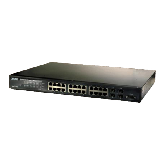
- Page 1 User's Manual WGS3-24000 24-Port 10/100/1000Mbps Layer 3 Managed Ethernet Switch...
-
Page 2: Fcc Warning
Do not dispose of WEEE as unsorted municipal waste and have to collect such WEEE separately. Revision PLANET 24-Port 10/100/1000Mbps with 4 Gigabit SFP Layer 3 Managed Ethernet Switch User's Manual FOR MODEL: WGS3-24000 REVISION: 1.1 (May.2007) Part No. EM-WGS3-24000_v1.1 (2081-A96020-001) -
Page 3: Table Of Contents
Table of Contents 1. INTRODUCTION........................19 1.1 Packet Contents ................................19 1.2 How to Use This Manual..............................19 1.3 Product Feature................................20 1.4 Product Specification ..............................22 2. INSTALLATION ........................24 2.1 Product Description ...............................24 2.1.1 Product Overview..............................24 2.1.2 Switch Front Panel............................25 2.1.3 LED Indications..............................25 2.1.4 Switch Rear Panel ............................25 2.2 Install the Switch................................26 2.2.1 Desktop Installation............................26... - Page 4 4.2.11 DHCP Server ..............................81 4.2.12 SNTP ................................89 4.3 Switching ..................................94 4.3.1 VLAN ................................94 4.3.2 Protocol-based VLAN .............................102 4.3.3 Port Security ..............................104 4.3.4 GARP................................110 4.3.5 IGMP Snooping............................... 113 4.3.6 Port Channel ..............................121 4.3.7 Multicast Forwarding Database........................125 4.3.8 Spanning Tree..............................128 4.3.9 Class of Service ..............................142 4.4 Security..................................143 4.4.1 Port Access Control ............................146 4.4.2 RADIUS ................................154...
- Page 5 4.7.6 PIM-SM................................301 5. COMMAND STRUCTURE ....................310 5.1 Format ..................................310 5.1.1 Command ...............................310 5.1.2 Parameters ..............................310 5.1.3 Values ................................310 5.1.4 Conventions ..............................311 5.1.5 Annotations ..............................311 6. QUICK START UP ......................312 6.1 Quick Starting the Switch.............................312 6.2 System Info and System Setup ...........................312 7.
- Page 6 8.4.2 show port-channel brief...........................333 8.5 Management Commands ............................333 8.5.1 bridge aging-time ............................333 8.5.2 mtu..................................334 8.5.3 network javamode............................334 8.5.4 network mac-address............................334 8.5.5 network mac-type............................334 8.5.6 network parms ..............................335 8.5.7 network protocol..............................335 8.5.8 remotecon maxsessions ..........................335 8.5.9 remotecon timeout ............................335 8.5.10 serial baudrate ..............................336 8.5.11 serial timeout..............................336 8.5.12 set prompt ..............................337 8.5.13 show forwardingdb agetime ..........................337...
- Page 7 8.6.4 delete interface ...............................345 8.6.5 deleteport................................346 8.6.6 macfilter ................................346 8.6.7 macfilter adddest.............................346 8.6.8 macfilter adddest all ............................347 8.6.9 macfilter addsrc...............................347 8.6.10 macfilter addsrc all ............................347 8.6.11 monitor session .............................348 8.6.12 monitor session mode...........................348 8.6.13 port lacpmode ...............................348 8.6.14 port lacpmode all............................349 8.6.15 port-channel ..............................349 8.6.16 port-channel adminmode ..........................349 8.6.17 port-channel linktrap .............................350...
- Page 8 8.6.44 show mac-address-table stats ........................360 8.6.45 show monitor ..............................360 8.6.46 show port ..............................360 8.6.47 show port protocol............................361 8.6.48 show port-channel............................361 8.6.49 show storm-control............................362 8.6.50 show vlan..............................362 8.6.51 show vlan brief ..............................363 8.6.52 show vlan port...............................363 8.6.53 shutdown ..............................364 8.6.54 shutdown all ..............................364 8.6.55 snmp trap link-status.............................364 8.6.56 snmp trap link-status all ..........................364 8.6.57 spanning-tree ..............................365...
- Page 9 8.7.4 users name ..............................373 8.7.5 users passwd ..............................373 8.7.6 users snmpv3 accessmode ..........................374 8.7.7 users snmpv3 authentication ..........................374 8.7.8 users snmpv3 encryption ..........................374 8.8 System Utilities ................................375 8.8.1 clear config ..............................375 8.8.2 clear counters ..............................375 8.8.3 clear igmpsnooping............................375 8.8.4 clear pass ...............................375 8.8.5 clear port-channel ............................375 8.8.6 clear traplog ..............................376 8.8.7 clear vlan ................................376...
- Page 10 9.4.14 match srcl4port .............................386 9.4.15 match vlan ..............................387 9.5 Policy Commands ..............................387 9.5.1 bandwidth kbps ...............................387 9.5.2 bandwidth percent............................388 9.5.3 class................................388 9.5.4 expedite kbps..............................388 9.5.5 expedite percent .............................389 9.5.6 mark ip-dscp ..............................389 9.5.7 mark ip-precedence ............................390 9.5.8 police-simple ..............................390 9.5.9 police-single-rate.............................390 9.5.10 police-two-rate ..............................391 9.5.11 policy-map..............................391 9.5.12 policy-map rename ............................392...
- Page 11 10.1.8 dot1x port-control ............................404 10.1.9 dot1x port-control All .............................404 10.1.10 dot1x re-authenticate ..........................404 10.1.11 dot1x re-authentication..........................404 10.1.12 dot1x system-auth-control...........................405 10.1.13 dot1x timeout ..............................405 10.1.14 dot1x user ..............................406 10.1.15 radius accounting mode..........................406 10.1.16 radius server host ............................406 10.1.17 radius server key............................407 10.1.18 radius server msgauth ..........................407 10.1.19 radius server primary ..........................407 10.1.20 radius server retransmit ..........................408...
- Page 12 11.1.2 show spanning-tree interface ........................418 11.1.3 show spanning-tree mst detailed........................418 11.1.4 show spanning-tree mst port detailed......................418 11.1.5 show spanning-tree mst port summary ......................419 11.1.6 show spanning-tree mst summary ........................420 11.1.7 show spanning-tree summary ........................420 11.1.8 show spanning-tree vlan ..........................420 11.1.9 spanning-tree ..............................421 11.1.10 spanning-tree configuration name .......................421 11.1.11 spanning-tree configuration revision......................421 11.1.12 spanning-tree edgeport ..........................421...
- Page 13 12.1.18 show arp brief .............................430 12.1.19 show arp switch ............................431 12.2 IP Routing Commands ............................431 12.2.2 no routing..............................431 12.2.3 ip routing ...............................431 12.2.4 no ip routing ..............................432 12.2.6 no ip address ..............................432 12.2.7 ip route................................432 12.2.8 no ip route..............................433 12.2.9 ip route default ..............................433 12.2.10 no ip route default ............................433 12.2.11 ip route distance............................433 12.2.12 no ip route distance.............................434...
- Page 14 12.5.2 ip vrrp (Interface Config) ..........................444 12.5.3 ip vrrp mode ..............................444 12.5.4 ip vrrp ip ................................444 12.5.5 ip vrrp authentication.............................445 12.5.6 ip vrrp preempt..............................445 12.5.7 ip vrrp priority ..............................446 12.5.8 ip vrrp timers advertise..........................446 12.5.9 show ip vrrp interface stats ...........................446 12.5.10 show ip vrrp ..............................447 12.5.11 show ip vrrp interface ..........................447 12.5.12 show ip vrrp interface brief ..........................448...
- Page 15 12.7.22 default-metric (OSPF) ..........................458 12.7.23 distance ospf (OSPF)..........................458 12.7.24 distribute-list out (OSPF)..........................458 12.7.25 exit-overflow-interval (OSPF) ........................459 12.7.26 external-lsdb-limit (OSPF)...........................459 12.7.27 ip ospf areaid ..............................459 12.7.28 ip ospf authentication ..........................460 12.7.29 ip ospf cost..............................460 12.7.30 ip ospf dead-interval............................460 12.7.31 ip ospf hello-interval ............................461 12.7.32 ip ospf priority..............................461 12.7.33 ip ospf retransmit-interval..........................461 12.7.34 ip ospf transmit-delay..........................462...
- Page 16 12.8.6 default-metric (RIP)............................479 12.8.7 distance rip..............................479 12.8.8 distribute-list out (RIP) ..........................480 12.8.9 ip rip authentication............................480 12.8.10 ip rip receive version ...........................480 12.8.11 ip rip send version ............................481 12.8.12 hostroutesaccept............................481 12.8.13 split-horizon ..............................481 12.8.14 redistribute (RIP)............................482 12.8.15 show ip rip..............................482 12.8.16 show ip rip interface brief ..........................483 12.8.17 show ip rip interface ............................483 13 CLI COMMANDS: IP Multicast ..................
- Page 17 13.2.9 show ip dvmrp route............................497 13.3 Internet Group Management Protocol (IGMP) Commands ..................498 13.3.1 ip igmp ................................498 13.3.2 ip igmp version..............................498 13.3.3 set igmp mcrtrexpiretime..........................498 13.3.4 ip igmp last-member-query-count .........................499 13.3.5 igmp last-member-query-interval ........................499 13.3.6 ip igmp query-interval............................499 13.3.7 ip igmp query-max-response-time.........................500 13.3.8 ip igmp robustness............................500 13.3.9 ip igmp startup-query-count ..........................500 13.3.10 ip igmp startup-query-interval........................501...
- Page 18 13.5.10 ip pimsm staticrp ............................513 13.5.11 ip pimsm register-rate-limit ..........................513 13.5.12 show ip pimsm rphash ..........................514 13.5.13 show ip pimsm staticrp..........................514 13.5.14 show ip pimsm ............................514 13.5.15 show ip pimsm componenttable........................515 13.5.16 show ip pimsm interface ..........................515 13.5.17 show ip pimsm interface stats ........................516 13.5.18 show ip pimsm neighbor ..........................516 13.5.19 show ip pimsm rp ............................517 13.5.20 show ip pimsm rphash ..........................517...
-
Page 19: Introduction
1. INTRODUCTION 1.1 Packet Contents Thank you for purchasing PLANET 24-Port 10/100/1000Mbps wtih 4 shared SFP Layer 3 Managed Switch- WGS3-24000. Terms of “WGS3-Layer 3 Switch” means the Switches mentioned titled in the cover page of this User’s manual, i.e.WGS3-24000. -
Page 20: Product Feature
1.3 Product Feature Physical Ports 24 RJ-45 ports for 10/100/1000Base-T 4 shared SFP mini-GBIC interfaces ( Shared with Port-12 and Port-24) One DB9 male/RS-232 console port One DB9 male/RS-232 console port One DB9 male/RS-232 console port Layer 2 Features Supports auto MDI/MDI-X on all 10/100/1000Base-T ports The 10/100/1000Base-TX ports support auto-sensing, auto-negotiation Supports Jumbo frame up to 9KB Provides wire speed of L2 switching performance... - Page 21 Supports VLAN routing Supports VRRP Supports IP routing Supports route redistribution Supports route preferences Multicast Supports PIM-DM and PIM-SM Supports DVMRP Supports IGMP v1/v2/v3 Security User/Password protected system management L2/L3/L4 ACL (access control list) RADIUS client TACACS client SSH v1/v2 SSL v3/TLS v1 IEEE 802.1x Port-Based Autentication Port MAC lock...
-
Page 22: Product Specification
Supports SNMP v1, v2c, and v3 switch management Supports Private Enterprise MIB Supports RMON groups 1, 2, 3, 9 Supports port mirror (many-to-1) 1.4 Product Specification WGS3-24000 Product 24-Port 10/100/1000Mbps TP with 4-Port mini-GBIC Layer 3 Managed Ethernet Switch Hardware Specification... - Page 23 Static Route, RIPv1/v2, OSPFv2,IRDP, VRRP IP Routing Protocol Multicast Routing DVMRP, PIM-DM/SM Protocol Standards Conformance FCC Part 15 Class A, CE Regulation Compliance IEEE 802.3 10BASE-T IEEE 802.3u 100BASE-TX/100BASE-FX IEEE 802.3z Gigabit SX/LX IEEE 802.3ab Gigabit 1000T IEEE 802.3x Flow Control IEEE 802.3ad Port trunk with LACP Standards Compliance...
-
Page 24: Installation
2.1.1 Product Overview PLANET WGS3-24000 is loaded with powerful traffic management and QoS features to enhance services offered by telcos. It provides 4 priority queues per port for different types of traffics, allowing administrators to set policies for classified filtering and rule-based rate limitation. -
Page 25: Switch Front Panel
2.1.4 Switch Rear Panel Figure 2-2 shows the rear panel of the switch Figure 2-2 WGS3-24000 rear panel. Power Notice: The device is a power-required device, it means, it will not work till it is powered. If your networks should active all the time, please consider using UPS (Uninterrupted Power Supply) for your device. -
Page 26: Install The Switch
2.2 Install the Switch This section describes how to install the Ethernet Switch and make connections to it. Please read the following topics and perform the procedures in the order being presented. 2.2.1 Desktop Installation To install the Switch on desktop or shelf, please follows these steps: Step1: Attach the rubber feet to the recessed areas on the bottom of the switch. -
Page 27: Installing The Sfp Transceiver
Caution: You must use the screws supplied with the mounting brackets. Damage caused to the parts by using incorrect screws would invalidate the warranty. Step3: Secure the brackets tightly. Step4: Follow the same steps to attach the second bracket to the opposite side. Step5: After the brackets are attached to the Switch, use suitable screws to securely attach the brackets to the rack, as shown in Figure 2-6 Figure 2-6 Mounting the Switch in a Rack... - Page 28 Figure 2-7 Plug-in the SFP transceiver Approved PLANET SFP Transceivers PLANET WGS3-24000 support both single mode and multi mode SFP transceiver. The following list of approved PLANET SFP transceivers is correct at the time of publication: ■MGB-SX SFP (1000BASE-SX SFP transceiver ) ■MGB-LX SFP (1000BASE-LX SFP transceiver )
- Page 29 Make sure there is no network activity by consult or check with the network administrator. Or through the management interface of the switch/converter (if available) to disable the port in advance. Remove the Fiber Optic Cable gently. Turn the handle of the MGB/MFB module to horizontal. Pull out the module gently through the handle.
-
Page 30: Configuration
3. CONFIGURATION This chapter explains the methods that you can use to configure management access to the switch. It describes the types of management applications and the communication and management protocols that deliver data between your management device (work-station or personal computer) and the system. It also contains information about port connection options. This chapter covers the following topics: ▫... -
Page 31: Administration Console
Based on open standards Some settings require calculations Security can be compromised (hackers need only know the community name) Table 3-1 Management Methods Comparison 3.1.1 Administration Console The administration console is an internal, character-oriented, and command line user interface for performing system administration such as displaying statistics or changing option settings. -
Page 32: Web Management
3.2 Web Management The switch provides a browser interface that lets you configure and manage the switch remotely. After you set up your IP address for the switch, you can access the switch's Web interface applications directly in your Web browser by entering the IP address of the switch. -
Page 33: Web Configuration
4. Web Configuration The WGS3-24000 can be configured through an Ethernet connection, make sure the manager PC must be set on same the IP subnet address with the switch. For example, if you have changed the default IP address of the Switch to 192.168.1.1 with subnet mask 255.255.255.0 via console, then the manager PC should be set at 192.168.1.x (where x is a number between 2... - Page 34 Switch. The login screen in Figure 4-1 appears. Figure 4-1 Login screen Now, you can use the Web management interface to continue the switch management or manage the switch by console interface. It is recommended to use Internet Explore 6.0 or above to access WGS3-24000. Note:...
-
Page 35: Main Menu
Main Functions Menu Main Screen Apply Button Figure 4-1-1 Main Page Via the Web-Management, the administrator can setup the WGS3-24000 by select the functions those listed in the Main Function. The screen in Figure 4-2 appears. Figure 4-1-2 WGS3-24000 Main Funcrions Menu... -
Page 36: System Description
The following functions can be configured here: System Switching Routing Security IP Multicast System Description After a successful login, the main screen appears, the main screen displays the port status and a list of System section and the topics it provide. As showed in Figure 4-2. System Name - Enter the name you want to use to identify this switch. -
Page 37: Configure System
4.2 Configure System The System section provides information for configuring system parameters. Under system the following topics are provided to configure and view the system information: 。 ARP Cache 。 Inventory Information 。 System Loading 。 Configuration 。 Forward Database 。... -
Page 38: Inventory Information
4.2.2 Inventory Information Use this panel to display the switch's Vital Product Data, stored in non-volatile memory at the factory. The page includes the following fields: System Description - The product name of this switch. 。 Machine Type - The machine type of this switch. 。... -
Page 39: Configuration
4.2.3 Configuration Use this page to configure the parameters for system management, including the following fields: 。 System Description 。 Switch 。 Network Connectivity 。 Telnet Session 。 Outbound Telnet Client Configuration 。 Serial Port 。 User Account 。 Authentication List Configuration 。... - Page 40 Figure 4—2-3 System Description 4.2.4.2 Switch Configuration This page includes the following fields: Broadcast Storm Recovery Mode - Enable or disable this option by selecting the corresponding line on the 。 pull-down entry field. The factory default is disabled. IEEE 802.3x Flow Control Mode - Enable or disable this option by selecting the corresponding line on the 。...
- Page 41 4.2.3.3 Network Connectivity The network interface is the logical interface used for in-band connectivity with the switch via any of the switch's front panel ports. The configuration parameters associated with the switch's network interface do not affect the configuration of the front panel ports through which traffic is switched or routed.
- Page 42 Network Configuration Protocol Current - Choose what the switch should do following power-up: transmit a 。 Bootp request, transmit a DHCP request, or do nothing (none). The factory default is DHCP. Management VLAN ID - Specifies the management VLAN ID of the switch. It may be configured to any value in 。...
- Page 43 4.2.3.5 Outbound Telnet Client Configuration This page includes the following fields: Configurable Data Admin Mode - Specifies if the Outbound Telnet service is Enabled or Disabled. Default value is Enabled. 。 。 Maximum Sessions - Specifies the maximum number of Outbound Telnet Sessions allowed. Default value is 5. Valid Range is (0 to 5).
- Page 44 4.2.3.7 Serial Port Use this page to define the parameters of console connectivity. The configurable data are: Serial Port Login Timeout (minutes) - Specify how many minutes of inactivity should occur on a serial port 。 connection before the switch closes the connection. Enter a number between 0 and 160: the factory default is 5. Entering 0 disables the timeout.
- Page 45 4.2.3.8 User Accounts By default, two user accounts exist: admin, with 'Read/Write' privileges 。 guest, with 'Read Only' privileges 。 By default, both of these accounts have blank passwords. The names are not case sensitive. If you logon with a user account with 'Read/Write' privileges (i.e. as admin) you can use the User Accounts screen to assign passwords and set security parameters for the default accounts, and to add and delete accounts (other than admin) up to the maximum of six.
- Page 46 Figure 4-2-9 User Accounts 4.2.3.9 Authentication List Configuration Use this screen to configure login lists. A login list specifies the authentication method(s) you want used to validate switch or port access for the users associated with the list. The pre-configured users, admin and guest, are assigned to a pre-configured list named defaultList, which you may not delete.
- Page 47 Figure 4-2-10 Authentication List Configuration – Create User Figure 4-2-11 Authentication List Configuration – DefaultList 4.2.3.10 Login Session This page shows the information of login session, including: ID - Identifies the ID of this row. 。 User Name - Shows the user name of user made the session. 。...
- Page 48 Figure 4-2-12 Login Sessions 4.2.3.11 Authentication List Summary This page lists the authenticate user, the information fields include: Authentication List - Identifies the authentication login list summarized in this row. 。 Method List - The ordered list of methods configured for this login list. 。...
- Page 49 4.2.3.12 User Login Each configured user is assigned to a login list that specifies how the user should be authenticated when attempting to access the switch or a port on the switch. After creating a new user account on the User Account screen, you should assign that user to a login list for the switch using this screen and, if necessary, to a login list for the ports using the Port Access Control User Login Configuration screen.
-
Page 50: Forwarding Database
4.2.4 Forwarding Database 4.2.4.1 Configuration Use this panel to set the Address Ageing Timeout for the forwarding database. Address Ageing Timeout (seconds) - The forwarding database contains static entries, which are never aged out, 。 and dynamically learned entries, which are removed if they are not updated within a given time. You specify that time by entering a value for the Address Ageing Timeout. -
Page 51: Log
Figure 4-2-16 Forwarding Database Search 4.2.5 Log Buffered Log Configuration 。 Buffered Log 。 Command Logger Configuration 。 Console Log Configuration 。 Event Log 。 Hosts Configuration 。 Persistent Log Configuration 。 Persistent Log 。 Syslog Configuration 。 4.2.5.1 Buffered Log Configuration This log stores messages in memory based upon the settings for message component and severity. - Page 52 Behavior Indicates the behavior of the log when it is full. It can either wrap around or stop when the log space is 。 filled. Figure 4-2-17 Buffered Log Configuration 4.2.5.2 Buffered Log This help message applies to the format of all logged messages which are displayed for the buffered log, persistent log or console log.
- Page 53 44.2.5.3 Command Logger Configuration This page includes the following fields: Configurable Data 。 Admin Mode - Enable/Disable the operation of the CLI Command logging by selecting the corresponding pulldown field and clicking Submit. Figure 4-2-19 Command Logger Configuration 4.2.5.4 Console Log Configuration This allows logging to any serial device attached to the host.
- Page 54 4.2.5.5 Event Log This allows logging to any serial device attached to the host. Configurable Data 。 Admin Status -A log that is "Disabled" shall not log messages. A log that is "Enabled" shall log messages. Enable or Disable logging by selecting the corresponding line on the pulldown entry field. 。...
- Page 55 Port -This is the port on the host to which syslog messages are sent. The default port is 514. The default port is 514. 。 Specify the port in the text field. 。 Severity Filter -A log records messages equal to or above a configured severity threshold. Select the severity option by selecting the corresponding line on the pulldown entry field.
- Page 56 Severity Filter - A log records messages equal to or above a configured severity threshold. Select the severity 。 option by selecting the corresponding line on the pulldown entry field. These severity levels have been enumerated below: -Emergency (0): system is unusable -Alert (1): action must be taken immediately -Critical (2): critical conditions -Error (3): error conditions...
-
Page 57: Port
4.2.5.9 Syslog Configuration Figure 4-2-25 Syslog Configuration Configurable Data Admin Status -For Enabling and Disabling logging to configured syslog hosts. Setting this to disable stops logging to 。 all syslog hosts. Disable means no messages will be sent to any collector/relay. Enable means messages will be sent to configured collector/relays using the values configured for each collector/relay. - Page 58 you want the port to participate in the network. The factory default is enabled. LACP Mode - Selects the Link Aggregation Control Protocol administration state. The mode must be enabled in 。 order for the port to participate in Link Aggregation. May be enabled or disabled by selecting the corresponding line on the pull-down entry field.
- Page 59 Figure 4-2-27 Port Summary Selection Criteria MST ID - Select the Multiple Spanning Tree instance ID from the list of all currently configured MST ID's to 。 determine the values displayed for the Spanning Tree parameters. Changing the selected MST ID will generate a screen refresh.
- Page 60 Port Role - Each MST Bridge Port that is enabled is assigned a Port Role for each spanning tree. The port role will 。 be one of the following values: Root Port, Designated Port, Alternate Port, Backup Port, Master Port or Disabled Port.
- Page 61 Delete - Remove the selected session configuration. 。 4.2.6.4 Periodic Port Mirroring Use this page to configure the periodic port mirroring. Figure 4-2-30 Periodic Port Mirroring Selection Criteria Session ID - A session ID can be selected. By default the First Session is selected. 。...
- Page 62 4.2.6.5 Double VLAN Tunneling Use this page to configure the Doubble VLAN Tunneling. Figure 4-2-31 Double VLAN Tunneling Selection Criteria Slot/Port - Select the physical interface for which you want to display or configure data. Select 'All' to set the 。...
- Page 63 4.2.6.7 Double VLAN Tunneling Summary Figure 4-2-32 Double VLAN Tunneling Summary Non-Configurable Data Slot/Port - The physical interface for which data is being displayed. 。 Mode - This specifies the administrative mode via which Double VLAN Tagging can be enabled or disabled. The 。...
-
Page 64: Snmp
4.2.7 SNMP 4.2.7.1 Community Configuration By default, two SNMP Communities exist: private, with 'Read/Write' privileges and status set to enable 。 public, with 'Read Only' privileges and status set to enable 。 These are well-known communities; you can use this menu to change the defaults or to add other communities. Only the communities that you define using this menu will have access to the switch using the SNMPv1 and SNMPv2c protocols. - Page 65 which SNMP clients may use that community to access this device. If either (IP Address or IP Mask) value is 0.0.0.0, access is allowed from any IP address. Otherwise, every client's IP address is ANDed with the mask, as is the Client IP Address, and, if the values are equal, access is allowed.
-
Page 66: Statistics
4.2.7.3 Supported MIBS This is a list of all the MIBs supported by the switch. Name - The RFC number if applicable and the name of the MIB. 。 Description - The RFC title or MIB description. 。 Refresh - Update the data. 。... - Page 67 to a Multicast address, including those that were discarded or not sent. Broadcast Packets Transmitted - The total number of packets that higher-level protocols requested be 。 transmitted to the Broadcast address, including those that were discarded or not sent. Transmit Packets Discarded - The number of outbound packets which were chosen to be discarded even though 。...
- Page 68 4.2.9.2 Switch Summary ifIndex - This object indicates the ifIndex of the interface table entry associated with the Processor of this switch. 。 Broadcast Packets Received - The total number of packets received that were directed to the broadcast address. 。...
- Page 69 4.2.8.3 Port Detailed Selection Criteria Slot.Port - Selects the interface for which data is to be displayed or configured. 。 Non-Configurable Data ifIndex - This object indicates the ifIndex of the interface table entry associated with this port on an adapter. 。...
- Page 70 address. Note that this number does not include packets directed to the broadcast address. Broadcast Packets Received - The total number of good packets received that were directed to the broadcast 。 address. Note that this does not include multicast packets. Total Packets Received with MAC Errors - The total number of inbound packets that contained errors preventing 。...
- Page 71 Total Packets Transmitted (Octets) - The total number of octets of data (including those in bad packets) 。 transmitted on the network (excluding framing bits but including FCS octets). This object can be used as a reasonable estimate of Ethernet utilization. If greater precision is desired, the etherStatsPkts and etherStatsOctets objects should be sampled before and after a common interval.
- Page 72 RSTP BPDUs Received - Number of RSTP BPDUs received at the selected port. 。 RSTP BPDUs Transmitted - Number of RSTP BPDUs transmitted from the selected port. 。 MSTP BPDUs Received - Number of MSTP BPDUs received at the selected port. 。...
- Page 73 Broadcast Packets Received - The total number of good packets received that were directed to the broadcast 。 address. Note that this does not include multicast packets. Packets Transmitted Without Errors - The number of frames that have been transmitted by this port to its 。...
-
Page 74: System Utilities
Total Memory - The total RAM memory available with the CPU. 。 Used Memory - The RAM memory already used by CPU. 。 Free Memory - The free memory available with the CPU. 。 % CPU Utilization - % of CPU capacity used over time. 。... - Page 75 4.2.9.2 System Reset Reboot the switch. Any configuration changes you have made since the last time you issued a save will be lost. You will be shown a confirmation screen after you select the button. Figure 4-2-42 System Reset 4.2.9.3 Reset Configuration to Default Have all configuration parameters reset to their factory default values.
- Page 76 4.2.9.4 Reset Password to Default Reset all of the system login passwords to their default values. If you want the switch to retain the new values across a power cycle, you must perform a save. Figure 4-2-44 Reset Password to Default 4.2.9.5 Download File To Switch Use this menu to download a file to the switch.
- Page 77 TFTP File Path - Enter the path on the TFTP server where the selected file is located. You may enter up to 32 。 characters. The factory default is blank. TFTP File Name - Enter the name on the TFTP server of the file you want to download. You may enter up to 32 。...
- Page 78 Figure 4-2-46 Upload File from Switch Configurable Data File Type - Specify the type of file you want to upload. The available options are Configuration, Error Log, System 。 Trace, and Trap Log. The factory default is Error Log. TFTP Server IP Address - Enter the IP address of the TFTP server. The factory default is 0.0.0.0 。...
-
Page 79: Trap Management
4.2.10 Trap Management 4.2.10.1 Trap Flags Use this menu to specify which traps you want to enable. When the condition identified by an active trap is encountered by the switch a trap message will be sent to any enabled SNMP Trap Receivers, and a message will be written to the trap log. Configurable Data Authentication - Enabled or disable activation of authentication failure traps by selecting the corresponding line 。... - Page 80 reset. Number of Traps since log last viewed - The number of traps that have occurred since the traps were last 。 displayed. Displaying the traps by any method (terminal interface display, Web display, upload file from switch etc.) will cause this counter to be cleared to 0. Log - The sequence number of this trap.
-
Page 81: Dhcp Server
4.2.11 DHCP Server 4.2.11.1 Global Configuration Figure 4-2-50 DHCP Server Global Configuration Configurable Data Admin Mode - Specifies if the DHCP Service is to be Enabled or Disabled. Default value is Disable. 。 Ping Packet Count - Specifies the number of packets a server sends to a Pool address to check for duplication as 。... - Page 82 4.2.11.2 Pool Configuration DHCP Server Pool Configuration Figure 4-2-51 DHCP Server Pool Configuration Configurable Data Pool Name* - For a user with readwrite permission, this field would show names of all the existing pools along with 。 an additional option "Create". When the user selects "Create" another text box "Pool Name" appears where the user may enter name for the Pool to be created.For a user with readonly permission, this field would show names of the existing pools only.
- Page 83 Hardware Address - Specifies the MAC address of the hardware platform of the DHCP client. 。 Hardware Address Type - Specifies the protocol of the hardware platform of the DHCP client. Valid types are 。 ethernet and ieee802. Default value is ethernet. Client ID - Specifies the Client Identifier for DHCP manual Pool.
- Page 84 DNS Server Addresses - Specifies the list of DNS Server Addresses for the pool. The user may specify upto 8 DNS 。 Server Addresses in order of preference. NetBIOS Name Server Addresses - Specifies the list of NetBIOS Name Server Addresses for the pool. The user 。...
- Page 85 Command Buttons Submit - Creates/Modifies the Pool Configuration. Sends the updated configuration to the switch. Configuration 。 changes take effect immediately. Delete - Deletes the Pool. This field is not visible to a user with readonly permission. 。 The network ip address/mask of the switch shall be within the same as ip pool. Note: 4.2.11.3 Pool Options DHCP Server Pool Options...
- Page 86 4.2.11.4 Reset Configuration DHCP Server Reset Configuration Figure 4-2-55 DHCP Server Reset Configuration Selection Criteria Clear - Specifies whether All Dynamic Bindings/Specific Dynamic Binding/All Address Conflicts/Specific Address 。 Conflict is to be deleted. Clear IP Address - IP Address against the Binding/Address Conflict to be cleared.This field appears only if the user 。...
- Page 87 Non-Configurable Data IP Address - Specifies the Client's IP Address. 。 Hardware Address - Specifies the Client's Hardware Address. 。 Lease Time - Specifies the Lease time left in Days, Hours and Minutes dd:hh:mm format. 。 Type - Specifies the Type of Binding: Dynamic / Manual. 。...
- Page 88 DHCPREQUEST - Specifies the number of DHCPREQUEST messages received by the DHCP Server. 。 DHCPDECLINE - Specifies the number of DHCPDECLINE messages received by the DHCP Server. 。 DHCPRELEASE - Specifies the number of DHCPRELEASE messages received by the DHCP Server. 。...
-
Page 89: Sntp
4.2.12 SNTP 4.2.12.1 Global Configuration Figure 4-2-59 SNTP Global Configuration Configurable Data Client Mode - Specifies the mode of operation of SNTP Client. An SNTP client may operate in one of the following 。 modes. • Disable- SNTP is not operational. No SNTP requests are sent from the client nor are any received SNTP messages processed. - Page 90 Unicast Poll Timeout - Specifies the number of seconds to wait for an SNTP response when configured in unicast 。 mode. Allowed range is (1 to 30). Default value is 5. Unicast Poll Retry - Specifies the number of times to retry a request to an SNTP server after the first time-out 。...
- Page 91 • OtherNone of the following enumeration values. • SuccessThe SNTP operation was successful and the system time was updated. • Request Timed OutA directed SNTP request timed out without receiving a response from the SNTP server. • Bad Date EncodedThe time provided by the SNTP server is not valid. •...
- Page 92 Server - Specifies all the existing Server Addresses along with an additional option "Create". When the user selects 。 "Create" another text box "Address" appears where the user may enter Address for Server to be configured. Address - Specifies the address of the SNTP server. This is a text string of up to 64 characters containing the 。...
- Page 93 4.2.12.4 Server Status Figure 4-2-62 SNTP Server Status Non-Configurable Data Address - Specifies all the existing Server Addresses. If no Server configuration exists, a message saying "No 。 SNTP server exists" flashes on the screen. Last Update Time - Specifies the local date and time (UTC) that the response from this server was used to update 。...
-
Page 94: Switching
4.3 Switching This page provides all system operation for configuring VLAN, Port-based VLAN, Spanning Tree, Port Aggregation, and Multicast Support. The Switch page contains links to the following topics: 。 VLAN 。 Protocol-based VLAN 。 Filters 。 GARP 。 IGMP Snooping 。... - Page 95 entire network (assuming all switches on the network are IEEE 802.1Q-compliant). VLAN allow a network to be segmented in order to reduce the size of broadcast domains. All packets entering a VLAN will only be forwarded to the stations (over IEEE 802.1Q enabled switches) that are members of that VLAN, and this includes broadcast, multicast and unicast packets from unknown sources.
- Page 96 Link Control. Because the packet is now a bit longer than it was originally, the Cyclic Redundancy Check (CRC) must be recalculated. Adding an IEEE802.1Q Tag Original Ethernet Dest. Addr. Src. Addr. Length/E. type Data Old CRC Dest. Addr. Src. Addr. E.
- Page 97 4.3.1.1 VLAN Configuration 802.1Q VLAN Configuration There are up to 4041 configurable VLAN groups. By default when 802.1Q is enabled, all ports on the switch belong to default VLAN (VID 1). The default VLAN cannot be deleted. Understand nomenclature of the Switch Tagging and Untagging Every port on an 802.1Q compliant switch can be configured as tagging or untagging.
- Page 98 Selection Criteria VLAN ID and Name - You can use this screen to reconfigure an existing VLAN, or to create a new one. Use this 。 pulldown menu to select one of the existing VLANs, or select 'Create' to add a new one. Configurable Data VLAN ID - Specify the VLAN Identifier for the new VLAN.
- Page 99 Figure 4-3-2 VLAN Status 4.3.1.3 VLAN Port Configuration Selection Criteria Slot.Port - Select the physical interface for which you want to display or configure data. Select 'All' to set the 。 parameters for all ports to same values. Configurable Data Port VLAN ID - Specify the VLAN ID you want assigned to untagged or priority tagged frames received on this port.
- Page 100 Figure 4-3-3 VLAN Port Configuration 4.3.1.4 VLAN Port Summary This page shows the configured VLAN parameters. Slot.Port - The interface. 。 Port VLAN ID - The VLAN ID that this port will assign to untagged frames or priority tagged frames received on 。...
- Page 101 Figure 4-3-4 VLAN Port Summary 4.3.1.5 VLAN Reset Configuration If you select this button and confirm your selection on the next screen, all VLAN configuration parameters will be reset to their factory default values. Also, all VLANs, except for the default VLAN, will be deleted. The factory default values are: All ports are assigned to the default VLAN of 1.
-
Page 102: Protocol-Based Vlan
4.3.2 Protocol-based VLAN 4.3.2.1 Configuration You can use a protocol-based VLAN to define filtering criteria for untagged packets. By default, if you do not configure any port- (IEEE 802.1Q) or protocol-based VLANs, untagged packets will be assigned to VLAN 1. You can override this behavior by defining either port-based VLANs or protocol-based VLANs, or both. - Page 103 IP - IP is a network layer protocol that provides a connectionless service for the delivery of data. 。 ARP - Address Resolution Protocol (ARP) is a low-level protocol that dynamically maps network layer addresses 。 to physical medium access control (MAC) addresses IPX - The Internetwork Packet Exchange (IPX) is a connectionless datagram Network-layer protocol that forwards 。...
-
Page 104: Port Security
4.3.3 Port Security 4.3.3.1 Port Security Administration Figure 4-3-8 Port Security Administration Configurable Data 。 Port Security Mode - Enables or disables the Port Security feature. Command Buttons Submit - Applies the new configuration and causes the changes to take effect. These changes will not be retained 。... - Page 105 Unit/Slot/Port - Selects the interface to be configured. 。 Configurable Data 。 Port Security - Enables or disables the Port Security feature for the selected interface. 。 Maximum Dynamic MAC Addresses allowed - Sets the maximum number of dynamically learned MAC addresses on the selected interface.
- Page 106 4.3.3.3 Port Security Static Figure 4-3-10 Port Security Statically Configured MAC Address Port Security Statically Configured MAC Addresses Selection Criteria Unit/Slot/Port - Select the physical interface for which you want to display data. 。 VLAN ID - selects the VLAN ID corresponding to the MAC address being deleted. 。...
- Page 107 4.3.3.4 Port Security Dynamic Figure 4-3-11 Port Security Dynamically Learned MAC Address Port Security Dynamically Learned MAC Addresses. Selection Criteria 。 unit/slot/port - Select the physical interface for which you want to display data. Non-configurable data 。 MAC Address - Displays the allowable MAC address learned on a specific port. 。...
- Page 108 4.3.3.6 Port MAC Deny This page allows setting up per Port Mac Deny Interface Configuration Figure 4-3-13 Per Port MAC Deny Interface Configuration Selection Criteria 。 unit/slot/port - Selects the interface to be configured. Configurable Data 。 Enable MAC Deny Feature - Used to enable or disable the MAC Deny Fe ature for the selected interface. 。...
- Page 109 Selection Criteria 。 unit/slot/port - Selects the interface to be configured. Non-configurable data MAC Address - Displays the MAC addresses learned on a specific port. 。 。 VLAN ID - Displays the VLAN ID corresponding to the MAC address. Number of Dynamic MAC addresses learned - Displays the number of dynamically learned MAC addresses on a 。...
-
Page 110: Garp
4.3.4 GARP 4.3.4.1 GARP Status This screen shows the GARP Status for the switch and for the individual ports. Note that the timers are only relevant when the status for a port shows as enabled. Figure 4-3-16 GARP Status Switch GVRP - Indicates whether the GARP VLAN Registration Protocol administrative mode for this switch is 。... - Page 111 LeaveAll PDU indicates that all registrations will shortly be deregistered. Participants will need to rejoin in order to maintain registration. An instance of this timer exists for each GARP participant for each port. The Leave All Period Timer is set to a random value in the range of LeaveAllTime to 1.5*LeaveAllTime. Permissible values are 200 to 6000 centiseconds (2 to 60 seconds).
- Page 112 Leave Time (centiseconds) - Specify the time to wait after receiving an unregister request for a VLAN or multicast 。 group before deleting the associated entry, in centiseconds. This allows time for another station to assert registration for the same attribute in order to maintain uninterrupted service. Enter a number between 20 and 600 (0.2 to 6.0 seconds).
-
Page 113: Igmp Snooping
4.3.5 IGMP Snooping Computers and network devices that want to receive multicast transmissions need to inform nearby routers that they will become members of a multicast group. The Internet Group Management Protocol (IGMP) is used to communicate this information. IGMP is also used to periodically check the multicast group for members that are no longer active. In the case where there is more than one multicast router on a sub network, one router is elected as the ‘queried’. - Page 114 The Time-to-Live (TTL) field of query messages is set to 1 so that the queries will not be forwarded to other sub networks. IGMP version 2 introduces some enhancements such as a method to elect a multicast queried for each LAN, an explicit leave message, and query messages that are specific to a given group.
- Page 115 4.3.5.1 IGMP Snooping Configuration and Status Use this menu to configure the parameters for IGMP Snooping, which is used to build forwarding lists for multicast traffic. Note that only a user with Read/Write access privileges may change the data on this screen. Figure 4-3-19 IGMP Snooping Configuration and Status Configurable Data Admin Mode - Select the administrative mode for IGMP Snooping for the switch from the pulldown menu.
- Page 116 4.3.5.2 IGMP Snooping Interface Configuration Figure 4-3-20 IGMP Snooping Interface Configuration Configurable Data Slot/Port - The single select box lists all physical ,VLAN and LAG interfaces. Select the interface you want to 。 configure. Admin Mode - Select the interface mode for the selected interface for IGMP Snooping for the switch from the 。...
- Page 117 This could take up to 10 to 30 seconds to become effective Notice: 4.3.5.3 VLAN Status Use this page to display the IGMP Snooping VLAN status. Figure 4-3-21 IGMP Snooping VLAN Status Non-Configurable Data 。 VLAN ID - All Vlan Ids for which the IGMP Snooping mode is Enabled. 。...
- Page 118 Figure 4-3-22 IGMP Snooping VLAN Configuration Configurable Data VLAN ID - Specifies list of VLAN IDs for which IGMP Snooping is enabled. 。 。 VLAN ID - Appears when "New Entry" is selected in VLAN ID combo box. Specifies VLAN ID for which pre-configurable Snooping parameters are to be set.
- Page 119 4.3.5.5 Multicast Router Statistics Figure 4-3-23 Multicast Router Statistics Non-Configurable Data 。 Slot/Port - The single select box lists all physical and LAG interfaces. Select the interface for which you want to display the statistics. 。 Multicast Router - Specifies for the selected interface whether multicast router is enable or disabled. Command Buttons 。...
- Page 120 4.3.5.7 Multicast Router VLAN Statistics Figure 4-3-25 Multicast Router VLAN Statistics Selection Criteria 。 Slot/Port - The select box lists all Slot/Ports.Select the interface for which you want to display the statistics. Non-Configurable Data VLAN ID - All Vlan Ids for which the Multicast Router Mode is Enabled 。...
-
Page 121: Port Channel
4.3.5.8 Multicast Router VLAN Configuration Figure 4-3-26 Multicast Router VLAN Configuration Selection Criteria 。 Slot/Port - The select box lists all Slot/Ports.Select the interface for which you want to display the statistics. Non-Configurable Data VLAN ID - All Vlan Ids for which the Multicast Router Mode is Enabled 。... - Page 122 groups). If the group is defined as a LACP static link aggregationing group, then any extra ports selected are placed in a standby mode for redundancy if one of the other ports fails. If the group is defined as a local static link aggregationing group, then the number of ports must be the same as the group member ports.
- Page 123 factory default is enable. STP Mode - The Spanning Tree Protocol Administrative Mode associated with the Port Channel. The possible 。 values are: Disable - spanning tree is disabled for this Port Channel. 。 Enable - spanning tree is enabled for this Port Channel. 。...
- Page 124 Link Trap - Whether or not a trap will be sent when link status changes. The factory default is enabled. 。 Configured Ports - A list of the ports that are members of the Port Channel, in slot.port notation. There can be a 。...
-
Page 125: Multicast Forwarding Database
4.3.7 Multicast Forwarding Database 4.3.7.1 MFDB Table The Multicast Forwarding Database holds the port membership information for all active multicast address entries. The key for an entry consists of a VLAN ID and MAC address pair. Entries may contain data for more than one protocol. Figure 4-3-30 Multicast Forwarding Database Table Use this screen to display the MFDB information for a specific entry. - Page 126 Slot.Port(s) - The list of interfaces that are designated for forwarding (Fwd:) and filtering (Flt:) for the selected 。 address. Forwarding Port(s) - The resultant forwarding list is derived from combining all the forwarding interfaces and 。 removing the interfaces that are listed as the static filtering interfaces. 4.3.7.2 GMRP Table This screen will display all of the entries in the Multicast Forwarding Database that were created for the GARP Multicast Registration Protocol.
- Page 127 MAC Address - A VLAN ID - multicast MAC address pair for which the switch has forwarding and or filtering 。 information. The format is 8 two-digit hexadecimal numbers that are separated by colons, for example 00:01:23:45:67:89:AB:CD. Type - This displays the type of the entry. Static entries are those that are configured by the user. Dynamic entries 。...
-
Page 128: Spanning Tree
4.3.8 Spanning Tree 1. Spanning Tree Protocol The IEEE 802.1D Spanning Tree Protocol and IEEE 802.1W Rapid Spanning Tree Protocol allow for the blocking of links between switches that form loops within the network. When multiple links between switches are detected, a primary link is established. - Page 129 Creating a Stable STP Topology It is to make the root port a fastest link. If all switches have STP enabled with default settings, the switch with the lowest MAC address in the network will become the root switch. By increasing the priority (lowering the priority number) of the best switch, STP can be forced to select the best switch as the root switch.
- Page 130 Switch Blocking Listening Disable Learning Forwarding STP Port State Transitions You can modify each port state by using management software. When you enable STP, every port on every switch in the network goes through the blocking state and then transitions through the states of listening and learning at power up. If properly configured, each port stabilizes to the forwarding or blocking state.
- Page 131 the root bridge The length of time between broadcasts of 2 seconds Hello Time the hello message by the switch Measures the age of a received BPDU for a 20 seconds Maximum Age Timer port and ensures that the BPDU is discarded when its age exceeds the value of the maximum age timer.
- Page 132 Max. Age – The Max Age can be from 6 to 40 seconds. At the end of the Max Age, if a BPDU has still not been received from the Root Bridge, your Switch will start sending its own BPDU to all other Switches for permission to become the Root Bridge. If it turns out that your Switch has the lowest Bridge Identifier, it will become the Root Bridge.
- Page 133 LAN 1 Portcast = 19 Port 3 Bridge ID = 15 Port 1 Port 2 Portcast = 4 Portcast = 4 Portcast = 4 Portcast = 4 Port 1 Port 1 Bridge ID = 30 Bridge ID = 20 Port 2 Port 2 Port 3 Portcast = 19...
- Page 134 4.3.8.1 Spanning Tree Switch Configuration/Status This page is to enable/disable the Spanning Tree protocol. The switch support IEEE 802.1d Spanning Tree (STP), IEEE 802.1w Rapid Spanning Tree (RSTP) and IEEE 802.1S Multiple Spanning Tree (MSTP). Figure 4-3-33 Spanning Tree Switch Configuration/Status Configurable Data Spanning Tree Mode - Specifies whether spanning tree operation is enabled on the switch.
- Page 135 4.3.8.2 Spanning Tree CST Configuration/Status Figure 4-3-34 Spanning Tree CST Configuration/Status Configurable Data Bridge Priority - Specifies the bridge priority for the Common and Internal Spanning tree (CST). The value lies 。 between 0 and 61440. It is set in multiples of 4096. For example if the priority is attempted to be set to any value between 0 and 4095, it will be set to 0.
- Page 136 Time since topology change - The time in seconds since the topology of the CST last changed. 。 Topology change count - Number of times topology has changed for the CST. 。 Time since topology change - The time in seconds since the topology of the 。...
- Page 137 Priority - The bridge priority for the MST instance selected. The bridge priority is set in multiples of 4096. For 。 example if the priority is attempted to be set to any value between 4095, it will be set to 0. If it is tried to be 0 and set to any value between 4096 and (2*4096-1) it will be set to 4096 and so on.
- Page 138 Admin Edge Port - Specifies if the specified port is an Edge Port within the CIST. It takes a value of TRUE or 。 FALSE, where the default value is FALSE. Port Path Cost - Set the Path Cost to a new value for the specified port in the common and internal spanning tree. 。...
- Page 139 Port Forwarding State - The Forwarding State of this port. 。 。 Port Role - Each MST Bridge Port that is enabled is assigned a Port Role for each spanning tree. The port role will be one of the following values: Root Port, Designated Port, Alternate Port, Backup Port, Master Port or Disabled Port.
- Page 140 (Disabled). Path cost will be calculated based on the link speed of the port if the configured value for Port Path Cost is zero. Port ID - The port identifier for the specified port within the selected MST instance. It is made up from the port 。...
- Page 141 4.3.8.6 Spanning Tree Statistics Figure 4-3-39 Spanning Tree Statistics Selection Criteria Slot.Port - Selects one of the physical or lag interfaces of the switch. 。 Non-Configurable Data STP BPDUs Received - Number of STP BPDUs received at the selected port. 。...
-
Page 142: Class Of Service
4.3.9 Class of Service 4.3.9.1 802.1p Priority Mapping This page is to configure the IEEE 802.1p priority mapping on the port. Figure 4-3-40 802.1p Priority Mapping Slot.Port - Select the physical interface for which you want to display or configure data. Select 'All' to set the 。... -
Page 143: Security
4.4 Security This section is to control the access of the switch, includes the user access and management control. The Security page contains links to the following topics: 。 Port Access Control 。 RADIUS 。 TACACS+ 。 Secure HTTP 。 Secure Shell Understanding IEEE 802.1X Port-Based Authentication The IEEE 802.1X standard defines a client-server-based access control and authentication protocol that restricts unauthorized... - Page 144 Client—the device (workstation) that requests access to the LAN and switch services and responds to requests from the switch. The workstation must be running 802.1X-compliant client software such as that offered in the Microsoft Windows XP operating system. (The client is the supplicant in the IEEE 802.1X specification.) Authentication server—performs the actual authentication of the client.
- Page 145 authorized. The specific exchange of EAP frames depends on the authentication method being used. “Figure 2-43” shows a message exchange initiated by the client using the One-Time-Password (OTP) authentication method with a RADIUS server. Ports in Authorized and Unauthorized States The switch port state determines whether or not the client is granted access to the network.
-
Page 146: Port Access Control
retransmit the request. If no response is received from the server after the specified number of attempts, authentication fails, and network access is not granted. When a client logs off, it sends an EAPOL-logoff message, causing the switch port to transition to the unauthorized state. If the link state of a port transitions from up to down, or if an EAPOL-logoff frame is received, the port returns to the unauthorized state. - Page 147 auto: The authenticator PAE sets the controlled port mode to reflect the outcome of the authentication exchanges between the supplicant, authenticator, and the authentication server. Quiet Period - This input field allows the user to configure the quiet period for the selected port. This command 。...
- Page 148 Reauthenticate - This button begins the reauthentication sequence on the selected port. This button is only 。 selectable if the control mode is is 'auto'. If the button is not selectable, it will be grayed out. Once this button is pressed, the action is immediate.
- Page 149 Force Authorized: The authenticator PAE unconditionally sets the controlled port to authorize. Auto: The authenticator PAE sets the controlled port mode to reflect the outcome of the authentication exchanges between the supplicant, authenticator, and the authentication server. Operating Control Mode - This field indicates the control mode under which the port is actually operating. 。...
- Page 150 this authenticator. EAPOL Logoff Frames Received - This displays the number of EAPOL logoff frames that have been received by 。 this authenticator. Last EAPOL Frame Version - This displays the protocol version number carried in the most recently received 。...
- Page 151 Submit - Send the updated screen to the switch and cause the changes to take effect on the switch but these 。 changes will not be retained across a power cycle unless a save is performed. Refresh - Update the information on the page. 。...
- Page 152 Figure 4-4-6 Port Access Privileges 4.4.1.7 Port Access Summary This page is to show the configured access control on each port. Port - Displays the port in slot.port format. 。 Users - Displays the users that have access to the port. 。...
-
Page 154: Radius
4.4.2 RADIUS Radius Server — In this situation, need a Radius server in the network, the normal topologies as below 4.4.2.1 RADIUS Configuration This page is to configure the RADIUS server connection session parameters. Max Number of Retransmits - The value of the maximum number of times a request packet is retransmitted. The 。... - Page 155 Figure 4-4-8 RADIUS Configuration 4.4.2.2 RADIUS Server Configuration This page is to configure the RADIUS server connection features. RADIUS Server IP Address - Selects the RADIUS server to be configured. Select add to add a server. 。 IP Address - The IP address of the server being added. 。...
- Page 156 Figure 4-4-9 RADIUS Server Configuration Windows Platform RADIUS Server Configuration Setup the RADIUS server and assign the client IP address to the Web-Smart switch. In this case, field in the default IP Address of the Web-Smart switch with 192.168.0.100. And also make sure the shared secret key is as same as the one you had set at the switch RADIUS server –...
- Page 157 Set the Ports Authenticate Status to “Force Authorized” if the port is connected to the RADIUS Notice: server or the port is a uplink port that is connected to another switch. Or once the 802.1X stat to work, the switch might not be able to access the RADIUS server. Create user data.
- Page 158 Figure 4-4-11 Windows Server RADIUS Server setting path Enter ” Active Directory Users and Computers”, create legal user data, the next, right-click a user what you created to enter properties, and what to be noticed:...
- Page 159 Figure 4-4-12 TsInternetUser Properties screen 4.4.2.3 RADIUS Server Statistics This page shows the statistics of RADIUS Server usage. RADIUS Server IP Address - Selects the IP address of the RADIUS server for which to display statistics. 。 Round Trip Time (secs) - The time interval, in hundredths of a second, between the most recent 。...
- Page 160 Pending Requests - The number of RADIUS Access-Request packets destined for this server that have not yet 。 timed out or received a response. Timeouts - The number of authentication timeouts to this server. 。 Unknown Types - The number of RADIUS packets of unknown type which were received from this server on the 。...
- Page 161 4.4.2.4 RADIUS Accounting Server Configuration This page is to configure the RADIUS Accounting Server Accounting Server IP Address - Selects the accounting server for which data is to be displayed or configured. If 。 the add item is selected, a new accounting server can be configured. IP Address - The IP address of the accounting server to add.
- Page 162 4.4.2.5 RADIUS Accounting Server Statistics This page shows the statistics of RADIUS Accounting Server. Accounting Server IP Address - Identifies the accounting server associated with the statistics. 。 Round Trip Time (secs) - Displays the time interval, in hundredths of a second, between the most recent 。...
- Page 163 4.4.2.6 RADIUS Clear Statistics This will clear the accounting server, authentication server and RADIUS statistics. Figure 4-4-16 RADIUS Clear Statistics Command Buttons 。 Clear All RADIUS Statistics - This button will clear the accounting server, authentication server and RADIUS statistics. 4.4.2.7 802.1X Client Configuration Windows XP is originally 802.1X support.
- Page 164 Select “Authentication” tab. Select “Enable network access control using IEEE 802.1X” to enable 802.1x authentication. Select “MD-5 Challenge” from the drop-down list box for EAP type. Click “OK”. When client has associated with WGSW-2840/5240, a user authentication notice appears in system tray. Click on the notice to continue.
- Page 165 Enter the user name, password and the logon domain that your account belongs. 10. Click “OK” to complete the validation process.
-
Page 166: Tacacs
4.4.3 TACACS+ TACACS+ (Terminal Access Controller Access-Control System Plus) is a protocol which provides access control for routers, network access servers and other networked computing devices via one or more centralized servers. TACACS+ provides separate authentication, authorization and accounting services. TACACS+ is based on TACACS, but, in spite of its name, it is an entirely new protocol which is incompatible with any previous version of TACACS. - Page 167 4.4.3.2 Server Configuration This page is to configure the TACACS+ Serve, include IP Address, port and and Key String. Figure 4-4-18 TACACS+ Server Configuration Selection Criteria 。 TACACS+ Server Selects the TACACS+ server for which data is to be displayed or configured. If the add item is selected, a new TACACS server can be configured.
-
Page 168: Secure Http
4.4.4 Secure HTTP Https is a URI scheme used to indicate a secure HTTP connection. It is syntactically identical to the http:// scheme normally used for accessing resources using HTTP. Using an https: URL indicates that HTTP is to be used, but with a different default TCP port (443) and an additional encryption/authentication layer between the HTTP and TCP. -
Page 169: Secure Shell
4.4.5 Secure Shell Secure Shell or SSH is a set of standards and an associated network protocol that allows establishing a secure channel between a local and a remote computer. It uses public-key cryptography to authenticate the remote computer and (optionally) to allow the remote computer to authenticate the user. -
Page 170: Qos
4.5 QoS 4.5.1 IP Access Control List An ACL consists of a set of rules which are matched sequentially against a packet. When a packet meets the match criteria of a rule, the specified rule action (Permit/Deny) is taken and the additional rules are not checked for a match. On this menu the interfaces to which an ACL applies must be specified, as well as whether it applies to inbound or outbound traffic. - Page 171 Command Buttons Submit - Send the updated configuration to the switch. Configuration changes take effect immediately. These 。 changes will not be retained across a power cycle unless a save is performed. Delete ACL - Removes the currently selected ACL from the switch configuration. 。...
- Page 172 4.5.1.3 IP ACL Rule Configuration Use these screens to configure the rules for the Access Control Lists created using the Access Control List Configuration screen. What is shown on this screen varies depending on the current step in the rule configuration process. An ACL must first be selected to configure rules for.
- Page 173 configuring other match criteria will not be offered. To configure specific match criteria for the rule, remove the rule and re-create it, or re-configure 'Match Every' to 'False' for the other match criteria to be visible. Protocol Keyword - Specify that a packet's IP protocol is a match condition for the selected IP ACL rule. The 。...
-
Page 174: Mac Access Control List
specifying its numeric value, then select the 'Other' option in the dropdown box and a text box will appear where the numeric value of the DSCP can be entered. • IP Precedence Configuration The IP Precedence field in a packet is defined as the high-order three bits of the Service Type octet in the IP header. - Page 175 MAC ACL - A new MAC Access Control List may be created or the configuration of an existing MAC ACL can be 。 updated based on selection. Configurable Data 。 MAC ACL Name - Specifies MAC ACL Name string which may include alphabetic, numeric, dash, underscore or space characters only.
- Page 176 4.5.2.3 MAC ACL Rule Configuration Figure 4-5-6 MAC ACL Rule Configuration – Create New Extended MAC ACL Figure 4-5-7 MAC ACL Rule Configuration – Configure MAC ACL Rule Selection Criteria 。 MAC ACL - Select the MAC ACL for which to create or update a rule. 。...
- Page 177 Destination MAC - Specifies the destination MAC address to compare against an Ethernet frame. Valid format is 。 (xx:xx:xx:xx:xx:xx). The BPDU keyword may be specified using a Destination MAC address of 01:80:C2:xx:xx:xx. Ethertype Key - Specifies the Ethertype value to compare against an Ethernet frame. 。...
- Page 178 Figure 4-5-8 MAC ACL Rule Configuration – Setting items Figure 4-5-9 MAC ACL Rule Configuration – Source MAC configuration If only one or two MAC addresses are going to be blocked, rember to add a “Permit All” rule at the Note end of the ACL.
-
Page 179: Acl Interface Configuration
4.5.3 ACL Interface Configuration Use these pages to apply the IP Based ACL or MAC Based ACL to specify interface. Figure 4-5-10 ACL Interface Configuration Configurable Data 。 Slot/Port - Specifies list of all available valid interfaces for ACL mapping. All non-routing physical interfaces and interfaces participating in LAGs are listed. - Page 180 Direction - Displays selected packet filtering direction for ACL. 。 。 ACL Type - Displays the type of ACL assigned to selected interface and direction. 。 ACL Identifier - Displays the ACL Number(in case of IP ACL) or ACL Name(in case of MAC ACL) identifying the ACL assigned to selected interface and direction.
-
Page 181: Differentiated Services
4.5.4 Differentiated Services Packets are filtered and processed based on defined criteria. The filtering criteria is defined by a class. The processing is defined by a policy's attributes. Policy attributes may be defined on a per-class instance basis, and it is these attributes that are applied when a match occurs. - Page 182 4.5.4.2 Diffserv Class Configuration Figure 4-5-12 Diffserv Class Configuration Selection Criteria Class Selector - Along with an option to create a new class, this lists all the existing DiffServ class names, from 。 which one can be selected. The content of this screen varies based on the selection of this field. If an existing class is selected then the screen will display the configured class.
- Page 183 configured to be excluded, 'Yes' is displayed. Conversely, when a match criterion is configured to be included, 'No' is displayed. Figure 4-5-13 DiffServ Class Configuration – Class Match selector Figure 4-5-14 DiffServ Class Configuration – Destination IP Address...
- Page 184 4.5.4.3 Diffserv Class Summary This page shows the configuration summary of the Diffserv. Figure 4-5-15 Diffserv Class Summary Non-Configurable Data Class Name - Displays names of the configured DiffServ classes. 。 Class Type - Displays types of the configured classes as 'all', 'any', or 'acl'. Class types are platform dependent. 。...
- Page 185 becomes a non-configurable field displaying the configured policy type. Available Class List - This lists all existing DiffServ class names, from which one can be selected. This field is a 。 selector field only when a new policy class instance is to be created. After creation of the policy class instance this becomes a non-configurable field.
- Page 186 Figure 4-5-18 DiffServ Policy Summary 4.5.4.6 DiffServ Policy Class Definition Policy Selector - This lists all the existing DiffServ policy names, from which one can be selected. 。 Member Class List - This lists all existing DiffServ classes currently defined as members of the specified Policy, 。...
- Page 187 Figure 4-5-20 DiffServ Policy Class Definition – Assign Queue Figure 4-5-21 DiffServ Policy Attribute Summary 4.5.4.8 DiffServ Service Configuration Use this page to define the DiffServ policy on each port. Slot.Port - Select the Slot.Port that uniquely specifies an interface. This is a list of all valid slot number and port 。...
- Page 188 Figure 4-5-22 DiffServ Service Configuration 4.5.4.9 DiffServ Service Summary This page shows the configuration summary of DiffServ service. Slot.Port - Shows the Slot.Port that uniquely specifies an interface. 。 Direction - Shows the traffic direction of this service interface, either In or Out. 。...
- Page 189 service policy for any reason due to DiffServ treatment. This is the overall count per-interface, per-direction. Sent Packets/Octets - A count of the total number of packets/octets forwarded for all class instances in this 。 service policy after their defined DiffServ treatments were applied. In this case, forwarding means the traffic stream was passed to the next functional element in the data path, such as the switching or routing function of an outbound link transmission element.
- Page 190 Sent Packets/Octets (Out) - Displays the count of the packets/octets forwarded for this class instance after the 。 defined DiffServ treatment was applied. In this case, forwarding means the traffic stream was passed to the next functional element in the data path, such as the switching or routing function or an outbound link transmission element Tail Dropped Packets/Octets (Out) - Displays the count of the packets/octets discarded due to tail dropping from 。...
-
Page 191: Class Of Service
4.5.5 Class of Service 4.5.5.1 Trust Mode Configuration Use this page to access Class of Service (CoS) Mapping Table Configuration Figure 4-5-26 Trust Mode Configuration Selection Criteria 。 Slot/Port - Specifies all CoS configurable interfaces. The option "Global" represents the most recent global configuration settings. - Page 192 IP DSCP Traffic Class - Specify which internal traffic class to map the corresponding IP DSCP value. Valid Range is 。 (0 to 7) . Non-Configurable Data 。 Untrusted Traffic Class - Displays traffic class (i.e. queue) to which all traffic is directed when in 'untrusted' mode. Valid Range is (0 to 7).
- Page 193 Traffic Class - Specify which internal traffic class to map the corresponding IP Precedence. 。 IP Precedence - Displays the IP Precedence to be mapped. 。 4.5.5.3 IP DSCP Mapping Configuration This page is to configure the IP DSCP mapping on the port. Figure 4-5-28 IP DSCP Mapping Configuation Slot.Port - Select the physical interface for which you want to display or configure data.
- Page 194 4.5.5.4 Interface Configuration Figure 4-5-29 CoS Interface Configuation Class of Service (CoS) Interface Configuration Selection Criteria 。 Slot/Port - Specifies all CoS configurable interfaces. The option "Global" represents the most recent global configuration settings. These may be overridden on a per-interface basis. Configurable Data 。...
- Page 195 Figure 4-5-30 CoS Interface Queue Configuration Selection Criteria Slot/Port - Specifies all CoS configurable interfaces. The option "Global" represents the most recent global 。 configuration settings. These may be overridden on a per-interface basis. Queue ID - Specifies all the available queues per interface(platform based). 。...
- Page 196 Restore Defaults for All Queues - Restores default settings for all queues on the selected interface. 。 。 Submit - Send the updated configuration to the switch. Configuration changes take effect immediately. These changes will not be retained across a power cycle unless a save is performed. 4.5.5.6 Interface Queue Status Figure 4-5-31 CoS Interface Queue Status Selection Criteria...
-
Page 197: Routing
4.6 Routing The PLANET new WGS3 Layer 3 seriew switches provide powerful IP routing, Multicast routing and Layer 3 redundancy capabilities. They support high density multilayer Gigabit Ethernet solutions to the enterprise and ISP. The WGS3 forwards IP packets between IP networks. When it receives an IP packet through one of its interfaces, it forwards the packet through one of its interfaces. - Page 198 The Routing folder provides access to the following windows: 4.6.1 IP 4.6.2 VLAN Routing 4.6.3 RIP 4.6.4 OSPF 4.6.5 Router 4.6.6 ARP 4.6.7 BOOTP/DHCP Realy Agent 4.6.8 Router Discovery 4.6.9 VRRP To configure the Layer 3 routing of the WGS3, the set up flow as following flow chart:...
- Page 200 4.6.1 IP 4.6.1.1 IP Configuration Use this menu to configure routing parameters for the switch as opposed to an interface. Figure 4-6-1 IP Configuation Configurable Data 。 Routing Mode - Select enable or disable from the pulldown menu. You must enable routing for the switch before you can route through any of the interfaces.
- Page 201 4.6.1.2 IP Statistics The statistics reported on this screen are as specified in RFC 1213. Figure 4-6-2 IP Statistics Non-Configurable Data IpInReceives - The total number of input datagrams received from interfaces, including those received in error. 。 。 IpInHdrErrors - The number of input datagrams discarded due to errors in their IP headers, including bad checksums, version number mismatch, other format errors, time-to-live exceeded, errors discovered in processing their IP options, etc.
- Page 202 IpInDelivers - The total number of input datagrams successfully delivered to IP user-protocols (including ICMP). 。 。 IpOutRequests - The total number of IP datagrams which local IP user-protocols (including ICMP) supplied to IP in requests for transmission. Note that this counter does not include any datagrams counted in ipForwDatagrams. 。...
- Page 203 IcmpOutMsgs - The total number of ICMP messages which this entity attempted to send. Note that this counter 。 includes all those counted by icmpOutErrors. 。 IcmpOutErrors - The number of ICMP messages which this entity did not send due to problems discovered within ICMP such as a lack of buffers.
- Page 204 Selection Criteria 。 Slot/Port - Select the interface for which data is to be displayed or configured. Configurable Data IP Address - Enter the IP address for the interface. 。 。 Subnet Mask - Enter the subnet mask for the interface. This is also referred to as the subnet/network mask, and defines the portion of the interface's IP address that is used to identify the attached network.
- Page 205 4.6.1.4 IP Interface Secondary Address Configuration Figure 4-6-4 IP Interface Secondary Address Configuration Selection Criteria Secondary Address - The IP Address for which data is to be displayed. Create must be selected to add a 。 secondary address to the interface. Configurable Data 。...
-
Page 206: Vlan Routing
4.6.2 VLAN Routing 4.6.2.1 VLAN Routing Configuration Figure 4-6-5 VLAN Routing Configuraiton Selection Criteria 。 VLAN ID - Enter the ID of a VLAN you want to configure for VLAN Routing. Initially, the field will display the ID of the first VLAN. - Page 207 Click on the Create button. The page will be updated to display the interface and MAC address assigned to this new 。 VLAN. The IP address and Subnet Mask fields will be 0.0.0.0. 。 Note the interface assigned to the VLAN. 。...
- Page 208 Figure 4-6-7 IP Interface Configuration 4.6.2.2 VLAN Routing Summary Figure 4-6-8 VLAN Routing Summary Non-Configurable Data 。 VLAN ID - The ID of the VLAN whose data is displayed in the current table row Slot/Port - The Slot/Port assigned to the VLAN Routing Interface 。...
-
Page 209: Rip
4.6.3 RIP The Routing Information Protocol is used to specify how routers exchange routing table information. (See “RIP and RIP-2 Dynamic Routing Protocols” on Chapter “Advanced Topics”.) When RIP is enabled on this routing switch, it broadcasts RIP messages to all devices in the network every 30 seconds, and updates its own routing table when RIP messages are received from other routers. - Page 210 Split Horizon Mode - Select none, simple or poison reverse from the pulldown menu. Split horizon is a technique for 。 avoiding problems caused by including routes in updates sent to the router from which the route was originally learned. The options are: None - no special processing for this case.
- Page 211 Non-Configurable Data 。 Slot/Port - The slot and port for which the information is being displayed. 。 IP Address - The IP Address of the router interface. Send Version - The RIP version to which RIP control packets sent from the interface conform. The value is one of 。...
- Page 212 4.6.3.3 RIP Interface Configuration Figure 4-6-11 RIP Interface Configuation Selection Criteria Slot/Port - Select the interface for which data is to be configured. 。 Configurable Data Send Version - Select the version of RIP control packets the interface should send from the pulldown menu. The 。...
- Page 213 RIP Admin Mode - Select enable or disable from the pulldown menu. Before you enable RIP version 1 or version 。 1c on an interface, you must first enable network directed broadcast mode on the corresponding interface. The default value is disable. Authentication Type - You may select an authentication type other than none by clicking on the 'Configure 。...
- Page 214 Figure 4-6-12 RIP Interface Authentication Configuation 4.6.3.4 RIP Route Redistribution Configuration Figure 4-6-13 RIP Route Redistribution Configuration Configuration This screen can be used to configure the RIP Route Redistribution parameters. The allowable values for each fields are displayed next to the field. If any invalid values are entered, an alert message will be displayed with the list of all the valid values.
- Page 215 Static Connected OSPF 。 Metric- Sets the metric value to be used as the metric of redistributed routes. This field displays the metric if the source was pre-configured and can be modified. The valid values are (1 to 15) 。 Match - One or more of these checkboxes must be selected to set the type of OSPF routes to be redistributed.
- Page 216 Delete - Delete the entry of the Source Route selected as Configured Source from the list of Sources configured for 。 RIP Route Redistribution. 4.6.3.5 RIP Route Redistribution Summary Figure 4-6-14 RIP Route Redistribution Summary This screen displays the RIP Route Redistribution Configurations. Non Configurable Data 。...
-
Page 217: Ospf
4.6.4 OSPF To implement OSPF for a large network, you must first organize the network into logical areas to limit the number of OSPF routers that actively exchange Link State Advertisements (LSAs). You can then define an OSPF interface by assigning an IP interface configured on this switch to one of these groups. This OSPF interface will send and receive OSPF traffic to neighboring OSPF routers. - Page 218 4.6.4.1 OSPF Configuration Figure 4-6-15 OSPF Configuration Configurable Data Router ID - The 32 bit integer in dotted decimal format that uniquely identifies the router within the autonomous 。 system (AS). If you want to change the Router ID you must first disable OSPF. After you set the new Router ID, you must re-enable OSPF to have the change take effect.
- Page 219 Exit Overflow Interval - Enter the number of seconds that, after entering overflow state, the router should wait 。 before attempting to leave overflow state. This allows the router to again originate non-default AS-external-LSAs. If you enter 0, the router will not leave Overflow State until restarted. The range is 0 to 2147483647 seconds. 。...
- Page 220 4.6.4.2 OSPF Interface Configuration Figure 4-6-17 OSPF Interface Configuration Selection Criteria 。 Slot/Port - Select the interface for which data is to be displayed or configured.
- Page 221 Configurable Data 。 OSPF Admin Mode* - You may select enable or disable from the pulldown menu. The default value is 'disable.' You can configure OSPF parameters without enabling OSPF Admin Mode, but they will have no effect until you enable Admin Mode.
- Page 222 the same for all routers attached to a network. This value should a multiple of the Hello Interval (e.g. 4). Valid values range from 1 to 2147483647. The default is 40. 。 Iftransit Delay Interval - Enter the OSPF Transit Delay for the specified interface. This specifies the estimated number of seconds it takes to transmit a link state update packet over the selected interface.
- Page 223 Authentication Key - Enter the OSPF Authentication Key for the specified interface. If you do not choose to use 。 authentication you will not be prompted to enter a key. If you choose 'simple' authentication you cannot use a key of more than 8 octets.
- Page 224 Other Designated Router - The interface is connected to a broadcast or NBMA network on which other routers have been selected to be the Designated Router and Backup Designated Router either. The router attempts to form adjacencies to both the Designated Router and the Backup Designated Router. The State is only displayed if the OSPF admin mode is enabled.
- Page 225 4.6.4.3 OSPF Area Configuration OSPF protocol broadcast messages (i.e., Link State Advertisements) are restricted by area to limit their impact on network performance. Before assigning an Area ID to a specific OSPF interface, you must first specify the Area ID in this table.
- Page 226 Metric Value - Enter the metric value you want applied for the default route advertised into the stub area. Valid 。 values range from 1 to 16,777,215. 。 Metric Type - Select the type of metric specified in the Metric Value field. •...
- Page 227 To add a new Area ID, use the <Add> button. (The default 0.0.0.0 indicates the OSPF backbone.) To Note modify or delete an existing Area ID, highlight the table entry with the cursor and select Enter. 4.6.4.4 OSPF Stub Area Summary Figure 4-6-21 OSPF Stub Area Summary Non-Configurable Data 。...
- Page 228 4.6.4.5 OSPF Area Range Configuration After you configure an area identifier, you can specify a subnetwork address range that covers all the individual networks in this area. This technique limits the amount of traffic exchanged between Area Border Routers (ABRs) by allowing them to advertise a single summary range.
- Page 229 Advertisement - The Advertisement mode for the address range and area. 。 Command Buttons 。 Create - Send the updated configuration to the switch. Configuration changes take effect immediately. These changes will not be retained across a power cycle unless a save is performed. The new address range will be added to the display in the non-configurable data area.
- Page 230 4.6.4.6 OSPF Interface Statistics This screen displays statistics for the selected interface. The information will be displayed only if OSPF is enabled. Figure 4-6-23 OSPF Interface Statistics Selection Criteria 。 Slot/Port - Select the interface for which data is to be displayed. Non-Configurable Data 。...
- Page 231 IP Address - The IP address of the interface. 。 。 Interface Events - The number of times the specified OSPF interface has changed its state, or an error has occurred. 。 Virtual Events - The number of state changes or errors that have occurred on this virtual link. 。...
- Page 232 4.6.4.7 OSPF Neighbor Table This screen displays the OSPF neighbor table list. When a particular neighbor ID is specified, detailed information about a neighbor is given. The information below will only be displayed if OSPF is enabled. Figure 4-6-24 OSPF Neighbor Table Selection Criteria 。...
- Page 233 4.6.4.8 OSPF Neighbor Configuration This screen displays the OSPF neighbor configuration for a selected neighbor ID. When a particular neighbor ID is specified, detailed information about a neighbor is given. The information below will only be displayed if OSPF is enabled and the interface has a neighbor.
- Page 234 Down - This is the initial state of a neighbor conversation. It indicates that there has been no recent information received from the neighbor. On NBMA networks, Hello packets may still be sent to "Down" neighbors, although at a reduced frequency. Attempt - This state is only valid for neighbors attached to NBMA networks.
- Page 235 4.6.4.9 OSPF Link State Database Figure 4-6-26 OSPF Link State Database Non-Configurable Data 。 Router ID - The 32 bit integer in dotted decimal format that uniquely identifies the router within the autonomous system (AS). The Router ID is set on the IP Configuration page. If you want to change the Router ID you must first disable OSPF.
- Page 236 Options - The Options field in the link state advertisement header indicates which optional capabilities are associated with the advertisement. The options are: Q - This enables support for QoS Traffic Engineering. E - This describes the way AS-external-LSAs are flooded. MC - This describes the way IP multicast datagrams are forwarded according to the standard specifications.
- Page 237 4.6.4.10 OSPF Virtual Link Configuration All OSPF areas must connect to the backbone. If an area does not have a direct physical connection to the backbone, you can configure a virtual link that provides a logical path to the backbone. To connect an isolated area to the backbone, the logical path can cross a single nonbackbone area to reach the backbone.
- Page 238 Area ID and Neighbor Router ID - Select the virtual link for which you want to display or configure data. It consists 。 of the Area ID and Neighbor Router ID. Configurable Data Neighbor Router ID - Enter the neighbor portion of a Virtual Link specification. Virtual links may be configured 。...
- Page 239 Non-Configurable Data Down - This is the initial interface state. In this state, the lower-level protocols have indicated that the interface is unusable. In this state, interface parameters will be set to their initial values. All interface timers will be disabled, and there will be no adjacencies associated with the interface. Waiting - The router is trying to determine the identity of the (Backup) Designated Router by monitoring received Hello Packets.
- Page 240 (config)# router ospf (config-router)# area 0.0.0.1 virtual-link 10.0.0.2 4.6.4.11 OSPF Virtual Link Summary Figure 4-6-28 OSPF Virtual Link Summary Non-Configurable Data 。 Area ID - The ID of an OSPF area to which one of the router interfaces is connected. An Area ID is a 32 bit integer in dotted decimal format that uniquely identifies the area to which an interface is connected.
- Page 241 Figure 4-6-29 OSPF Route Redistribution Configuration Configurable Data Configured Source - This select box is a dynamic selector and would be populated by only those Source Routes 。 that have already been configured for redistribute by OSPF. However, the topmost option in the select box would be "Create", and this allows the user to configure another, among the Available Source Routes.
- Page 242 address of the route. (Note that a 1 in the mask indicates a "don’t care" in the corresponding address bit.) When an access list rule includes a destination IP address and netmask (an extended access list), the destination IP address is compared to the network mask of the destination of the route. The destination netmask in the access list serves as a wildcard mask, indicating which bits in the route’s destination mask are significant for the filtering operation.
- Page 243 4.6.4.13 OSPF Route Redistribution Summary This screen displays the OSPF Route Redistribution Configurations. Figure 4-6-30 OSPF Route Redistribution Summary Non Configurable Data Source - The Source Route to be Redistributed by OSPF. 。 。 Metric- The Metric of redistributed routes for the given Source Route. Displays "Unconfigured" when not configured. 。...
-
Page 244: Router
4.6.5 Router 4.6.5.1 Router Table Figure 4-6-31 Router Route Table Non-Configurable Data 。 Network Address - The IP route prefix for the destination. 。 Subnet Mask - Also referred to as the subnet/network mask, this indicates the portion of the IP interface address that identifies the attached network. - Page 245 4.6.5.2 Router Best Routes Table Figure 4-6-32 Router Best Routes Table Non-Configurable Data 。 Network Address - The IP route prefix for the destination. Subnet Mask - Also referred to as the subnet/network mask, this indicates the portion of the IP interface address that 。...
- Page 246 4.6.5.3 Route Entry Configuration Figure 4-6-33 Route Route Entry Configuration Selection Criteria 。 Network Address - Specifies the IP route prefix for the destination. In order to create a route a valid routing interface must exist and the next hop IP Address must be on the same network as the routing interface. Routing interfaces are created on the IP Interface Configuration page.
- Page 247 Next Hop IP Address - The outgoing router IP address to use when forwarding traffic to the next router (if any) in the 。 path towards the destination. The next router will always be one of the adjacent neighbors or the IP address of the local interface for a directly attached network.
- Page 248 OSPF Intra - The OSPF intra route preference value in the router. The default value is 8. The range is 1 to 255. The 。 OSPF specification (RFC 2328) requires that preferences must be given to the routes learned via OSPF in the following order: intra <...
- Page 249 Network Address - Specifies the IP route prefix for the destination. This field will be present only when creating a 。 static route. Subnet Mask - Also referred to as the subnet/network mask, this indicates the portion of the IP interface address that 。...
-
Page 250: Arp
4.6.6 ARP Use the following screen to display or edit entries in the Static ARP Table. Entries added to this table are retained until the associated IP interface is deleted or the switch is reset to the factory defaults. 4.6.6.1 ARP Create Use this screen to add an entry to the Address Resolution Protocol table. - Page 251 Figure 4-6-37 ARP Table Configuation Configurable Data 。 Age Time - Enter the value you want the switch to use for the ARP entry ageout time. You must enter a valid integer, which represents the number of seconds it will take for an ARP entry to age out. The range for this field is 15 to 21600 seconds.
- Page 252 Remove IP Address - This appears only if the user selects Specific Dynamic/Gateway Entry or Specific Static Entry 。 in the Remove from Table Drop Down List. Allows the user to enter the IP Address against the entry that is to be removed from the ARP Table.
- Page 253 4.6.6.3 ARP Interface Configuration Figure 4-6-38 ARP Interface Configuration Selection Criteria 。 Port - Select the interface for which data is to be configured. Configurable Data 。 Cache Size - Specifies the Cache size for the selected interface. Valid range is from 8 to 16.
-
Page 254: Bootp/Dhcp Relay Agent
4.6.7 BOOTP/DHCP Relay Agent If a DHCP server is not located in the same subnet with a host, you can configure this switch to forward any host configuration queries to a server located on another subnet or on another network. Depending on the configuration setup, the switch either: •... - Page 255 Submit - Send the updated configuration to the switch. Configuration changes take effect immediately. These 。 changes will not be retained across a power cycle unless a save is performed. 4.6.7.2 BOOTP/DHCP Relay Agent Status Figure 4-6-40 BOOTP/DHCP Relay Agent Status Non-Configurable Data Maximum Hop Count - The maximum number of Hops a client request can go without being discarded.
-
Page 256: Router Discovery
4.6.8 Router Discovery The Router Discovery is not a routing protocol but a Router Discovery Protocol. The function Router Discovery allows neighboring routers to be found from ICMP Router Advertisement messages. It also be named as IRDP (ICMP Router Discovery Protocol). – implemented as defined in RFC-1256. The ICMP router discovery messages are called "Router Advertisements"... - Page 257 Advertise Address - Enter the IP Address to be used to advertise the router. 。 。 Maximum Advertise Interval - Enter the maximum time (in seconds) allowed between router advertisements sent from the interface. 。 Minimum Advertise Interval - Enter the minimum time (in seconds) allowed between router advertisements sent from the interface.
- Page 258 4.6.8.2 Router Discovery Status Figure 4-6-42 Router Discovery Status Non-Configurable Data 。 Slot/Port - The router interface for which data is displayed. 。 Advertise Mode - The values are enable or disable. Enable denotes that Router Discovery is enabled on that interface.
-
Page 259: Vrrp
4.6.9 VRRP The Virtual Router Redundancy Protocol (VRRP) is designed to eliminate the single point of failure inherent in the static default routed environment. VRRP specifies an election protocol that dynamically assigns responsibility for a virtual router to one of the VRRP routers on a LAN. - Page 260 4.6.9.1 VRRP Configuration Figure 4-6-43 VRRP Configuration Configurable Data 。 VRRP Admin Mode - This sets the administrative status of VRRP in the router to active or inactive. Select enable or disable from the pulldown menu. The default is disable. Command Buttons 。...
- Page 261 VRID and Slot/Port - Select 'Create' from the pulldown menu to configure a new Virtual Router, or select one of the 。 existing Virtual Routers, listed by interface number and VRID. Configurable Data VRID - This field is only configurable if you are creating new Virtual Router, in which case enter the VRID in the 。...
- Page 262 4.6.9.3 Virtual Router Status Figure 4-6-45 Virtual Router Status Figure 4-6-46 Virtual Route Status Non-Configurable Data VRID - Virtual Router Identifier. 。 Slot/Port - Indicates the interface associate with the VRID. 。 Priority - The priority value used by the VRRP router in the election for the master virtual router. 。...
- Page 263 VMAC Address - The virtual MAC Address associated with the Virtual Router, composed of a 24 bit 。 organizationally unique identifier, the 16 bit constant identifying the VRRP address block and the 8 bit VRID. Auth Type - The type of authentication in use for the Virtual Router 。...
- Page 264 4.6.9.4 Virtual Router Statistics Figure 4-6-47 Virtual Router Statistics Selection Criteria 。 VRID and Slot/Port - Select the existing Virtual Router, listed by interface number and VRID, for which you want to display statistical information. Non-Configurable Data 。 Router Checksum Errors - The total number of VRRP packets received with an invalid VRRP checksum value. Router Version Errors - The total number of VRRP packets received with an unknown or unsupported version 。...
- Page 265 Advertisement Received - The total number of VRRP advertisements received by this virtual router. 。 。 Advertisement Interval Errors - The total number of VRRP advertisement packets received for which the advertisement interval was different than the one configured for the local virtual router . 。...
- Page 266 Secondary Address - The ip address for which data is to be displayed. Create must be selected to add a 。 secondary address to the interface. Configurable Data IP Address - Enter the IP address for the interface. This address must be a member of one of the subnets currently 。...
-
Page 267: Ip Multicast
4.7 IP Multicast The WGS3 supports the following Multicast routing protocol : DVMRP IGMP Multicast Mdebug PIM-DM PIM-SM 4.7.1 Multicast 4.7.1.1 Multicast Global Configuration Figure 4-6-49 Multicast Global Configuation Selection Criteria Admin Mode - Select enable or disable to set the administrative status of Multicast Forwarding in the router. The default is disable. - Page 268 Number Of Packets For Which Source Not Found - The number of multicast packets that were supposed to be routed but which failed the RPF check. Number Of Packets For Which Group Not Found - The number of multicast packets that were supposed to be routed but for which no multicast route was found.
- Page 269 Submit - Send the updated configuration to the router. Configuration changes take effect immediately. These changes will not be retained across a power cycle unless a save is performed. 4.7.1.3 Multicast Mroute Summary This screen displays selected contents of the Mroute Table in tabular form. If there are no routes in the table you will not be presented with the Selection Criteria.
- Page 270 Search - Search the Mroute table for an entry matching the Source IP (if entered) and Group IP address. Clear Route - Remove the data on the screen for the Source IP (if entered) and Group IP address you have specified.
- Page 271 Slot/Port - Select the interface number from the dropdown menu. This is the interface that connects to the neighbor router for the given source IP address. Command Buttons Submit - Send the updated configuration to the router. Configuration changes take effect immediately. These changes will not be retained across a power cycle unless a save is performed.
- Page 272 4.7.1.6 Multicast Admin Boundary Configuration The definition of an administratively scoped boundary is a mechanism is a way to stop the ingress and egress of multicast traffic for a given range of multicast addresses on a given routing interface. Figure 4-6-54 Multicast Admin Boundary Configuration Selection Criteria Group IP - Select 'Create Boundary' from the pulldown menu to create a new admin scope boundary, or select one of the existing boundary specifications to display or update its configuration.
- Page 273 4.7.1.7 Multicast Admin Boundary Summary Figure 4-6-55 Multicast Admin Boundary Summary Non-Configurable Data Slot/Port - The router interface to which the administratively scoped address range is applied. Group IP - The multicast group address for the start of the range of addresses to be excluded. Mask - The mask that is applied to the multicast group address.
-
Page 274: Igmp
4.7.2 IGMP 4.7.2.1 IGMP Global Configuration Figure 4-6-56 IGMP Global Configuation Configurable Data Admin Mode - Select enable or disable from the pulldown menu to set the administrative status of IGMP in the router to active or inactive. The default is disable. Command Buttons Submit - Send the updated configuration to the router. - Page 275 4.7.2.2 IGMP Interface Configuration Figure 4-6-57 IGMP Interface Configuration Selection Criteria Slot/Port - Select the slot and port for which data is to be displayed or configured from the pulldown menu. Slot 0 is the base unit. You must have configured at least one router interface before configuring or displaying data for an IGMP interface, otherwise an error message will be displayed.
- Page 276 Query Max Response Time - Enter the maximum query response time to be advertised in IGMPv2 queries on this interface, in tenths of a second. The default value is 10. Valid values are from (0 to 255) . Startup Query Interval - Enter the number of seconds between the transmission of startup queries on the selected interface.
- Page 277 4.7.2.3 IGMP Interface Configuration Summary Figure 4-6-58 IGMP Configuration Summary Slot/Port - Select the slot and port for which data is to be displayed. Slot 0 is the base unit. Non-Configurable Data Interface Mode - The administrative status of IGMP on the selected interface. IP Address - The IP address of the selected interface.
- Page 278 Robustness - The robustness parameter for the selected interface. This variable allows tuning for the expected packet loss on a subnet. If a subnet is expected to be lossy, the robustness variable may be increased. IGMP is robust to (robustness variable-1) packet losses. Startup Query Interval - The interval at which startup queries are sent on the selected interface.
- Page 279 requires that all routers on a LAN be configured to run the same version of IGMP. Therefore, a configuration error is indicated if any queries are received with the wrong version number. Number of Joins - The number of times a group membership has been added on the selected interface; that is, the number of times an entry for this interface has been added to the cache table.
- Page 280 Version 1 Host Timer - The time remaining until the local router will assume that there are no longer any IGMP version 1 members on the IP subnet attached to this interface. When an IGMPv1 membership report is received, this timer is reset to the group membership timer.
-
Page 281: Dvmrp
Non-Configurable Data Interface - This parameter shows the interface on which multicast packets are forwarded. Group Compatibility Mode - This parameter shows group compatibility mode (v1, v2 and v3) for this group on the specified interface. Source Filter Mode - The source filter mode (Include/Exclude/NA) for the specified group on this interface. Source Hosts - This parameter shows source addresses which are members of this multicast address. - Page 282 V1, V2 : No support Pruning and Generation ID 。 V3.0, v3.1, v3.2 : Have support Pruning but no support Generation ID 。 DVMRP Negihbor Discovery DVMRP Probe messages are periodically multicast to the all DVMRP Routers group address (224.0.0.4). Once you have received a Probe from a neighbor that contains your address in the neighbor list, your have established a two-way neighbor adjacency with this router.
- Page 283 Non-Configurable Data Version - The current value of the DVMRP version string. Total Number of Routes - The number of routes in the DVMRP routing table. Reachable Routes - The number of routes in the DVMRP routing table that have a non-infinite metric. Command Buttons Submit - Send the updated configuration to the switch.
- Page 284 Interface Metric - Enter the DVMRP metric for the selected interface. This value is sent in DVMRP messages as the cost to reach this network. Valid values are from (1 to 31). Command Buttons Submit - Send the updated configuration to the switch. Configuration changes take effect immediately. These changes will not be retained across a power cycle unless a save is performed.
- Page 285 4.7.3.3 DVMRP Configuration Summary Figure 4-6-64 DVMRP Configuration Summary Selection Criteria Slot/Port - Select the interface for which data is to be displayed. You must configure at least one router interface before you can display data for a DVMRP interface. Otherwise you will see a message telling you that no router interfaces are available, and the configuration summary screen will not be displayed.
- Page 286 Protocol State - The operational state of the DVMRP protocol on the selected interface, either operational or non-operational. Local Address - The IP address used as a source address in packets sent from the selected interface. Interface Metric - The metric used to calculate distance vectors for the selected interface. Generation ID - The DVMRP generation ID used by the router for the selected interface.
- Page 287 Command Buttons Refresh - Refresh the screen with the new data. 4.7.3.4 DVMRP Next Hop Summary Figure 4-6-65 DVMRP Next Hop Summary Non-Configurable Data Source IP - The IP address used with the source mask to identify the source network for this table entry. Source Mask - The network mask used with the source IP address.
- Page 288 4.7.3.5 DVMRP Prune Summary Figure 4-6-66 DVMRP Prune Summary Non-Configurable Data Group IP - The group address which has been pruned. Source IP - The address of the source or source network which has been pruned. Source Mask - The subnet mask to be combined with the source IP address to identify the source or source network which has been pruned.
- Page 289 4.7.3.6 DVMRP Route Summary Figure 4-6-67 DVMRP Route Summary Non-Configurable Data Source Address - The network address that is combined with the source mask to identify the sources for this entry. Source Mask - The subnet mask to be combined with the source address to identify the sources for this entry. Upstream Neighbor - The address of the upstream neighbor (e.g., RPF neighbor) from which IP datagrams from these sources are received.
-
Page 290: Mdebug
4.7.4 Mdebug 4.7.4.1 Mrinfo Run Use this screen to initiate an mrinfo command. You can use the mrinfo command to find out information about neighboring multicast routers. While you initiate the query using this screen, the results are displayed on the Mrinfo Show screen. Figure 4-6-68 Mrinfo Run Configurable Data Router Interface - Enter the IP address of the router interface for which you want to see the neighbor router... - Page 291 4.7.4.2 Mrinfo Show This screen displays the results of an mrinfo command. Figure 4-6-69 Mrinfo Show Non-Configurable Data Router Interface - The IP address of the router interface for which configuration information was requested. Neighboring router's IP Address - The IP address of the neighboring router. Metric - The routing metric for this router.
- Page 292 4.7.4.3 Mstat Run Use this screen to initiate an mstat command on the router. You can use the mstat command to see the hop-by-hop path taken by packets from a given multicast source to the destination. It also gives you information regarding packet rate and packet loss on the path.
- Page 293 4.7.4.4 Mstat Show This screen is used to display the results of an mstat command. Figure 4-6-71 Mstat Show Non-Configurable Data This screen shows the path taken by multicast traffic between the specified IP addresses. Forward data flow is indicated by arrows pointing downward and the query path is indicated by arrows pointing upward. For each hop, both the entry and exit addresses of the router are shown if different, along with the initial TTL required for packets to be forwarded at this hop and the propagation delay across the hop.
- Page 294 4.7.4.5 Mtrace Configuration Figure 4-6-72 Mtrace Configuation Configurable Data Admin Mode - Select enable or disable from the pulldown menu. If you select enable the router will process and forward mtrace requests received from other routers, otherwise received mtrace requests will be discarded. This field is non-configurable for read-only users.
- Page 295 4.7.4.6 Mtrace Run Figure 4-6-73 Mtrace Run Use this screen to initiate an mtrace command on the router. You can use the mtrace command trace the path from the source to a destination branch for a multicast distribution tree. Configurable Data Source Address - Enter the IP address of a multicast-capable source.
- Page 296 4.7.4.7 Mtrace Show This screen displays the results of an mtrace command. The mtrace command is used to trace the path from source to a destination branch for a multicast distribution tree. Figure 4-6-74 Mtrace Show Non-Configurable Data Number of hops away from destination - The number of hops away from the destination. IP address of intermediate router - The IP address of the intermediate router in the path being traced between source and destination for the hop number in the previous field.
-
Page 297: Pim-Dm
4.7.5 PIM-DM Dense mode PIM initiates forwarding state in routers when a source begins to send. A source does not give any prior notifications to the network when it sends multicast datagrams to a group G. If a receiving router does not already have a forwarding entry, it creates it for the source and group G. - Page 298 4.7.5.1 PIM-DM Global Configuration Figure 4-6-75 PIM-DM Global Configuration Configurable Data Admin Mode - Select enable or disable from the pulldown menu to set the administrative status of PIM-DM in the router. The default is disable. Command Buttons Submit - Send the updated configuration to the router. Configuration changes take effect immediately. These changes will not be retained across a power cycle unless a save is performed.
- Page 299 Slot/Port - Select the Slot and port for which data is to be displayed or configured. Slot 0 is the base unit. You must have configured at least one router interface before configuring or displaying data for a PIM-DM interface, otherwise an error message will be displayed.
- Page 300 Selection Criteria Slot/Port - Select the physical interface for which data is to be displayed. There must be configured at least one router interface before displaying data for a PIM-DM interface, otherwise a message will be displayed. Non-Configurable Data Interface Mode - Displays the administrative status of PIM-DM for the selected interface. The default is disable. Protocol State - The operational state of the PIM-DM protocol on this interface.
-
Page 301: Pim-Sm
4.7.6 PIM-SM Protocol Independent Multicast--Sparse Mode (PIM-SM) A router receives explicit Join/Prune messages from those neighboring routers that have downstream group members. The router then forwards data packets addressed to a multicast group, G, only onto those interfaces on which explicit joins have been received. - Page 302 Configurable Data PIMSM Admin Mode - Select enable or disable from the pulldown menu to set the administrative status of PIM-SM in the router. You must enable IGMP before enabling PIM-SM. The default is disable. Join/Prune Interval - Enter the interval between the transmission of PIM-SM Join/Prune messages. The valid values are from (10 to 3600 secs).
- Page 303 PIMSM Admin Mode - The administrative status of PIM-SM in the router: either enable or disable. Join/Prune Interval - The interval between the transmission of PIM-SM Join/Prune messages. Data Threshold Rate - The minimum source data rate in K bits/second above which the last-hop router will switch to a source-specific shortest path tree.
- Page 304 Hello Interval - Enter the time in seconds between the transmission of which PIM Hello messages on this interface. The valid values are from (10 to 3600 secs) . The default value is 30. CBSR Preference - Enter the preference value for the local interface as a candidate bootstrap router. The value of -1 is used to indicate that the local interface is not a candidate BSR interface.
- Page 305 4.7.6.4 PIM-SM Interface Summary Figure 4-6-81 PIM-SM Interface Summary Selection Criteria Slot/Port - Select the slot and port for which data is to be displayed. Slot 0 is the base unit. Non-Configurable Data Mode - The administrative status of PIM-SM in the router: either enable or disable. IP Address - The IP address of the selected PIM interface.
- Page 306 CBSR Preference - The preference value for the local interface as a candidate bootstrap router. The value of -1 is used to indicate that the local interface is not a candidate BSR interface. CBSR Hash Mask Length - The CBSR hash mask length to be advertised in bootstrap messages if this interface is elected as the bootstrap router.
- Page 307 Component BSR Address - Displays the IP address of the bootstrap router (BSR) for the local PIM region. Component BSR Expiry Time - Displays the minimum time remaining before the bootstrap router in the local domain will be declared. Component CRP Hold Time - The hold time of the component when it is a candidate Rendezvous Point in the local domain.
- Page 308 4.7.6.7 PIM-SM Candidate RP Summary Figure 4-6-84 PIM-SM Candidate RP Summary Non-Configurable Data Group Address - The group address transmitted in Candidate-RP-Advertisements. Group Mask - The group address mask transmitted in Candidate-RP-Advertisements to fully identify the scope of the group which the router will support if elected as a Rendezvous Point. Address - Displays the unicast address of the interface which will be advertised as a Candidate RP.
- Page 309 Configurable Data IP Address - IP Address of the RP to be created or deleted. Group - Group Address of the RP to be created or deleted. Group Mask - Group Mask of the RP to be created or deleted. Command Buttons Submit - Attempts to create the specified static RP IP Address for the PIM-SM router.
-
Page 310: Command Structure
5. COMMAND STRUCTURE The Command Line Interface (CLI) syntax, conventions and terminology are described in this section. Each CLI command is illustrated using the structure outlined below. 5.1 Format Commands are followed by values, parameters, or both. Example 1 network parms <ipaddr> <netmask> [<gateway>] ▫... -
Page 311: Conventions
also be entered as a 32-bit number. macaddr The MAC address format is six hexadecimal numbers separated by colons, for example 00:06:29:32:81:40. areaid Area IDs may be entered in dotted-decimal notation (for example, 0.0.0.1). An area ID of 0.0.0.0 is reserved for the backbone. -
Page 312: Quick Start Up
6. QUICK START UP The CLI Quick Start up details procedures to quickly become acquainted with the software. 6.1 Quick Starting the Switch Read the device Installation Guide for the connectivity procedure. In-band connectivity allows access to the software locally or from a remote workstation. - Page 313 Type - Indicates if the port is a special type of port Admin Mode - Selects the Port Control Administration State Physical Mode - Selects the desired port speed and duplex mode Physical Status - Indicates the port speed and duplex mode Link Status - Indicates whether the link is up or down Link Trap - Determines whether or not to send a trap when link status changes...
- Page 314 To view the network parameters the operator can access the device by the following three methods. ▫ Simple Network Management Protocol - SNMP ▫ Telnet ▫ Web Browser Helpful Hint: The user should do a “copy system:running-config nvram:startup-config” after configuring the Note network parameters so that the configurations are not lost Command...
- Page 315 Command Details The types are: copy { ▫ config - configuration file nvram:startup-config | ▫ errorlog - error log nvram:errorlog | ▫ system trace - system trace nvram:msglog | ▫ traplog - trap log nvram:traplog} <url> The URL must be specified as: ▫...
- Page 316 clear config Enter yes when the prompt pops up to clear all the configurations made to the switch. copy Enter yes when the prompt pops up that asks if you want to save system:running-config the configurations made to the switch. nvram:startup-config reload OR Cold Boot the Enter yes when the prompt pops up that asks if you want to reset...
-
Page 317: Mode-Based Cli
7. MODE-BASED CLI The CLI groups all the commands in appropriate modes according to the nature of the command. A sample of the CLI command modes are described below. Each of the command modes supports specific software commands. ▫ User Exec Mode ▫... -
Page 318: Mode-Based Topology
<slot/port> command EXEC mode enter ctrl-Z. Line Config Mode From the Global (Switching) (line) # To exit to the Global Configuration mode, Config mode enter enter the lineconfig exit. To return to User command. Exec mode enter ctrl-Z. Policy Map Mode From the Global (Switching) To exit to the Global... -
Page 319: Mode-Based Command Hierarchy
Root The User Exec commands are also accessible in the Privileged Exec mode User Exec Enable Password Return to Exec Correct? Prompt Privileged Exec VLAN Global Config Interface Class Map Policy Map Line Config Config Policy Class Figure 7-1 Mode-Based CLI Accessing to all commands in the Privileged Exec mode and below is restricted through a password. - Page 320 Command Prompt: (Switching) > Privileged Exec Mode To have access to the full suite of commands, the operator must enter the Privileged Exec mode. The Privileged Exec mode requires password authentication. From Privileged Exec mode, the operator can issue any Exec command, enter the VLAN mode or enter the Global Configuration mode.
-
Page 321: Flow Of Operation
Command Prompt: (Switching) (Config policy-map) # Policy Class Mode Use the class <class-name> command to access the QoS policy-classmap mode to attach/remove a diffserv class to a policy and to configure the QoS policy map. (Switching) (Config-policy-map) # class <class-name> Command Prompt: (Switching) (Config –... -
Page 322: No" Form Of A Command
function is associated with the node where the mandatory parameters are fetched. The call back function then takes care of the optional parameters. Once the control has reached the callback function, the callback function has complete information about the parameters entered by the operator. -
Page 323: Cli Commands: Base
8. CLI Commands: Base This chapter provides detailed explanation of the Switching commands. The commands are divided into four functional groups: ▫ Show commands display switch settings, statistics, and other information. ▫ Configuration Commands configure features and options of the switch. For every configuration command there is a show command that displays the configuration setting. -
Page 324: Show Hardware
Note Event log information is retained across a switch reset. 8.1.3 show hardware This command displays inventory information for the switch. ▫ show hardware Format ▫ Privileged EXEC Mode ▫ Text used to identify the product name of this switch. Switch Description ▫... -
Page 325: Show Interface Ethernet
received by the processor. ▫ The total number of packets received that were directed to the broadcast address. Broadcast Packets Received Note that this does not include multicast packets. ▫ The number of inbound packets that contained errors preventing them from being Packets Received With Error deliverable to a higher-layer protocol. - Page 326 ▫ Packets Received 1519-1522 Octets - The total number of packets (including bad packets) received that were between 1519 and 1522 octets in length inclusive (excluding framing bits but including FCS octets). ▫ Packets Received > 1522 Octets - The total number of packets received that were longer than 1522 octets (excluding framing bits, but including FCS octets) and were otherwise well formed.
- Page 327 ▫ Reserved Address Discards - The number of frames discarded that are destined to an IEEE 802.1 reserved address and are not supported by the system. ▫ Broadcast Storm Recovery - The number of frames discarded that are destined for FF:FF:FF:FF:FF:FF when Broadcast Storm Recovery is enabled.
- Page 328 octets ▫ Oversized - The total number of frames that exceeded the max permitted frame size. This counter has a max increment rate of 815 counts per sec. at 10 Mb/s. ▫ Underrun Errors - The total number of frames discarded because the transmit FIFO buffer became empty during frame transmission.
-
Page 329: Show Logging
The display parameters when the argument is 'switchport' are as follows: ▫ Octets Received - The total number of octets of data received by the processor (excluding framing bits but including FCS octets). ▫ Total Packets Received Without Error- The total number of packets (including broadcast packets and multicast packets) received by the processor. -
Page 330: Show Mac-Addr-Table
▫ Format show logging ▫ Mode Privileged EXEC ▫ Number of Traps since last reset - The number of traps that have occurred since the last reset of this device. ▫ Number of Traps since log last displayed - The number of traps that have occurred since the traps were last displayed. Getting the traps by any method (terminal interface display, Web display, upload file from switch etc.) will result in this counter being cleared to 0. -
Page 331: Show Running-Config
Note Message log information is not retained across a switch reset. 8.1.9 show running-config This command is used to display the current setting of different protocol packages supported on switch. This command displays only those parameters, the values of which differ from default value. The output is displayed in the script format, which can be used to configure another switch with same configuration. -
Page 332: Dot1P Commands
8.3 Dot1P Commands 8.3.1 classofservice dot1pmapping This command maps an 802.1p priority to an internal traffic class for a device when in 'Global Config' mode. The number of available traffic classes may vary with the platform. Userpriority and trafficclass can both be the range from 0-7. The command is only available on platforms that support priority to traffic class mapping on a 'per-port' basis, and the number of available traffic classes may vary with the platform. -
Page 333: Show Port-Channel Brief
8.4.1.1 no port-channel staticcapability This command disables the support of static port-channels (link aggregations - LAGs) on the device. ▫ Disabled Default ▫ Format no port-channel staticcapability ▫ Mode Global Config 8.4.2 show port-channel brief This command displays the static capability of all port-channels (LAGs) on the device as well as a summary of individual port-channels. -
Page 334: Mtu
8.5.2 mtu This command sets the maximum transmission unit (MTU) size (in bytes) for physical and port-channel (LAG) interfaces. For the standard implementation, the range of <mtusize> is a valid integer between 1522-9216. ▫ 1522 Default ▫ Format mtu <1522-9216> ▫... -
Page 335: Network Parms
▫ Format network mac-type {local | burnedin} ▫ Mode Privileged EXEC 8.5.5.1 no network mac-type This command resets the value of MAC address to its default. Format no network mac-type Mode Privileged EXEC 8.5.6 network parms This command sets the IP Address, subnet mask and gateway of the router. The IP Address and the gateway must be on the same subnet. -
Page 336: Serial Baudrate
Note Changing the timeout value for active sessions does not become effective until the session is reaccessed. Any keystroke will also activate the new timeout duration. ▫ Default ▫ Format remotecon timeout <0-160> ▫ Mode Privileged EXEC 8.5.9.1 no remotecon timeout This command sets the remote connection session timeout value, in minutes, to the default. -
Page 337: Set Prompt
8.5.12 set prompt This command changes the name of the prompt. The length of name may be up to 64 alphanumeric characters. ▫ Format set prompt <prompt string> ▫ Mode Privileged EXEC 8.5.13 show forwardingdb agetime This command displays the timeout for address aging. In an IVL system, the [fdbid | all] parameter is required. ▫... -
Page 338: Show Remotecon
8.5.15 show remotecon This command displays telnet settings. ▫ Format show remotecon ▫ Mode Privileged EXEC and User EXEC Remote Connection Login Timeout (minutes) - This object indicates the number of minutes a remote connection session is allowed to remain inactive before being logged off. A zero means there will be no timeout. This may be specified as a number from 0 to 160. -
Page 339: Show Snmptrap
IP Address. Note: that if the Subnet Mask is set to 0.0.0.0, an IP Address of 0.0.0.0 matches all IP addresses. The default value is 0.0.0.0 ▫ Client IP Mask - A mask to be ANDed with the requesting entity's IP address before comparison with IP Address. If the result matches with IP Address then the address is an authentic cated IP address. -
Page 340: Snmp-Server Community
▫ Spanning Tree Flag - May be enabled or disabled. The factory default is enabled. Indicates whether spanning tree traps will be sent. ▫ Broadcast Storm Flag - May be enabled or disabled. The factory default is enabled. Indicates whether broadcast storm traps will be sent. -
Page 341: Snmp-Server Community Ipmask
8.5.22 snmp-server community ipmask This command sets a client IP mask for an SNMP community. The address is the associated community SNMP packet sending address and is used along with the client IP address value to denote a range of IP addresses from which SNMP clients may use that community to access the device. -
Page 342: Snmp-Server Community Rw
8.5.25 snmp-server community rw This command restricts access to switch information. The access mode is read/write (also called private). ▫ Format snmp-server community rw <name> ▫ Mode Global Config 8.5.26 snmp-server enable traps This command enables the Authentication Flag. ▫ Default Enabled ▫... -
Page 343: Snmp-Server Enable Traps Multiusers
This command disables Link Up/Down traps for the entire switch. ▫ Format no snmp-server enable traps linkmode ▫ Mode Global Config 8.5.29 snmp-server enable traps multiusers This command enables Multiple User traps. When the traps are enabled, a Multiple User Trap is sent when a user logs in to the terminal interface (EIA 232 or telnet) and there is an existing terminal interface session. -
Page 344: Snmptrap Ipaddr
8.5.32 snmptrap ipaddr This command assigns an IP address to a specified community name. The maximum length of name is 16 case-sensitive alphanumeric characters. ▫ Format snmptrap ipaddr <name> <ipaddrold> <ipaddrnew> ▫ Mode Global Config IP addresses in the SNMP trap receiver table must be unique. If you make multiple entries using the Note same IP address, the first entry is retained and processed. -
Page 345: Device Configuration Commands
8.6 Device Configuration Commands 8.6.1 addport This command adds one port to the port-channel (LAG). The first interface is a logical slot and port number of a configured port-channel. ▫ Format addport <logical slot/port> ▫ Mode Interface Config Before adding a port to a port-channel, set the physical mode of the port. See 'speed' command. Note 8.6.2 auto-negotiate This command enables automatic negotiation on a port. -
Page 346: Deleteport
8.6.5 deleteport This command deletes the port from the port-channel (LAG). The interface is a logical slot and port number of a configured port-channel. ▫ Format deleteport <logical slot/port> ▫ Mode Interface Config 8.6.6 macfilter This command adds a static MAC filter entry for the MAC address <macaddr> on the VLAN <vlanid>. The <macaddr> parameter must be specified as a 6-byte hexadecimal number in the format of b1:b2:b3:b4:b5:b6. -
Page 347: Macfilter Adddest All
8.6.8 macfilter adddest all This command adds all interfaces to the destination filter set for the MAC filter with the given <macaddr> and VLAN of <vlanid>. The <macaddr> parameter must be specified as a 6-byte hexadecimal number in the format of b1:b2:b3:b4:b5:b6. The <vlanid>... -
Page 348: Monitor Session
<vlanid>. The <macaddr> parameter must be specified as a 6-byte hexadecimal number in the format of b1:b2:b3:b4:b5:b6. The <vlanid> parameter must identify a valid VLAN. ▫ Format no macfilter addsrc all <macaddr> <vlanid> ▫ Mode Global Config 8.6.11 monitor session This command configures a probe port and a monitored port for monitor session (port monitoring). -
Page 349: Port Lacpmode All
8.6.13.1 no port lacpmode This command disables Link Aggregation Control Protocol (LACP) on a port. ▫ Format no port lacpmode ▫ Mode Interface Config 8.6.14 port lacpmode all This command enables Link Aggregation Control Protocol (LACP) on all ports. ▫ Format port lacpmode all ▫... -
Page 350: Port-Channel Linktrap
8.6.17 port-channel linktrap This command enables link trap notifications for the port-channel (LAG). The interface is a logical slot and port for a configured port-channel. The option all sets every configured port-channel with the same administrative mode setting. ▫ Default Enabled ▫... -
Page 351: Protocol Vlan Group All
▫ Default none ▫ Format protocol vlan group <groupid> ▫ Mode Interface Config 8.6.20.1 no protocol vlan group This command removes the <interface> from this protocol-based VLAN group that is identified by this <groupid>. If <all> is selected, all ports will be removed from this protocol group. ▫... -
Page 352: Set Garp Timer Join All
8.6.23 set garp timer join all This command sets the GVRP join time for all ports and per GARP. Join time is the interval between the transmission of GARP Protocol Data Units (PDUs) registering (or re-registering) membership for a VLAN or multicast group. This command has an effect only when GVRP is enabled. -
Page 353: Set Garp Timer Leaveall
VLAN or a multicast group before deleting the VLAN entry. This can be considered a buffer time for another station to assert registration for the same attribute in order to maintain uninterrupted service time is 20 to 600 (centiseconds). Note This command has an effect only when GVRP is enabled. -
Page 354: Set Gmrp Adminmode
▫ 1000 centiseconds (10 seconds) Default ▫ Format set garp timer leaveall all <200-6000> ▫ Mode Global Config 8.6.27.1 no set garp timer leaveall all This command sets how frequently Leave All PDUs are generated for all ports to 1000 centiseconds (10 seconds). This command has an effect only when GVRP is enabled. -
Page 355: Set Gmrp Interfacemode All
8.6.30 set gmrp interfacemode all This command enables GARP Multicast Registration Protocol on all interfaces. If an interface which has GARP enabled is enabled for routing or is enlisted as a member of a port-channel (LAG), GARP functionality will be disabled on that interface. GARP functionality will subsequently be re-enabled if routing is disabled and portchannel (LAG) membership is removed from an interface that has GARP enabled. -
Page 356: Set Gvrp Interfacemode All
8.6.33 set gvrp interfacemode all This command enables GVRP (GARP VLAN Registration Protocol) for all ports. ▫ Default Disabled ▫ Format set gvrp interfacemode all ▫ Mode Global Config 8.6.33.1 no set gvrp interfacemode all This command disables GVRP (GARP VLAN Registration Protocol) for all ports. If GVRP is disabled, Join Time, Leave Time and Leave All Time have no effect. -
Page 357: Show Gvrp Configuration
assert registration for the same attribute in order to maintain uninterrupted service. There is an instance of this timer on a per-Port, per-GARP participant basis. Permissible values are 20 to 600 centiseconds (0.2 to 6.0 seconds). The factory default is 60 centiseconds (0.6 seconds). The finest granularity of specification is 1 centisecond (0.01 seconds). ▫... -
Page 358: Show Igmpsnooping
8.6.38 show igmpsnooping This command displays IGMP Snooping information. Configured information is displayed whether or not IGMP Snooping is enabled. Status information is only displayed when IGMP Snooping is enabled. ▫ Format show igmpsnooping ▫ Mode Privileged EXEC ▫ Admin Mode - This indicates whether or not IGMP Snooping is active on the switch. ▫... -
Page 359: Show Mac-Address-Table Multicast
added to the table as a result of a learning process or protocol. ▫ Description - The text description of this multicast table entry. ▫ Interfaces - The list of interfaces that are designated for forwarding (Fwd:) and filtering (Flt:). 8.6.41 show mac-address-table multicast This command displays the Multicast Forwarding Database (MFDB) information. -
Page 360: Show Mac-Address-Table Stats
▫ Mac Address - An unicast MAC address for which the switch has forwarding and or filtering information. The format is 6 or 8 two-digit hexadecimal numbers that are separated by colons, for example 01:23:45:67:89:AB. In an IVL system the MAC address will be displayed as 8 bytes. -
Page 361: Show Port Protocol
▫ Admin Mode - Selects the Port control administration state. The port must be enabled in order for it to be allowed into the network. - May be enabled or disabled. The factory default is enabled. ▫ Physical Mode - Selects the desired port speed and duplex mode. If auto-negotiation support is selected, then the duplex mode and speed will be set from the auto-negotiation process. -
Page 362: Show Storm-Control
▫ Type -This field displays the status designating whether a particular port-channel (LAG) is statically or dynamically maintained. The possible values of this field are Static, indicating that the port-channel is statically maintained; and Dynamic, indicating that the port-channel is dynamically maintained. ▫... -
Page 363: Show Vlan Brief
IEEE 802.1Q standard. ▫ Tagging - Select the tagging behavior for this port in this VLAN. Tagged - specifies to transmit traffic for this VLAN as tagged frames. Untagged - specifies to transmit traffic for this VLAN as untagged frames. 8.6.51 show vlan brief This command displays a list of all configured VLANs. -
Page 364: Shutdown
8.6.53 shutdown This command disables a port. ▫ Default Enabled ▫ Format shutdown ▫ Mode Interface Config 8.6.53.1 no shutdown This command enables a port. ▫ Format no shutdown ▫ Mode Interface Config 8.6.54 shutdown all This command disables all ports. ▫... -
Page 365: Spanning-Tree
Note: This command is valid only when the Link Up/Down Flag is enabled (see "snmpserver enable traps linkmode"). ▫ Format snmp trap link-status all ▫ Mode Global Config 8.6.56.1 no snmp trap link-status all This command disables link status traps for all interfaces. Note: This command is valid only when the Link Up/Down Flag is enabled (see "snmpserver enable traps linkmode"). -
Page 366: Speed
▫ ModeInterface Config 8.6.60 speed This command sets the speed and duplex setting for the interface. ▫ Format speed {{100 | 10} {half-duplex | full-duplex} | 1000 fullduplex} ▫ ModeInterface Config Acceptable values are: 100h 100BASE-T half-duplex 100BASE-T full duplex 100f 10BASE-T half duplex 100BASE-T full duplex... -
Page 367: Storm-Control Flowcontrol
8.6.62.1 no storm-control broadcast This command disables broadcast storm recovery mode. The threshold implementation follows a percentage pattern. If the broadcast traffic on any Ethernet port exceeds the high threshold percentage (as represented in "Broadcast Storm Recovery Thresholds" table) of the link speed, the switch discards the broadcasts traffic until the broadcast traffic returns to the low threshold percentage or less. -
Page 368: Vlan Acceptframe
This command deletes an existing VLAN. The ID is a valid VLAN identification number (ID 1 is reserved for the default VLAN). VLAN range is 2-4094. ▫ Format no vlan <2-4094> ▫ Mode VLAN database 8.6.65 vlan acceptframe This command sets the frame acceptance mode per interface. For VLAN Only mode, untagged frames or priority frames received on this interface are discarded. -
Page 369: Vlan Name
8.6.68 vlan name This command changes the name of a VLAN. The name is an alphanumeric string of up to 16 characters, and the ID is a valid VLAN identification number. ID range is 1- 4094. ▫ The name for VLAN ID 1 is always Default. The name for other VLANs is defaulted to a blank string. Default ▫... -
Page 370: Vlan Port Ingressfilter All
▫ Format vlan port acceptframe all {vlanonly | all} ▫ Mode Global Config 8.6.71.1 no vlan port acceptframe all This command sets the frame acceptance mode for all interfaces to Admit All. For Admit All mode, untagged frames or priority frames received on this interface are accepted and assigned the value of the interface VLAN ID for this port. -
Page 371: Vlan Protocol Group
8.6.74.1 no vlan port tagging all This command configures the tagging behavior for all interfaces in a VLAN to disabled. If tagging is disabled, traffic is transmitted as untagged frames. The ID is a valid VLAN identification number. ▫ Format no vlan port tagging all <1-4094>... -
Page 372: Vlan Tagging
This command sets the VLAN ID per interface to 1. ▫ Format no vlan pvid <1-4094> ▫ Mode Interface Config 8.6.79 vlan tagging This command configures the tagging behavior for a specific interface in a VLAN to enabled. If tagging is enabled, traffic is transmitted as tagged frames. -
Page 373: Users Name
▫ Format show users ▫ Mode Privileged EXEC ▫ User Name - The name the user will use to login using the serial port, Telnet or Web. A new user may be added to the switch by entering a name in a blank entry. The user name may be up to eight characters, and is not case sensitive. Two users are included as the factory default, 'admin' and 'guest'. -
Page 374: Users Snmpv3 Accessmode
This command sets the password of an existing operator to blank. When a password is changed, a prompt will ask for the operator's former password. If none, press enter. ▫ Format no users passwd <username> ▫ Mode Global Config 8.7.6 users snmpv3 accessmode This command specifies the snmpv3 access privileges for the specified login user. -
Page 375: System Utilities
encryption. ▫ Default no encryption ▫ Format users snmpv3 encryption <username> {none | des [key]} ▫ Mode Global Config 8.7.8.1 no users snmpv3 encryption This command sets the encryption protocol to none. The <username> is the login user name for which the specified encryption protocol will be used. -
Page 376: Clear Traplog
▫ Mode Privileged EXEC 8.8.6 clear traplog This command clears the trap log. ▫ Format clear traplog ▫ Mode Privileged EXEC 8.8.7 clear vlan This command resets VLAN configuration parameters to the factory defaults. ▫ Format clear vlan ▫ Mode Privileged EXEC 8.8.8 copy This command uploads and downloads to/from the switch. -
Page 377: Logout
8.8.9 logout This command closes the current telnet connection or resets the current serial connection. Note Save configuration changes before logging out. ▫ Format logout ▫ Mode Privileged EXEC 8.8.10 ping This command checks if another computer is on the network which is listening for connections. To use this command, configure the switch for network (in-band) connection. -
Page 378: Cli Commands: Quality Of Service
9. CLI COMMANDS: QUALITY OF SERVICE This chapter provides a detailed explanation of the Quality of Service (QOS) commands. The following QOS CLI commands are available in the software QOS Package. The commands are divided into these different groups: ▫ Show commands are used to display device settings, statistics and other information. -
Page 379: Ip Access-Group
specified by the srcip and srcmask parameters.The source layer 4 port match condition for the ACL rule are specified by the port value parameter.The <startport> and <endport> parameters identify the first and last ports that are part of the port range. They have values from 0 to 65535. - Page 380 definition is to delete the class and re-create it. 2. Policy ▫ creating and deleting policies ▫ associating classes with a policy ▫ defining policy statements for a policy/class combination 3. Service ▫ adding and removing a policy to/from a directional (i.e., inbound, outbound) interface Packets are filtered and processed based on defined criteria.
-
Page 381: Diffserv
9.3.1 diffserv This command sets the DiffServ operational mode to active. While disabled, the DiffServ configuration is retained and can be changed, but it is not activated. When enabled, Diffserv services are activated. ▫ Format diffserv ▫ Mode Global Config 9.3.1.1 no diffserv This command sets the DiffServ operational mode to inactive. -
Page 382: Class-Map Rename
For any class, at least one class match condition must be specified for the class to be considered valid. The class match conditions are obtained from the referenced access list at the time of class creation. Thus, any Note subsequent changes to the referenced ACL definition do not affect the DiffServ class. To pick up the latest ACL definition, the DiffServ class must be deleted and re-created. -
Page 383: Match Destination-Address Mac
▫ Format match class-map <refclassname> ▫ Mode Class-Map Config Restrictions - The class types of both <classname> and <refclassname> must be identical (i.e., any vs. any, or all vs. all). A class type of acl is not supported by this command. Cannot specify <refclassname> the same as <classname> (i.e., self-referencing of class name not allowed). -
Page 384: Match Dstl4Port
▫ Mode Class-Map Config 9.4.7 match dstl4port This command adds to the specified class definition a match condition based on the destination layer 4 port of a packet using a single keyword or numeric notation or a numeric range notation. To specify the match condition as a single keyword, the value for <portkey>... -
Page 385: Match Ip Tos
The precedence value is an integer from 0 to 7. The optional [not] parameter has the effect of negating this match condition for the class (i.e., match all IP Precedence values except for what is specified here). Note The ip dscp, ip precedence, and ip tos match conditions are alternative ways to specify a match criterion for the same Service Type field in the IP header, but with a slightly different user notation. -
Page 386: Match Source-Address Mac
except for the one specified here). ▫ Default None ▫ Format match [not] protocol {<protocol-name> | <0-255>} ▫ Mode Class-Map Config 9.4.12 match source-address mac This command adds to the specified class definition a match condition based on the source MAC address of a packet. The <address>... -
Page 387: Match Vlan
▫ Format match [not] srcl4port {<portkey> | <0-65535> [<0-65535>]} ▫ Mode Class-Map Config 9.4.15 match vlan This command adds to the specified class definition a match condition based on the value of the layer 2 VLAN Identifier field of a packet. The VLAN ID is an integer from 1 to 4094. The optional [not] parameter has the effect of negating this match condition for the class (i.e., match all VLAN Identifier values except for what is specified here). -
Page 388: Bandwidth Percent
▫ Incompatibilities - Expedite (all forms) 9.5.2 bandwidth percent This command identifies a minimum amount of bandwidth to be reserved for the specified class instance within the named policy using a relative rate notation. The committed information rate is specified as a percentage of total link capacity and is an integer from 1 to 100. -
Page 389: Expedite Percent
Note The actual bandwidth allocation does not occur until the policy is attached to an interface in a particular direction. Note The expedite kbps and percent commands are alternative ways to specify the same expedite policy attribute. ▫ Format expedite kbps <1-4294967295> [1-128] ▫... -
Page 390: Mark Ip-Precedence
9.5.7 mark ip-precedence This command marks all packets for the associated traffic stream with the specified IP Precedence value. The IP Precedence value is an integer from 0 to 7. ▫ Format mark ip-precedence <0-7> ▫ Mode Policy-Class-Map Config ▫ Policy Type - In ▫... -
Page 391: Police-Two-Rate
cs5, cs6, cs7, ef. For set-prec-transmit, an IP Precedence value is required and is specified as an integer from 0-7. ▫ Format police-single-rate {<1-4294967295> <1-128> <1-128> conformaction {drop | set-prec-transmit <0-7> | set-dscp-transmit <0- 63> | transmit} exceed-action {drop | set-prec-transmit <0-7> | set-dscp-transmit <0-63> | transmit} [violate-action {drop | set-prec-transmit <0-7>... -
Page 392: Policy-Map Rename
Note The policy type dictates which of the individual policy attribute commands are valid within the policy definition. Note The CLI mode is changed to Policy-Map Config when this command is successfully executed. ▫ Format policy-map <policyname> {in | out} ▫... -
Page 393: Shape Bps-Average
9.5.14 shape bps-average This command is used to establish average rate traffic shaping for the specified class, which limits transmissions for the class to the committed information rate, with excess traffic delayed via queuing. The committed information rate is specified in kilobits-per-second (Kbps) and is an integer from 1 to 4294967295. -
Page 394: Service Commands
9.6 Service Commands The 'service' command set is used in DiffServ to define: ▫ Traffic Conditioning Assign a DiffServ traffic conditioning policy (as specified by the policy commands) to an interface in the incoming direction ▫ Service Provisioning Assign a DiffServ service provisioning policy (as specified by the policy commands) to an interface in the outgoing direction The service commands attach a defined policy to a directional interface. -
Page 395: Show Commands
Interface Config (for a specific interface) 9.7 Show Commands The 'show' command set is used in DiffServ to display configuration and status information for: 。 Classes 。 Policies 。 Services This information can be displayed in either summary or detailed formats. The status information is only shown when the DiffServ administrative mode is enabled;... -
Page 396: Show Diffserv
only meaningful if the class type is acl. (Note that the contents of the ACL may have changed since this class was created.) ▫ Ref Class Name - The name of an existing DiffServ class whose match conditions are being referenced by the specified class definition. - Page 397 policy. ▫ Mark IP Precedence - Denotes the mark/re-mark value used as the IP Precedence for traffic matching this class. This is not displayed if precedence is not specified using police-tworate command, or if either mark DSCP or policing is in use for the class under this policy.
-
Page 398: Show Diffserv Service
▫ Random Drop Sampling Rate - This field displays the RED sampling rate. This is not displayed if the queue depth management scheme is not RED. ▫ Random Drop Decay Exponent - This field displays the RED decay exponent. This is not displayed if the queue depth management scheme is not RED. -
Page 399: Show Policy-Map Interface
9.7.6 show policy-map interface This command displays policy-oriented statistics information for the specified interface and direction. The <slot/port> parameter specifies a valid slot number and port number for the system. The direction parameter indicates the interface direction of interest. This command is only allowed while the DiffServ administrative mode is enabled. Note ▫... -
Page 400: Show Service-Policy
are shown in the display output. 9.7.7 show service-policy This command displays a summary of policy-oriented statistics information for all interfaces in the specified direction. The direction parameter indicates the interface direction of interest. This command enables or disables the route reflector client. A route reflector client relies on a route reflector to re-advertise its routes to the entire AS. -
Page 401: Show Rate-Limiting
9.8.2 show rate-limiting This command displays the bandwidth of limiting in both ingress and egress direction for one or all interface ▫ Format show rate-limiting {<slot/port> | all} ▫ Mode Privileged EXEC and User EXEC... -
Page 402: Cli Commands: Security
10. CLI COMMANDS: SECURITY 10.1 Security Commands This section describes commands used for configuring security settings for login users and port users. 10.1.1 authentication login This command creates an authentication login list. The <listname> is up to 15 alphanumeric characters and is not case sensitive. -
Page 403: Clear Radius Statistics
10.1.3 clear radius statistics This command is used to clear all RADIUS statistics. ▫ Format clear radius statistics ▫ Mode Privileged EXEC 10.1.4 dot1x defaultlogin This command assigns the authentication login list to use for non-configured users for 802.1x port security. This setting is over-ridden by the authentication login list assigned to a specific user if the user is configured locally. -
Page 404: Dot1X Port-Control
10.1.8 dot1x port-control This command sets the authentication mode to be used on the specified port. . The control mode may be one of the following. ▫ force-unauthorized: The authenticator PAE unconditionally sets the controlled port to unauthorized. ▫ force-authorized: The authenticator PAE unconditionally sets the controlled port to authorized. ▫... -
Page 405: Dot1X Timeout
▫ Mode Interface Config 10.1.11.1 no dot1x re-authentication This command disables re-authentication of the supplicant for the specified port. ▫ Format no dot1x re-authentication ▫ Mode Interface Config 10.1.12 dot1x system-auth-control This command is used to enable the dot1x authentication support on the switch. By default, the authentication support is disabled. -
Page 406: Dot1X User
▫ Format dot1x timeout {{reauth-period <seconds>} | {quiet-period <seconds>} | {tx-period <seconds>} | {supp-timeout <seconds>} | {server-timeout <seconds>}} ▫ Mode Interface Config 10.1.13.1 no dot1x timeout This command sets the value, in seconds, of the timer used by the authenticator state machine on this port to the default values. Depending on the token used, the corresponding default values are set. -
Page 407: Radius Server Key
match that of a previously configured RADIUS authentication server. The port number must lie between 1 - 65535, with 1812 being the default value. If the 'acct' token is used, the command configures the IP address to use for the RADIUS accounting server. Only a single accounting server can be configured. -
Page 408: Radius Server Retransmit
▫ Mode Global Config 10.1.20 radius server retransmit This command sets the maximum number of times a request packet is re-transmitted when no response is received from the RADIUS server. The retries value is an integer in the range of 1 to 15. ▫... -
Page 409: Show Authentication
The IP address parameter must match that of a previously configured RADIUS accounting server. The following information regarding the statistics of the RADIUS accounting server is displayed. ▫ Accounting Server IP Address - IP Address of the configured RADIUS accounting server ▫... -
Page 410: Show Dot1X
10.1.25 show dot1x This command is used to show a summary of the global dot1x configuration, summary information of the dot1x configuration for a specified port or all ports, the detailed dot1x configuration for a specified port and the dot1x statistics for a specified port - depending on the tokens used. -
Page 411: Show Dot1X Users
are True or False. ▫ Control Direction - Indicates the control direction for the specified port or ports. Possible values are both or in. If the optional parameter 'statistics <slot/port>' is used, the dot1x statistics for the specified port are displayed. ▫... -
Page 412: Show Radius Statistics
▫ Accounting Mode - Yes or No If the optional token 'servers' is included, the following information regarding the configured RADIUS servers is displayed. ▫ IP Address - IP Address of the configured RADIUS server ▫ Port -The port in use by this server ▫... -
Page 413: Show Users Authentication
10.1.29 show users authentication This command displays all user and all authentication login information. It also displays the authentication login list assigned to the default user. ▫ Format show users authentication ▫ Mode Privileged EXEC ▫ User - This field lists every user that has an authentication login list assigned. ▫... -
Page 414: Ip Ssh Protocol
10.2.2 ip ssh protocol This command is used to set or remove protocol levels (or versions) for SSH. Either SSH1 (1), SSH2 (2), or both SSH 1 and SSH 2 (1 and 2) can be set. ▫ 1 and 2 Default ▫... -
Page 415: Ip Http Server
10.3.3 ip http secure-server This command is used to enable the secure socket layer for secure HTTP. ▫ Default Disabled ▫ Format ip http secure-server ▫ Mode Privileged EXEC 10.3.3.1 no ip http secure-server This command is used to disable the secure socket layer for secure HTTP. ▫... -
Page 416: Show Mac-Lock
specified as a 6-byte hexadecimal number in the format of b1:b2:b3:b4:b5:b6. The <vlanid> parameter must identify a valid VLAN. ▫ Format mac-lock <vlanid> <macaddr> ▫ Mode Interface Config 10.4.1.1 no mac-lock This command removes the MAC address with the MAC address of <macaddr> and VLAN of <vlanid> locked by the specified interface. -
Page 417: Spanning Tree Commands
11. CLI COMMANDS: SWITCHING 11.1 Spanning Tree Commands This section provides detailed explanation of the spanning tree commands. The commands are divided into two functional groups: ▫ Show commands display spanning tree settings, statistics, and other information. ▫ Configuration Commands configure features and options of the switch. For every configuration command there is a show command that displays the configuration setting. -
Page 418: Show Spanning-Tree Interface
▫ Bridge Hold Time - Minimum time between transmission of Configuration Bridge Protocol Data Units (BPDUs) 11.1.2 show spanning-tree interface This command displays the settings and parameters for a specific switch port within the common and internal spanning tree. The <slot/port> is the desired switch port. The following details are displayed on execution of the command. ▫... -
Page 419: Show Spanning-Tree Mst Port Summary
▫ Port Identifier ▫ Port Priority ▫ Port Forwarding State - Current spanning tree state of this port ▫ Port Role ▫ Port Path Cost - Configured value of the Internal Port Path Cost parameter ▫ Designated Root - The Identifier of the designated root for this port. ▫... -
Page 420: Show Spanning-Tree Mst Summary
▫ STP State - The forwarding state of the port in the specified spanning tree instance ▫ Port Role - The role of the specified port within the spanning tree. ▫ Link Status - The operational status of the link. Possible values are "Up" or "Down". ▫... -
Page 421: Spanning-Tree Configuration Name
11.1.9 spanning-tree This command sets the spanning-tree operational mode to enabled. ▫ Default Disabled ▫ Format spanning-tree ▫ Mode Global Config 11.1.9.1 no spanning-tree This command sets the spanning-tree operational mode to disabled. While disabled, the spanning-tree configuration is retained and can be changed, but is not activated. -
Page 422: Spanning-Tree Forceversion
▫ Format spanning-tree edgeport ▫ Mode Interface Config 11.1.12.1 no spanning-tree edgeport This command specifies that this port is not an Edge Port within the common and internal spanning tree. ▫ Format no spanning-tree edgeport ▫ Mode Interface Config 11.1.13 spanning-tree forceversion This command sets the Force Protocol Version parameter to a new value. -
Page 423: Spanning-Tree Max-Age
▫ Format spanning-tree hello-time <1-10> ▫ Mode Global Config 11.1.15.1 no spanning-tree hello-time This command sets the Hello Time parameter for the common and internal spanning tree to the default value, i.e. 2. ▫ Format no spanning-tree hello-time ▫ Mode Global Config 11.1.16 spanning-tree max-age This command sets the Bridge Max Age parameter to a new value for the common and internal spanning tree. -
Page 424: Spanning-Tree Mst Instance
CIST ID) is passed as the <mstid>, then the configurations are performed for the common and internal spanning tree instance. If the 'cost' token is specified, this command sets the path cost for this port within a multiple spanning tree instance or the common and internal spanning tree instance, depending on the <mstid>... -
Page 425: Spanning-Tree Mst Vlan
▫ Format spanning-tree mst priority <mstid> ▫ Mode Global Config 11.1.20 spanning-tree mst vlan This command adds an association between a multiple spanning tree instance and a VLAN. The VLAN will no longer be associated with the common and internal spanning tree. The instance <mstid> is a number that corresponds to the desired existing multiple spanning tree instance. -
Page 426: Address Resolution Protocol (Arp) Commands
12. CLI COMMANDS: Routing This chapter describes the routing commands available in the FASTPATH CLI. The Routing Commands chapter contains the following sections: “Address Resolution Protocol (ARP) Commands” on page 93 “IP Routing Commands” on page 98 “Router Discovery Protocol Commands” on page 106 “Virtual LAN Routing Commands”... -
Page 427: Arp Cachesize
▫ Mode Global Config 12.1.3 ip proxy-arp This command enables proxy ARP on a router interface. Without proxy ARP, a device only responds to an ARP request if the target IP address is an address configured on the interface where the ARP request arrived. With proxy ARP, the device may also respond if the target IP address is reachable. -
Page 428: Arp Purge
12.1.8 no arp dynamicrenew This command prevents dynamic ARP entries from renewing when they age out. ▫ Format no arp dynamicrenew ▫ Mode Privileged EXEC 12.1.9 arp purge This command causes the specified IP address to be removed from the ARP cache. Only entries of type dynamic or gateway are affected by this command. -
Page 429: Arp Timeout
▫ Mode Global Config 12.1.14 arp timeout This command configures the ARP entry ageout time. The value for <seconds> is a valid positive integer, which represents the IP ARP entry ageout time in seconds. The range for <seconds> is between 15-21600 seconds. ▫... -
Page 430: Show Arp Brief
Is the maximum number of entries in the ARP table. This value was configured into the Cache Size unit. Displays whether the ARP component automatically attempts to renew dynamic ARP Dynamic Renew Mode entries when they age out. Field listing the total entries in the ARP table and the peak entry count in the ARP table. Total Entry Count Current / Peak Field listing the static entry count in the ARP table and maximum static entry count in the... -
Page 431: Ip Routing Commands
12.1.19 show arp switch This command displays the contents of the switch’s Address Resolution Protocol (ARP) table. ▫ Format show arp switch ▫ Mode Privileged EXEC Is the IP address of a device on a subnet attached to the switch. IP Address Is the hardware MAC address of that device. -
Page 432: No Ip Routing
12.2.4 no ip routing This command disables the IP Router Admin Mode for the master switch. ▫ Format no ip routing ▫ Mode Global Config 12.2.5 ip address This command configures an IP address on an interface. You can also use this command to configure one or more secondary IP addresses on the interface.The value for <ipaddr>... -
Page 433: Ip Route Default
▫ Format ip route <ipaddr> <subnetmask> [<nexthopip>][<preference>] ▫ Mode Global Config 12.2.8 no ip route This command deletes a single next hop to a destination static route. If you use the <nexthopip> parameter, the next hop is deleted. If you use the <preference> value, the preference value of the static route is reset to its default. ▫... -
Page 434: No Ip Route Distance
▫ Format ip route distance <1-255> ▫ Mode Global Config 12.2.12 no ip route distance This command sets the default static route preference value in the router. Lower route preference values are preferred when determining the best route. ▫ Format no ip route distance ▫... -
Page 435: Ip Mtu
dropped. ▫ Format no ip netdirbcast Mode Interface Config 12.2.17 ip mtu This command sets the IP Maximum Transmission Unit (MTU) on a routing interface. The IP MTU is the size of the largest IP packet that can be transmitted on the interface without fragmentation. FASTPATH software currently does not fragment IP packets. -
Page 436: Show Ip Brief
12.2.19 encapsulation This command configures the link layer encapsulation type for the packet. The encapsulation type can be ethernet or snap. ▫ Default ethernet ▫ Format encapsulation {ethernet | snap} ▫ Mode Interface Config Note : Routed frames are always ethernet encapsulated when a frame is routed to a VLAN. 12.2.20 show ip brief This command displays all the summary information of the IP. -
Page 437: Show Ip Interface Brief
enable or disable. This value was configured into the unit. Displays whether Routing Configuration is enabled or disabled on the system. Routing Configuration Displays whether the Interface Configuration is enabled or disabled on the system. Interface Configuration Status Displays whether forwarding of network-directed broadcasts is enabled or disabled. Forward Net Directed This value was configured into the unit. -
Page 438: Show Ip Route
User EXEC Interface Valid slot and port number separated by forward slashes. The IP address of the routing interface in 32-bit dotted decimal format. IP Address The IP mask of the routing interface in 32-bit dotted decimal format. IP Mask Indicates if IP forwards net-directed broadcasts on this interface. -
Page 439: Show Ip Route Summary
preferred over routes with higher values. The cost associated with this route. Metric The outgoing router IP address to use when forwarding traffic to the next router (if any) in via Next-Hop the path toward the destination The outgoing router interface to use when forwarding traffic to the next destination Interface 12.2.24 show ip route summary Use this command to display the routing table summary. -
Page 440: Router Discovery Protocol Commands
This field displays the OSPF External Type-2 route preference value. OSPF Ext T2 This field displays the OSPF NSSA Type-1 route preference value. OSPF NSSA T1 This field displays the OSPF NSSA Type-2 route preference value. OSPF NSSA T2 This field displays the RIP route preference value. This field displays the BGP-4 route preference value. -
Page 441: Ip Irdp Holdtime
▫ Format ip irdp address <ipaddr> ▫ Mode Interface Config 12.3.2.1 no ip irdp address This command configures the default address used to advertise the router for the interface. ▫ Format no ip irdp address ▫ Mode Interface Config 12.3.3 ip irdp holdtime This command configures the value, in seconds, of the holdtime field of the router advertisement sent from this interface. -
Page 442: Ip Irdp Preference
▫ Mode Interface Config 12.3.5.1 no ip irdp minadvertinterval This command sets the default minimum time to the default. ▫ Format no ip irdp minadvertinterval ▫ Mode Interface Config 12.3.6 ip irdp preference This command configures the preferability of the address as a default router address, relative to other router addresses on the same subnet. -
Page 443: Show Ip Vlan
Displays the preference of the address as a default router address, relative to other router Preference addresses on the same subnet. 12.4 Virtual LAN Routing Commands This section describes the commands you use to view and configure VLAN routing and to view VLAN routing status information. 12.4.1 vlan routing This command creates routing on a VLAN. -
Page 444: Ip Vrrp Mode
12.5.1 ip vrrp (Global Config) Use this command in Global Config mode to enable the administrative mode of VRRP on the router. Default none ▫ Format ip vrrp ▫ Mode Global Config 12.5.1.1 no ip vrrp Use this command in Global Config mode to disable the default administrative mode of VRRP on the router. ▫... -
Page 445: Ip Vrrp Authentication
255. You can use the optional [secondary] parameter to designate the IP address as a secondary IP address. ▫ Default none ▫ Format ip vrrp <vrid> ip <ipaddr> [secondary] ▫ Mode Interface Config 12.5.4.1 no ip vrrp ip Use this command in Interface Config mode to delete a secondary IP address value from the interface. To delete the primary IP address, you must delete the virtual router on the interface. -
Page 446: Ip Vrrp Priority
12.5.7 ip vrrp priority This command sets the priority value for the virtual router configured on a specified interface. The priority of the interface is a priority integer from 1 to 254. The parameter <vrid> is the virtual router ID which has an integer value ranges from 1 to 255. ▫... -
Page 447: Show Ip Vrrp
interval is different than the configured value for this virtual router. Errors Represents the total number of VRRP packets received that don't pass the authentication Authentication Failure check. Represents the total number of VRRP packets received by the virtual router with IP TTL IP TTL errors (time to live) not equal to 255. -
Page 448: Bootpdhcprelay Cidoptmode
interface. ▫ Format show ip vrrp interface <slot/port> <vrid> ▫ Modes Privileged EXEC User EXEC This field represents the configured IP Address for the Virtual router. IP Address Represents the VMAC address of the specified router. VMAC address Represents the authentication type for the specific virtual router. Authentication type Represents the priority value for the specific virtual router. -
Page 449: Bootpdhcprelay Enable
▫ Mode Global Config 12.6.1.1 no bootpdhcprelay cidoptmode This command disables the circuit ID option mode for BootP/DHCP Relay on the system. ▫ Format no bootpdhcprelay cidoptmode ▫ Mode Global Config 12.6.2 bootpdhcprelay enable This command enables the forwarding of relay requests for BootP/DHCP Relay on the system. ▫... -
Page 450: Bootpdhcprelay Serverip
▫ Mode Global Config 12.6.4.1 no bootpdhcprelay minwaittime This command configures the default minimum wait time in seconds for BootP/DHCP Relay on the system. ▫ Format no bootpdhcprelay minwaittime ▫ Mode Global Config 12.6.5 bootpdhcprelay serverip This command configures the server IP Address for BootP/DHCP Relay on the system. The <ipaddr> parameter is an IP address in a 4-digit dotted decimal format. -
Page 451: Router Ospf
12.7 Open Shortest Path First (OSPF) Commands This section describes the commands you use to view and configure OSPF, which is a link-state routing protocol that you use to route traffic within a network. 12.7.1 router ospf Use this command to enter Router OSPF mode. ▫... -
Page 452: Area Default-Cost (Ospf)
according to RFC 2328, OSPF 1583 compatibility mode should be disabled. ▫ Default enabled ▫ Format 1583compatibility ▫ Mode Router OSPF Config no 1583compatibility This command disables OSPF 1583 compatibility. ▫ Format no 1583compatibility ▫ Mode Router OSPF Config 12.7.5 area default-cost (OSPF) This command configures the default cost for the stub area. -
Page 453: Area Nssa No-Redistribute (Ospf)
▫ Format no area <areaid> nssa default-info-originate [<metric>] [{comparable | non-comparable}] ▫ Mode Router OSPF Config 12.7.8 area nssa no-redistribute (OSPF) This command configures the NSSA Area Border router (ABR) so that learned external routes will not be redistributed to the NSSA. -
Page 454: Area Nssa Translator-Stab-Intv (Ospf)
12.7.11 area nssa translator-stab-intv (OSPF) This command configures the translator <stabilityinterval> of the NSSA. The <stabilityinterval> is the period of time that an elected translator continues to perform its duties after it determines that its translator status has been deposed by another router. -
Page 455: Area Stub No-Summary (Ospf)
▫ Mode Router OSPF Config 12.7.14 area stub no-summary (OSPF) This command configures the Summary LSA mode for the stub area identified by <areaid>. Use this command to prevent LSA Summaries from being sent. ▫ Default disabled ▫ Format area <areaid> stub no-summary ▫... -
Page 456: Area Virtual-Link Dead-Interval (Ospf)
▫ Mode Router OSPF Config no area virtual-link authentication This command configures the default authentication type for the OSPF virtual interface identified by <areaid> and <neighbor>. The <neighbor> parameter is the Router ID of the neighbor. ▫ Format no area <areaid> virtual-link <neighbor> authentication ▫... -
Page 457: Area Virtual-Link Retransmit-Interval (Ospf)
12.7.19 area virtual-link retransmit-interval (OSPF) This command configures the retransmit interval for the OSPF virtual interface on the virtual interface identified by <areaid> and <neighbor>. The <neighbor> parameter is the Router ID of the neighbor. The range for seconds is 0 to 3600. ▫... -
Page 458: Default-Metric (Ospf)
12.7.22 default-metric (OSPF) This command is used to set a default for the metric of distributed routes. ▫ Format default-metric <1-16777214> ▫ Mode Router OSPF Config no default-metric (OSPF) This command is used to set a default for the metric of distributed routes. ▫... -
Page 459: Ip Ospf Areaid
▫ Mode Router OSPF Config 12.7.25 exit-overflow-interval (OSPF) This command configures the exit overflow interval for OSPF. It describes the number of seconds after entering Overflow state that a router will wait before attempting to leave the Overflow State. This allows the router to again originate non-default AS-external-LSAs. -
Page 460: Ip Ospf Authentication
▫ Mode Interface Config 12.7.28 ip ospf authentication This command sets the OSPF Authentication Type and Key for the specified interface. The value of <type> is either none, simple or encrypt. The [key] is composed of standard displayable, non-control keystrokes from a Standard 101/102-key keyboard. -
Page 461: Ip Ospf Priority
no ip ospf dead-interval This command sets the default OSPF dead interval for the specified interface. ▫ Format no ip ospf dead-interval ▫ Mode Interface Config 12.7.31 ip ospf hello-interval This command sets the OSPF hello interval for the specified interface. The value for seconds is a valid positive integer, which represents the length of time in seconds. -
Page 462: Ip Ospf Transmit-Delay
▫ Mode Interface Config no ip ospf retransmit-interval This command sets the default OSPF retransmit Interval for the specified interface. ▫ Format no ip ospf retransmit-interval ▫ Mode Interface Config 12.7.34 ip ospf transmit-delay This command sets the OSPF Transit Delay for the specified interface. The transmit delay is specified in seconds. In addition, it sets the estimated number of seconds it takes to transmit a link state update packet over this interface. -
Page 463: Timers Spf
▫ Format router-id <ipaddress> ▫ Mode Router OSPF Config 12.7.37 redistribute (OSPF) This command configures OSPF protocol to allow redistribution of routes from the specified source protocol/routers. ▫ Default metric—unspecified type—2 tag—0 ▫ Format redistribute {rip | bgp | static | connected} [metric <016777214>] [metric-type {1 | 2}] [tag <0-4294967295>] [subnets] ▫... -
Page 464: Show Ip Ospf
12.7.40 trapflags (OSPF) This command enables OSPF traps. ▫ Default enabled ▫ Format trapflags ▫ Mode Router OSPF Config no trapflags This command disables OSPF traps. ▫ Format no trapflags ▫ Mode Router OSPF Config 12.7.41 show ip ospf This command displays information relevant to the OSPF router. ▫... -
Page 465: Show Ip Ospf Abr
link-state database. Shows the number of new link-state advertisements that have been originated. New LSAs Originated Shows the number of link-state advertisements received determined to be new LSAs Received instantiations. Shows the maximum number of non-default AS-external-LSAs entries that can be stored External LSDB Limit in the link-state database. -
Page 466: Show Ip Ospf Area
The type of the route to the destination. It can be either: Type ▫ intra — Intra-area route ▫ inter — Inter-area route Router ID of the destination Router ID Cost of using this route Cost The area ID of the area from which this route is learned. Area ID Next hop toward the destination Next Hop... -
Page 467: Show Ip Ospf Database
Shows whether to redistribute information into the NSSA Redistribute into NSSA Shows whether to advertise a default route into the NSSA Default Information Originate Shows the metric value for the default route advertised into the NSSA. Default Metric Shows the metric type for the default route advertised into the NSSA. Default Metric Type Shows the NSSA translator role of the ABR, which is always or candidate. -
Page 468: Show Ip Ospf Database Database-Summary
to show the autonomous system boundary router (ASBR) summary LSAs. Use external to display the external LSAs. Use network to display the network LSAs. Use nssaexternal to display NSSA external LSAs. Use router to display router LSAs. Use summary to show the LSA database summary information. Use <lsid> to specify the link state ID (LSID). The value of <lsid> can be an IP address or an integer in the range of 0-4294967295. -
Page 469: Show Ip Ospf Interface
Total number of summary network LSAs in the database. Summary Net Number of summary ASBR LSAs in the database. Summary ASBR Total number of Type-7 external LSAs in the database. Type-7 Ext Total number of self originated AS external LSAs in the OSPFv3 Self-Originated Type-7 link state database. -
Page 470: Show Ip Ospf Interface Brief
The OSPF Authentication Type for the specified interface are: none, simple, and encrypt. Authentication Type The information below will only be displayed if OSPF is enabled. Broadcast LANs, such as Ethernet and IEEE 802.5, take the value broadcast. The OSPF OSPF Interface Type Interface Type will be 'broadcast'. -
Page 471: Show Ip Ospf Interface Stats
interface. 12.7.50 show ip ospf interface stats This command displays the statistics for a specific interface. The information below will only be displayed if OSPF is enabled. ▫ Format show ip ospf interface stats <slot/port> ▫ Modes Privileged EXEC ▫ User EXEC The area id of this OSPF interface. - Page 472 (NOTE: This field only applies to OSPFv2.) The number of received OSPF packets discarded where the ingress interface is in a Virtual Link Not Found non-backbone area and the OSPF header identifies the packet as belonging to the backbone, but OSPF does not have a virtual link to the packet’s sender. The number of OSPF packets discarded because the area ID in the OSPF header is not Area Mismatch the area ID configured on the ingress interface.
-
Page 473: Show Ip Ospf Neighbor
12.7.51 show ip ospf neighbor This command displays information about OSPF neighbors. If you do not specify a neighbor IP address, the output displays summary information in a table. If you specify an interface or tunnel, only the information for that interface or tunnel displays. The <ip-address>... -
Page 474: Show Ip Ospf Range
Exchange state the neighboring routers are fully adjacent and they will now appear in Full - router-LSAs and network-LSAs Shows the amount of time, in seconds, to wait before the router assumes the neighbor is Dead Time unreachable. If you specify an IP address for the neighbor router, the following fields display: Valid slot and port number separated by forward slashes. -
Page 475: Show Ip Ospf Stub Table
User EXEC The area id of the requested OSPF area. Area ID An IP Address which represents this area range. IP Address A valid subnet mask for this area range. Subnet Mask The type of link advertisement associated with this area range. Lsdb Type The status of the advertisement. -
Page 476: Show Ip Ospf Virtual-Link
Is a 32-bit identifier for the created stub area Area ID Is the type of service associated with the stub metric. FASTPATH only sup Type of Service ports Normal TOS. The metric value is applied based on the TOS. It defaults to the least metric of the type of Metric Val service among the interfaces to other areas. - Page 477 The area id of the requested OSPF area. Area Id The neighbor interface of the OSPF virtual interface. Neighbor The configured hello interval for the OSPF virtual interface. Hello Interval The configured dead interval for the OSPF virtual interface. Dead Interval The configured retransmit interval for the OSPF virtual interface.
-
Page 478: Router Rip
12.8 Routing Information Protocol (RIP) Commands This section describes the commands you use to view and configure RIP, which is a distance-vector routing protocol that you use to route traffic within a small network. 12.8.1 router rip Use this command to enter Router RIP mode. ▫... -
Page 479: Distance Rip
▫ Default disabled ▫ Format auto-summary ▫ Mode Router RIP Config no auto-summary This command disables the RIP auto-summarization mode. ▫ Format no auto-summary ▫ Mode Router RIP Config 12.8.5 default-information originate (RIP) This command is used to control the advertisement of default routes. ▫... -
Page 480: Ip Rip Authentication
no distance rip This command sets the default route preference value of RIP in the router. ▫ Format no distance rip ▫ Mode Router RIP Config 12.8.8 distribute-list out (RIP) This command is used to specify the access list to filter routes received from the source protocol. Default 0 ▫... -
Page 481: Ip Rip Send Version
▫ Mode Interface Config no ip rip receive version This command configures the interface to allow RIP control packets of the default version(s) to be received. ▫ Format no ip rip receive version ▫ Mode Interface Config 12.8.11 ip rip send version This command configures the interface to allow RIP control packets of the specified version to be sent. -
Page 482: Show Ip Rip
case. Simple - a route will not be included in updates sent to the router from which it was learned. Poisoned reverse - a route will be included in updates sent to the router from which it was learned, but the metric will be set to infinity. ▫... -
Page 483: Show Ip Rip Interface Brief
None, simple or poison reverse. Split Horizon Mode Enable or disable. If enabled, groups of adjacent routes are summarized into single Auto Summary Mode entries, in order to reduce the total number of entries The default is enable. Host Routes Accept Mode Enable or disable. If enabled the router accepts host routes. The default is enable. The number of route changes made to the IP Route Database by RIP. - Page 484 ▫ Format show ip rip interface <slot/port> ▫ Modes Privileged EXEC User EXEC Valid slot and port number separated by forward slashes. This is a configured value. Interface The IP source address used by the specified RIP interface. This is a configured value. IP Address The RIP version(s) used when sending updates on the specified interface.
-
Page 485: Multicast Commands
13 CLI COMMANDS: IP Multicast This chapter provides a detailed explanation of the IP Multicast commands. The following IP Multicast CLI commands are available in the switch’s Multicast module. Note: The command in this chapter are applied only for Layer 3 Series. 13.1 Multicast Commands The following commands are used to configure IP Multicast. -
Page 486: Ip Multicast Staticroute
▫ Mode Global Config 13.1.3 ip multicast staticroute This command creates a static route which is used to perform RPF checking in multicast packet forwarding. The combination of the <sourceipaddr> and the <mask> fields specify the network IP address of the multicast packet source. The <groupipaddr> is the IP address of the next hop toward the source. -
Page 487: Show Ip Mcast
▫ Default none ▫ Format mrinfo [<ipaddr>] ▫ Mode Privileged EXEC 13.1.6 mstat This command is used to find the IP Multicast packet rate and loss information path from a source to a receiver (unicast router id of the host running mstat). The results of this command will be available in the results buffer pool which can be displayed by using the command “show mstat”... -
Page 488: Show Ip Mcast Boundary
This field displays the administrative status of multicast. This is a configured value. Admin Mode This field indicates the current state of the multicast protocol. Possible values are Protocol State Operational or Non-Operational. This field displays the maximum number of entries allowed in the multicast table. Table Max Size This displays the number of packets for which the source is not found. -
Page 489: Show Ip Mcast Mroute
13.1.11 show ip mcast mroute This command displays a summary or all the details of the multicast table. ▫ Format show ip mcast mroute {detail | summary} ▫ Modes Privileged EXEC User EXEC If the “detail” parameter is specified, the following fields are displayed: This field displays the IP address of the multicast data source. -
Page 490: Show Ip Mcast Mroute Source
This field displays the IP address of the destination of the multicast packet. Group IP Addr This field displays the multicast routing protocol by which this entry was created. Protocol This field displays the interface on which the packet for this group arrives. Incoming Interface This field displays the list of outgoing interfaces on which this packet is forwarded. -
Page 491: Show Mrinfo
13.1.14 show ip mcast mroute static This command displays all the static routes configured in the static mcast table if is specified or displays the static route associated with the particular <sourceipaddr>. ▫ Format show ip mcast mroute static [<sourceipaddr>] ▫... -
Page 492: Show Mtrace
with fresh results. ▫ Default none ▫ Format show mstat ▫ Mode Privileged EXEC 13.1.17 show mtrace This command is used to display results of multicast trace path from the results buffer pool of the router, subsequent to the execution/completion of a "mtrace <source> [group] [receiver]" command. The results subsequent to the completion of the "mtrace"... -
Page 493: Ip Dvmrp Metric
13.2 Distance Vector Multicast Routing Protocol (DVMRP) Commands This section provides a detailed explanation of the DVMRP commands. The commands are divided into the following different groups: ◆Show commands are used to display device settings, statistics and other information. ◆Configuration commands are used to configure features and options of the switch. For every configuration command there is a show command that will display the configuration setting. -
Page 494: Show Ip Dvmrp
▫ Format ip dvmrp trapflags ▫ Mode Global Config no ip dvmrp trapflags This command disables the DVMRP trap mode. ▫ Format no ip dvmrp trapflags ▫ Mode Global Config 13.2.4 show ip dvmrp This command displays the system-wide information for DVMRP. ▫... -
Page 495: Show Ip Dvmrp Neighbor
This field indicates whether DVMRP is enabled or disabled on the specified interface. This Interface Mode is a configured value. This field indicates the metric of this interface. This is a configured value. Metric This is the IP Address of the interface. This Field is displayed only when DVMRP is Local Address operational on the interface. -
Page 496: Show Ip Dvmrp Nexthop
This shows the capabilities of neighbor. Capabilities This shows the number of routes received from the neighbor. Received Routes This field displays the number of invalid packets received from this neighbor. Rcvd Bad Pkts This field displays the number of correct packets received with invalid routes. Rcvd Bad Routes 13.2.7 show ip dvmrp nexthop This command displays the next hop information on outgoing interfaces for routing multicast datagrams. -
Page 497: Show Ip Dvmrp Route
13.2.9 show ip dvmrp route This command displays the multicast routing information for DVMRP. ▫ Format show ip dvmrp route ▫ Mode Privileged EXEC and User EXEC This field displays the multicast address of the source group. Source Address This field displays the IP Mask for the source group. Source Mask This field indicates the IP Address of the neighbor which is the source for the packets for a Upstream Neighbor... -
Page 498: Ip Igmp Version
13.3 Internet Group Management Protocol (IGMP) Commands This section provides a detailed explanation of the IGMP commands. The commands are divided into the following different groups: ◆Show commands are used to display device settings, statistics and other information. ◆Configuration commands are used to configure features and options of the switch. For every configuration command there is a show command that will display the configuration setting. -
Page 499: Ip Igmp Last-Member-Query-Count
no set igmp mcrtrexpiretime This command sets the Multicast Router Present Expiration time on the system to 0. A value of 0 indicates an infinite timeout, i.e. no expiration. ▫ Format no set igmp mcrtrexpiretime ▫ Mode Global Config 13.3.4 ip igmp last-member-query-count This command sets the number of Group-Specific Queries sent before the router assumes that there are no local members on the interface. -
Page 500: Ip Igmp Robustness
no ip igmp query-interval This command resets the query interval for the specified interface to the default value. This is the frequency at which IGMP Host-Query packets are transmitted on this interface. ▫ Format no ip igmp query-interval ▫ Mode Interface Config 13.3.7 ip igmp query-max-response-time This command configures the maximum response time interval for the specified interface, which is the maximum query... -
Page 501: Ip Igmp Startup-Query-Interval
range for <count> is 1 to 20. ▫ Default ▫ Format ip igmp startup-query-count <count> ▫ Mode nterface Config no ip igmp startup-query-count (only for Layer 3 Series) This command resets the number of Queries sent out on startup, separated by the Startup Query Interval on the interface to the default value. -
Page 502: Set Igmp Maxresponse
13.3.12 set igmp maxresponse This command sets the IGMP Maximum Response time for the system, on a particular interface or VLAN. The Maximum Response time is the amount of time in seconds that a switch will wait after sending a query on an interface because it did not receive a report for a particular group in that interface. -
Page 503: Show Ip Igmp
13.3.15 show ip igmp This command displays the system-wide IGMP information. ▫ Format show ip igmp ▫ Modes Privileged EXEC User EXEC This field displays the administrative status of IGMP. This is a configured value. IGMP Admin Mode Valid unit, slot and port number separated by forward slashes Unit/Slot/Port This field indicates whether IGMP is enabled or disabled on the interface. -
Page 504: Show Ip Igmp Interface
This displays the list of multicast groups that are registered on this interface. Groups If detail is specified, the following fields are displayed: This displays the IP Address of the registered multicast group on this interface. Multicast IP Address This displays the IP Address of the source of the last membership report received for the Last Reporter specified multicast group address on this interface. -
Page 505: Show Ip Igmp Interface Membership
This field indicates the frequency at which IGMP Host-Query packets are transmitted on Query Interval this interface. This is a configured value. Query Max Response Time This field indicates the maximum query response time advertised in IGMPv2 queries on this interface. This is a configured value. This field displays the tuning for the expected packet loss on a subnet. -
Page 506: Show Ip Igmp Interface Stats
Valid unit, slot and port number separated by forward slashes. Interface Group Compatibility Mode The group compatibility mode (v1, v2 or v3) for the specified group on this interface. The source filter mode (Include/Exclude) for the specified group on this interface. This is Source Filter Mode “-----”... -
Page 507: Ip Pimdm Mode
13.4 Protocol Independent Multicast – Dense Mode (PIM-DM) Commands This section provides a detailed explanation of the PIM-DM commands. The commands are divided into the following different groups: ◆Show commands are used to display device settings, statistics and other information. ◆... -
Page 508: Show Ip Pimdm
no ip pimdm query-interval This command resets the transmission frequency of hello messages between PIM enabled neighbors to the default value. ▫ Format no ip pimdm query-interval ▫ Mode Interface Config 13.4.4 show ip pimdm This command displays the system-wide information for PIM-DM. ▫... -
Page 509: Show Ip Pimdm Neighbor
▫ Format show ip pimdm interface stats {<unit/slot/port> | all} ▫ Mode Privileged EXEC and User EXEC Valid unit, slot and port number separated by forward slashes. Interface This field indicates the IP Address that represents the PIM-DM interface. IP Address This field displays the neighbor count for the PIM-DM interface. -
Page 510: Ip Pimsm Cbsrpreference
13.5 Protocol Independent Multicast - Sparse Mode(PIM-SM) Commands This section provides a detailed explanation of the PIM-SM commands. The commands are divided into the following different groups: ◆Show commands are used to display device settings, statistics and other information. ◆Configuration commands are used to configure features and options of the switch. For every configuration command there is a show command that will display the configuration setting. -
Page 511: Ip Pimsm Message-Interval
are from (-1 to 255), and the value of -1 is used to indicate that the local interface is not a Candidate RP interface. The active router interface, with the highest IP Address and crppreference greater than -1, is chosen as the CRP for the router. The default value is 0.In the CRP advertisements sent to the bootstrap router (BSR), the router interface advertises itself as the CRP for the group range 224.0.0.0 mask 240.0.0.0. -
Page 512: Ip Pimsm Mode
▫ Mode Global Config 13.5.6 ip pimsm mode This command sets administrative mode of PIM-SM multicast routing on a routing interface to enabled. ▫ Default disabled ▫ Format ip pimsm mode ▫ Mode Interface Config no ip pimsm mode This command sets administrative mode of PIM-SM multicast routing on a routing interface to disabled. ▫... -
Page 513: Ip Pimsm Staticrp
▫ Mode Global Config 13.5.9 ip pim-trapflags This command enables the PIM trap mode for both Sparse Mode (SM) and Dense Mode. (DM). Default disabled ▫ Format ip pim-trapflags ▫ Mode Global Config no ip pim-trapflags This command disables the PIM trap mode. ▫... -
Page 514: Show Ip Pimsm Rphash
13.5.12 show ip pimsm rphash This command displays the RP router that will be selected from the set of active RP routers. The RP router, for the group, is selected by using the hash algorithm defined in RFC 2362. ▫ Format show ip pimsm rphash <groupaddress>... -
Page 515: Show Ip Pimsm Componenttable
Valid unit, slot and port number separated by forward slashes. Unit/Slot/Port This field indicates whether PIM-SM is enabled or disabled on the interface. This is a Interface Mode configured value. This field indicates the current state of the PIM-SM protocol on the interface. Possible Protocol State values are Operational or Non-Operational. -
Page 516: Show Ip Pimsm Interface Stats
This field indicates the frequency at which PIM hello messages are transmitted on this Hello Interval interface. This is a configured value. By default, the value is 30 seconds. This field shows the preference value for the local interface as a candidate bootstrap CBSR Preference router. -
Page 517: Show Ip Pimsm Rp
This field indicates the expiry time of the neighbor on this interface. Expiry Time 13.5.19 show ip pimsm rp This command displays the PIM information for candidate Rendezvous Points (RPs) for all IP multicast groups or for the specific <groupaddress> <groupmask> provided in the command. The information in the table is displayed for each IP multicast group. ▫... -
Page 518: Switch Operation
14. SWITCH OPERATION 14.1 Address Table The Switch is implemented with an address table. This address table composed of many entries. Each entry is used to store the address information of some node in network, including MAC address, port no, etc. This in-formation comes from the learning process of Ethernet Switch. -
Page 519: Auto-Negotiation
14.5 Auto-Negotiation The STP ports on the Switch have built-in "Auto-negotiation". This technology automatically sets the best possible bandwidth when a connection is established with another network device (usually at Power On or Reset). This is done by detect the modes and speeds at the second of both device is connected and capable of, both 10Base-T and 100Base-TX devices can connect with the port in either Half- or Full-Duplex mode. -
Page 520: Trouble Shooting
15. TROUBLE SHOOTING This chapter contains information to help you solve problems. If the Ethernet Switch is not functioning properly, make sure the Ethernet Switch was set up according to instructions in this manual. The Link LED is not lit Solution: Check the cable connection and remove duplex mode of the Ethernet Switch Some stations cannot talk to other stations located on the other port... -
Page 521: A.1 Switch's Rj-45 Pin Assignments
APPENDEX A A.1 Switch's RJ-45 Pin Assignments 1000Mbps, 1000Base T Contact MDI-X BI_DA+ BI_DB+ BI_DA- BI_DB- BI_DB+ BI_DA+ BI_DC+ BI_DD+ BI_DC- BI_DD- BI_DB- BI_DA- BI_DD+ BI_DC+ BI_DD- BI_DC- Implicit implementation of the crossover function within a twisted-pair cable, or at a wiring panel, while not expressly forbidden, is beyond the scope of this standard. - Page 522 The standard RJ-45 receptacle/connector There are 8 wires on a standard UTP/STP cable and each wire is color-coded. The following shows the pin allocation and color of straight cable and crossover cable connection: Straight Cable SIDE 1 SIDE2 1 = White / Orange 1 = White / Orange SIDE 1 2 = Orange...
-
Page 523: Glossary
GLOSSARY Bandwidth Utilization The percentage of packets received over time as compared to overall bandwidth. BOOTP Boot protocol used to load the operating system for devices connected to the network. Distance Vector Multicast Routing Protocol (DVMRP) A distance-vector-style routing protocol used for routing multicast datagrams through the Internet. DVMRP combines many of the features of RIP with Reverse Path Broadcasting (RPB). - Page 524 IEEE 802.1D Specifies a general method for the operation of MAC bridges, including the Spanning Tree Protocol. IEEE 802.1Q VLAN Tagging—Defines Ethernet frame tags which carry VLAN information. It allows switches to assign end-stations to different virtual LANs, and defines a standard way for VLANs to communicate across switched networks. IEEE 802.3ac Defines frame extensions for VLAN tagging.
- Page 525 Management Information Base (MIB) An acronym for Management Information Base. It is a set of database objects that contains information about a specific device. Multicast Switching A process whereby the switch filters incoming multicast frames for services no attached host has registered for, or forwards them to all ports contained within the designated multicast VLAN group.
- Page 526 Serial Line Internet Protocol (SLIP) Serial Line Internet Protocol, a standard protocol for point-to-point connections using serial lines. Spanning Tree Protocol (STP) A technology that checks your network for any loops. A loop can often occur in complicated or back-up linked network systems. Spanning-tree detects and directs data along the shortest path, maximizing the performance and efficiency of the network.