Viessmann VITOSOL 200 Installation Instructions Manual
Direct flow vacuum tube collector
Hide thumbs
Also See for VITOSOL 200:
- Technical manual (104 pages) ,
- Service instructions manual (28 pages)

Related Manuals for Viessmann VITOSOL 200


Summary of Contents for Viessmann VITOSOL 200
-
Page 1: Installation Instructions
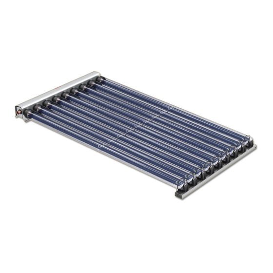
VIESMANN Installation instructions for heating engineers Vitosol 200 Type SD2 Direct flow vacuum tube collector VITOSOL 200 Dispose after installation. 5862 788 GB 5/2005... - Page 2 Safety instructions Please follow these safety instructions closely to prevent accidents and material losses. Safety instructions explained Regulations Danger Observe the following when working This symbol warns against the on this system & risk of injury. all legal instructions regarding the prevention of accidents, &...
-
Page 3: Table Of Contents
Index Preparing the installation Earthing and lightning protection of the solar heating system ....... Installation steps Horizontal rooftop installation..............& Component summary ................& Fitting the roof hooks or mounting brackets ..........& Fitting mounting rails................13 & Fitting the connecting chamber ..............17 Vertical rooftop installation................ -
Page 4: Earthing And Lightning Protection Of The Solar Heating System
Earthing and lightning protection of the solar heating system Install an electrical conductor on the The connection of the collector sys- pipework of the solar circuit in the tem to a new or existing lightning pro- lower part of the building in compli- tection system or the provision of ance with VDE or local regulations. -
Page 5: Horizontal Rooftop Installation
Horizontal rooftop installation Component summary... - Page 6 Horizontal rooftop installation (cont.) qR Hexagon nit Roof tile cover 1 Timber qT Mounting rail qZ Mounting rail with tube holder & 38 x 58 x 2430 mm qU Retaining plate & 30 x 100 x 2430 mm 2 Roof hooks qI Locking profile 3 Zinc-plated countersunk chip- qO Spacer...
-
Page 7: Fitting The Roof Hooks Or Mounting Brackets
Horizontal rooftop installation (cont.) Fitting the roof hooks or mounting brackets Overview — Installation with roof hooks D Mounting rail with tube holder Dimension x according to the width of E Mounting rail the tile head. Dimensions a to e see F Timber, 38 x 100 mm table on page 9. - Page 8 Horizontal rooftop installation (cont.) Overview — Installation with mounting brackets (e.g. on sheet steel roofs) A Spacer D Mounting rail with tube holder B Connecting chamber H Mounting rail C Mounting bracket...
- Page 9 Horizontal rooftop installation (cont.) Combination mm b mm c mm d mm e (tubes) — — — 1439 — — — 2149 1260 20/20 1439 1439 1465 2315 20/30 1439 2149 1820 2875 30/20 2149 1439 1260 1820 2875 30/30 2149 2149 1260...
- Page 10 Horizontal rooftop installation (cont.) For installations without roof hooks, mounting brackets are used in place of roof hooks. Centre the mounting rails, maintaining dimension f = 26 mm.
- Page 11 Horizontal rooftop installation (cont.) Fitting roof hooks for roof tile cover 1. Push up the roof tiles in accor- 3. Hook the roof hooks into the timber dance with the dimensions shown in accordance with the dimensions in the illustrations on page 7 shown in the illustrations on page 7 and 10.
- Page 12 Horizontal rooftop installation (cont.) Fitting roof hooks for slate cover 1. Mark the position of the roof hooks in accordance with the dimensions shown in the illustrations on page 7 and 10. 2. Remove slates from the roof hook area. 3.
-
Page 13: Fitting Mounting Rails
Horizontal rooftop installation (cont.) Fitting roof hooks for plain tile cover 1. Mark the position of the roof hooks in accordance with the dimensions shown in the illustrations on page 7 and 10. 2. Remove tiles from the roof hook area. - Page 14 Horizontal rooftop installation (cont.) 1. Secure the mounting rails to the roof hooks or mounting brackets; align vertically and horizontally. A Roof hooks or mounting brackets...
- Page 15 Horizontal rooftop installation (cont.) 2. Secure the retaining plates to the mounting rails. 3. Secure the mounting brackets to the mounting rails.
- Page 16 Horizontal rooftop installation (cont.) 4. Align the mounting rails with the tube holders and secure to the mounting bracket. Note Tube holders must be aligned later- ally to the opposite rail. 5. Screw the mounting bracket to the other side of the mounting rail. 6.
-
Page 17: Fitting The Connecting Chamber
Horizontal rooftop installation (cont.) Fitting the connecting chamber Turn T-slot bolts 90° for all installation steps. 1. Position the connecting chamber onto the mounting rails and click it into the retaining plates. 2. Align the connecting chambers. Note The tube holders on the mounting rails must be in line with those in the connecting chambers;... - Page 18 Horizontal rooftop installation (cont.) 3. Mark the fixing points at the back of the connecting chamber. Use centering groove as a tem- plate. 4. Drill 7 9 mm holes. 5. Tighten the connecting chamber. 6. Where several collectors are installed above each other, con- tinue with "Installing the connecting chamber"...
-
Page 19: Vertical Rooftop Installation
Vertical rooftop installation Component summary... - Page 20 Vertical rooftop installation (cont.) qE Washer Roof tile cover 1 Timber qR Hexagon nut qT Mounting rail & 38 x 58 x 2430 mm qZ Mounting rail with tube holder & 30 x 100 x 2430 mm 2 Roof hooks qU Retaining plate 3 Zinc-plated countersunk chip- wP Connecting chamber...
-
Page 21: Fitting Roof Hooks Or Mounting Brackets
Vertical rooftop installation (cont.) Fitting roof hooks or mounting brackets Overview — Installation with roof hooks E Roof hooks Dimension x according to the width of F Timber, 38 x 58 mm the tile head. (only for roof tiles) A Vacuum tube G Timber, 30 x 100 mm B Clamping bracket (only for roof tiles) - Page 22 Vertical rooftop installation (cont.) Overview — Installation with mounting brackets (e.g. on sheet steel roofs) A Vacuum tube E Mounting rail B Clamping bracket F Retaining plate C Mounting rail with tube holder G Connecting chamber D Mounting bracket...
- Page 23 Vertical rooftop installation (cont.) Secure the mounting brackets to the substructure in accordance with the dimensions given in the illustrations on page 22 and 24.
- Page 24 Vertical rooftop installation (cont.) For installations without roof hooks, mounting brackets are used in place of roof hooks. Centre the mounting rails, maintaining dimension f = 26 mm. Combination mm b mm c (tubes) — — — — — — —...
- Page 25 Vertical rooftop installation (cont.) Fitting roof hooks for roof tile cover 1. Push up the roof tiles in accor- 3. Hook the roof hooks into the timber dance with the dimensions shown in accordance with the dimensions in the illustration on page 21. shown in the illustration on page 24.
- Page 26 Vertical rooftop installation (cont.) Fitting roof hooks for slate cover 1. Mark the position of each roof hook in accordance with the dimensions shown in the illustration on page 24. 2. Remove slates from the roof hook area. 3. Secure the roof hooks to the roof surface.
-
Page 27: Fitting The Mounting Rails
Vertical rooftop installation (cont.) Fitting roof hooks for plain tile cover 1. Mark the position of each roof hook in accordance with the dimensions shown in the illustration on page 24. 2. Remove tiles from the roof hook area. 3. Hook the roof hooks onto the bat- tens and position and align on top of the tile below. - Page 28 Vertical rooftop installation (cont.) 1. Secure the mounting rails to the roof hooks or mounting brackets; align vertically and horizontally. A Roof hooks or mounting brackets 2. Secure the retaining plates to the mounting rails.
- Page 29 Vertical rooftop installation (cont.) Centre the mounting rails, maintaining dimension f = 26 mm. 3. Fit clamping brackets onto the mounting rails; do not yet tighten the bolts. 4. Click mounting rails with tube holders into the clamping brackets, align and fasten. Note Tube holders must be aligned later- ally to the opposite rail.
-
Page 30: Fitting The Connecting Chamber
Vertical rooftop installation (cont.) Fitting the connecting chamber Turn T-slot bolts 90° for all installation steps. 1. Position the connecting chamber 3. Tighten the mounting rails with the onto the mounting rails and click it clamping brackets. into the retaining plates. 4. -
Page 31: Installation On Flat Roofs
Installation on flat roofs Component summary... - Page 32 Installation on flat roofs (cont.) 1 Rawl plug S10 Connecting pipe (short) 2 Washer Connecting pipe (long) 3 Hexagon screw 8x70 mm Profile clip qQ Clamping bracket Locking ring fitting (elbow 90°), qW T-slot bolt 7 22 mm qE Washer Support sleeve qR Hexagon nut U-pipe...
-
Page 33: Fitting The Mounting Rails
Installation on flat roofs (cont.) Fitting the mounting rails Turn T-slot bolts 90 ° for all installation steps. Position the collector array as far south as possible; longitudinal tube axis aligned east-west. Centre the mounting rails, maintaining dimension d = 26 mm. A Foot A B Foot B... - Page 34 Installation on flat roofs (cont.) Combination mm b mm c (tubes) — — — — 1260 20/20 1465 2315 20/30 1820 2875 30/20 1260 1820 2875 30/30 1260 2175 3435 1. Position feet on a solid surface on protective mats. A Foot A B Foot B 2.
- Page 35 Installation on flat roofs (cont.) 4. Secure the retaining plates to the 6. Click the mounting rails with tube mounting rails. holders into the clamping brackets, align and tighten. 5. Fit the clamping brackets onto the Note mounting rails; do not yet tighten the bolts.
-
Page 36: Fitting The Connecting Chamber
Installation on flat roofs (cont.) Fitting the connecting chamber Turn T-slot bolts 90 ° for all installation steps. 1. Position the connecting chamber 3. Tighten the connecting chamber onto the mounting rails and click it with the clamping brackets. into the retaining plates. 4. -
Page 37: Installation On Walls
Installation on walls Component summary... -
Page 38: Fitting The Mounting Rails
Installation on walls (cont.) 1 Rawl plug S10 Connecting pipe (short) 2 Washer Connecting pipe (long) 3 Hexagon screw 8x70 mm Profile clip qP Mounting bracket Locking ring fitting (elbow 90°), qW T-slot bolt 7 22 mm qE Washer Support sleeve qR Hexagon nut U-pipe qT Mounting rail... - Page 39 Installation on walls (cont.) Centre the mounting rails, maintaining dimension d = 26 mm. Combination mm b mm c (tubes) — — — — 1260 20/20 1465 2315 20/30 1820 2875 30/20 1260 1820 2875 30/30 1260 2175 3435...
- Page 40 Installation on walls (cont.) 1. Fix the mounting brackets to the 2. Align the mounting rails and secure wall according to the dimensions to the mounting brackets. on page 39.
- Page 41 Installation on walls (cont.) 3. Secure the retaining plates to the 5. Align the mounting rails with the mounting rails. tube holders and secure to the mounting bracket. 4. Secure the mounting brackets to Note the mounting rails. Tube holders must be aligned later- ally to the opposite rail.
-
Page 42: Fitting The Connecting Chamber
Installation on walls (cont.) 6. Secure the mounting bracket to the other side of the mounting rail. 7. Secure the locking bracket at the bottom of the mounting rails with the tube holders. Fitting the connecting chamber Turn T-slot bolts 90 ° for all installation steps. - Page 43 Installation on walls (cont.) 1. Position the connecting chamber onto the mounting rails and click into the retaining plate. 2. Align the connecting chambers. Note The tube holders on the mounting rails must be in line with those in the connecting chambers; where necessary, align with a piece of string.
- Page 44 Installation on walls (cont.) 3. Mark the fixing points at the back of the connecting chamber. Use the centering groove as a tem- plate. 4. Drill 7 9 mm holes. 5. Secure the connecting chamber. 6. Where several collectors are installed above each other, con- tinue with "Installing the connecting chamber"...
-
Page 45: Water Connections
Water connections Installing the connecting chamber Interconnecting pipes should not 2. Push the next connecting cham- cause any damage. bers carefully onto the first and Lubricate all plug-in connections (O- insert the interconnecting pipes. ring seals) on the collectors only with the special lubricating grease 3. -
Page 46: Fitting The Vacuum Tubes
Water connections (cont.) Fitting the vacuum tubes Danger The vacuum tubes can become hot or break if insufficient care is taken.This can lead to severe burns or injury. Wear gloves and safety gog- gles. A Template B Locking spring 1. Remove protective caps from the tubes. - Page 47 Water connections (cont.) 2. Push the tubes into the tube 3. For south-facing roofs, adjust the holders until they click and push angle of inclination of the absorber them into the header as far as pos- with the enclosed template. sible.
-
Page 48: Installing The Connection Set And Collector Temperature Sensor
Water connections (cont.) Installing the connection set and collector temperature sen- & Observe the following when fitting the Push the pipe into the locking ring locking ring fitting: fitting as far as it will go. & & All pipes must be right-angled and Initially turn the union nut by hand, must be deburred. - Page 49 Water connections (cont.) 1. Insert the connection pipes as far 7. Insert the U-pipe as far as possi- as possible, then secure them ble, then secure it with profile with hose clips. clips. 2. Fit the elbow onto the return con- 8.
- Page 50 Water connections (cont.) Connection to the left RL Return (short connection pipe) VL Flow (long connection pipe) 1. Insert the connection pipes as far 2. Fit the elbow onto the return con- as possible, then secure them nector. with profile clips.
-
Page 51: Installation
Water connections (cont.) 3. Fit the tee onto the flow connec- 8. Insert the support sleeves into the tor. pipework of the solar circuit. Make the connection between the 4. Insert the sensor well into the tee, collector array and pipework of holding the tee tightly. - Page 52 Installation (cont.) A Collector H Manual solar fill pump B Solar-Divicon K Fill valve (F, G, H) C Collecting tank L Drain D Expansion vessel M Air separator E Pre-cooling vessel (if required) N DHW cylinder F Shut-off valve O Solar control unit G Fill set P Air vent valve...
-
Page 53: Commissioning And Adjustment
Installation (cont.) 1. Route pipes so that they can be 3. The expansion vessel must be completely vented. Install at least approved to DIN 4807 and must be one air vent valve with shut-off arranged with a heat insulating facility at the highest point of the loop. - Page 56 Viessmann Limited Hortonwood 30, Telford, TF1 7YP, GB Telephone: +44 1952 675000 Fax: +44 1952 675040 www.viessmann.com...