Viessmann Vitosol-F Installation Instructions Manual
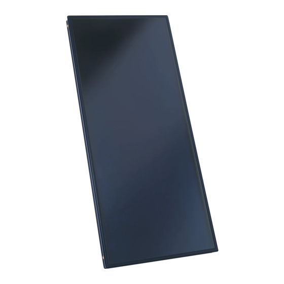
Flat-plate collector for pitched roofs
Hide thumbs
Also See for Vitosol-F:
- Installation instructions manual (80 pages) ,
- Installation instructions for contractors (24 pages) ,
- Service instructions manual (24 pages)
Table of Contents
Advertisement
Quick Links
Advertisement
Table of Contents

Related Manuals for Viessmann Vitosol-F


Summary of Contents for Viessmann Vitosol-F
- Page 1 VIESMANN Installation instructions for contractors Vitosol-F/-FM Type SV and SH Flat-plate collector for pitched roofs Above roof installation with rafter anchors or mounting brackets VITOSOL-F/-FM Dispose after installation. 5698324 GB/en 9/2017...
- Page 2 Safety instructions Please follow these safety instructions closely to prevent accidents and material losses. Safety instructions explained Please note Note This symbol warns against the risk of material Details identified by the word "Note" contain additional losses and environmental pollution. information.
-
Page 3: Table Of Contents
Index Information Disposal of packaging ................Symbols ....................Intended use ..................Preparing for installation Observe prior to installation ..............Type SV (vertical collectors) ............... ■ Type SH (horizontal collectors) ............■ Installation sequence Installation with rafter anchors ............... 11 Components ..................11 ■... -
Page 4: Information Disposal Of Packaging
Disposal of packaging Disposal of packaging DE: Use the disposal system organised by Viessmann. Please dispose of packaging waste in line with statu- AT: Use the ARA statutory disposal system (Altstoff tory regulations. Recycling Austria AG, licence number 5766). CH: Packaging waste is disposed of by the HVAC contractor. -
Page 5: Intended Use
Intended use The appliance is only intended to be installed and Any usage beyond this must be approved by the man- operated in sealed unvented systems that comply with ufacturer for the individual case. EN 12828 / DIN 1988, or solar thermal systems that comply with EN 12977, with due attention paid to the Incorrect usage or operation of the appliance (e.g. -
Page 6: Preparing For Installation Observe Prior To Installation
Observe prior to installation For each number of collectors, there is a specific allo- Example: cated number of rafter anchors or mounting brackets ■ 2 collectors type SV (for use on sheet steel roofs). Rafter spacing a 600 mm ■ The spacing between rafters and the potential snow ■... - Page 7 Observe prior to installation (cont.) 4 collectors Rafter spacing in Snow load in kN/m 0.75 0.75 1.25 1.25 2.55 2.55 4.80 ≤ > ≤ > ≤ > ≤ 1, 4, 5, 8 1, 3, 4, 5, 6, 8 ≤ 1, 3, 4, 6 1, 3, 4, 5, 7 ≤...
-
Page 8: Type Sh (Horizontal Collectors)
Observe prior to installation (cont.) Type SH (horizontal collectors) With 3 collectors or more, the distribution of the rafter anchors on the upper and lower mounting rail may vary. 1 collector Rafter spacing in Snow load in kN/m 1.25 1.25/ 2.55 ≤... - Page 9 Observe prior to installation (cont.) 5 collectors Rafter spacing in Mounting rail Snow load in kN/m , to 1.25 1.25/ 2.55 ≤ > ≤ 1, 5, 9, 13, 17, 21 ≤ bottom 1, 4, 5, 8, 11.14, 15, 18 ≤ 1, 4, 8, 11, 15, 18 1, 4, 8, 11, 15, 18 1, 4, 7, 10, 13, 16...
- Page 10 Observe prior to installation (cont.) 10 collectors Rafter spacing in Mounting rail Snow load in kN/m 1.25 1.25/ 2.55 ≤ > ≤ 1, 5, 9, 13, 17, 21, 25, 29, 33, 37, 41 ≤ bottom 1, 4, 8, 11, 15, 18, 21, 25, 28, 32, 1, 4, 5, 8, 11, 14, 15, 18, 21, 22, 25, ≤...
-
Page 11: Installation Sequence Installation With Rafter Anchors
Installation with rafter anchors Components Ø 8.4 M8x25 Fig. 2 Plastic replacement tile, if the existing tiles are not to be cut. Use only on roofs with a pitch of at least 12°. Fig. 3 Supporting rails: For type SV with snow loads of 4.80 kN/m... -
Page 12: Installation
Installation with rafter anchors (cont.) Installation Fig. 4 Fig. 5 Type a in mm 1650 1900 – –... - Page 13 Installation with rafter anchors (cont.) Only for type SV with snow loads of 4.80 kN/m Fig. 6 Fit 3 rafter anchors one above the other; average out dimension b. Fig. 7...
- Page 14 Installation with rafter anchors (cont.) Installation with trimmed tiles Fig. 8 Fig. 9 Continue with step 16 on page 16.
- Page 15 Installation with rafter anchors (cont.) Installation with plastic replacement tiles Fig. 10 Fig. 11...
- Page 16 Installation with rafter anchors (cont.) Fig. 12 90 ° Fig. 13 Number of collectors c in mm Type SV Type SH Continue with "Installing the collectors" (see page 20).
-
Page 17: Installation With Mounting Brackets
Installation with rafter anchors (cont.) Note for type SV For snow loads of 4.80 kN/m supporting rails must be fitted; see diagram below. Ø 8.5 90 ° Fig. 14 Continue with "Installing the collectors" (see page 20). Installation with mounting brackets E.g. -
Page 18: Installation
Installation with mounting brackets (cont.) Fig. 16 Supporting rails: For type SV with snow loads of 4.80 kN/m Installation On-site fixings are required for securing the mount- The installation of the mounting bracket is shown using ing brackets (see diagram below). standing seam profiles as an example. - Page 19 Installation with mounting brackets (cont.) Note for type SV For snow loads of 4.80 kN/m , fit 3 mounting brackets one above the other; see diagram on page 13. 90° Fig. 18 Number of collectors c in mm Type SV Type SH...
-
Page 20: Installing The Collectors
Installation with mounting brackets (cont.) Note for type SV For snow loads of 4.80 kN/m supporting rails must be fitted; see diagram below. Ø 8.5 90 ° Fig. 19 Installing the collectors Fig. 20 Installation information Please note ■ The first and last collector must be positioned with The connection pipes must be free of any signs the type plate facing outwards (observe label). - Page 21 Installing the collectors (cont.) Fig. 21 Number of collectors x in mm Type SV Type SH Fig. 22...
-
Page 22: Connecting The Collectors
Connecting the collectors Fig. 23 Fig. 24 Installation information Lubricate O-ring seals only with the special valve ■ grease provided. ■ Initially tighten the union nut by hand, then tighten with an open-ended spanner by a further turn. ¾ ■ Never use annealed copper pipes with locking ring fittings. -
Page 23: Covering The Collector Array
Soft solder could be weakened, particularly near the collectors, due to the high temperatures that occur there. Metal seal connections, locking ring fittings or Viessmann plug-in connections with double O-rings are the most suitable. If other seals such as flat gaskets are used, ade- quate glycol, pressure and temperature stability must be guaranteed by the manufacturer. -
Page 24: Commissioning
Cylinder temperature sensor Drain valve Collector temperature sensor Flow indicator Solar control unit Commissioning "Vitosol-F/-FM" service instructions Viessmann Werke GmbH & Co. KG Viessmann Limited D-35107 Allendorf Hortonwood 30, Telford Telephone: +49 6452 70-0 Shropshire, TF1 7YP, GB Fax: +49 6452 70-2780 Telephone: +44 1952 675000 www.viessmann.com...