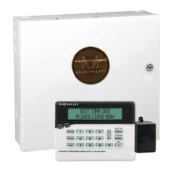
NAPCO Gemini GEM-P3200 Programming Instructions Manual
Control panel/communicator
Hide thumbs
Also See for Gemini GEM-P3200:
- Programming instructions manual (68 pages) ,
- Installation instructions manual (68 pages) ,
- Addendum (2 pages)
Table of Contents
Advertisement
Quick Links
HARDWIRE
CONTROL PANEL/COMMUNICATOR
"Classic" GEM-RP2ASe2, GEM-RP3DGTL, and GEM-RP4RFC/GEM-RP4C Keypads and
the "K Series" GEM-K2AS, GEM-K3DGTL, and GEM-K4RF/GEM-K4 Keypads
"K Series" GEM-K2AS
Quick Start (for GEM-K2ASe2):
1.
Refer to the wiring diagram, connect Siren, Aux. Power, PGM
Output, Remote Bus, Earth Ground, Zone and Telephone
Wiring. NOTE: See Installation Instructions (WI817).
2.
Connect AC power first and then the battery.
3.
Configure the keypad (see page 65).
4.
Access the Easy Menu Driven (Dealer Program) Mode:
Press:
EEEEEE
Master Security Code
(on microshield)
Press NO until "
TURNON PROG Y/N
Press NEXT/YES to enter Dealer Program Mode. See page 5
© NAPCO 2006
Publicly traded on NASDAQ
R
G E M - P 3 2 0 0
Programming the GEM-P3200 Control Panel with the
"K Series" GEM-K4RF/GEM-K4
R
" appears on the keypad display.
Symbol: NSSC
PROGRAMMING
INSTRUCTIONS
WIRELESS
32
32
Quick Start (for GEM-K3DGTL):
1.
Refer to the wiring diagram, connect Siren, Aux. Power, PGM
Output, Remote Bus, Earth Ground, Zone and Telephone
Wiring. NOTE: See Installation Instructions (WI817).
2.
Connect AC power first and then the battery.
3.
Configure the keypad (see page 65).
4.
Access the Easy Menu Driven (Dealer Program) Mode:
Press:
EEEEEE
Master Security Code
(on microshield)
Press NO until "17" appears on the keypad display.
Press NEXT/YES to enter Dealer Program Mode. See page 5.
"K Series" GEM-K3DGTL
R
WI1184B 2/06
Advertisement
Table of Contents

Related Manuals for NAPCO Gemini GEM-P3200


Summary of Contents for NAPCO Gemini GEM-P3200
- Page 1 Press NO until “17” appears on the keypad display. TURNON PROG Y/N Press NEXT/YES to enter Dealer Program Mode. See page 5 Press NEXT/YES to enter Dealer Program Mode. See page 5. © NAPCO 2006 WI1184B 2/06 Publicly traded on NASDAQ Symbol: NSSC...
-
Page 2: Important Note
• Addition to the Easy Program Menu instructions, "Enter Proximity Card Users". Existing addresses were changed and new addresses were added to accommodate the NAPCO NetLink™ NL-Mod device, as follows: • (Address 0526, 0551 & 0576) For each telephone number desired, enable "Report to TCP/IP Receiver or AES" for Telco 1, Telco 2 and Telco 3. -
Page 3: Table Of Contents
CS ZONE REPORTING CODES (ADDRESS 0910-0957) ....35 ADDRESS NUMBER LOCATION INDEX ..........71 CS USER REPORTING CODES (ADDRESS 1030-1048) ....36 GEM-P3200 WIRING DIAGRAM ..............76 CS USER REPORTING CODES (ADDRESS 1056-1074) ....37 Refer to accompanying GEM-P3200 Installation Instructions (WI817) for installation information. NAPCO Security Systems GEM-P3200 Programming Instructions... -
Page 4: System Programming Options
Similarly, a high-speed local download may be made in the field using a notebook or laptop computer. Connect JP2 on the control panel to a Napco PCI-MINI computer interface using the 6-conductor cable supplied. (Refer to PCI-MINI Installation Instructions WI767). -
Page 5: Easy Menu Driven Program Mode
Should it be necessary to create a new custom default program, (a) from the Dealer Program Mode, press the button to enter the Direct Address Program Mode; (b) access Location 4091 (Clear Program); (c) press the button and start over. NAPCO Security Systems GEM-P3200 Programming Instructions... -
Page 6: Gem-Rp2Ase2/Gem-K2As Keypad Easy Program Menu
• Press the NEXT/YES button to proceed. (Direct Entry) • All Interior zones will also be automatically programmed as “Exit/Entry Follower” and as "Power Up Delay" zones. NAPCO Security Systems GEM-P3200 Programming Instructions... - Page 7 NEXT/YES button to proceed. • Auto Bypass Re-entry Zones allow the system to be armed with the zone faulted but come back into the system (armed) (Direct Entry) when the zone is subsequently closed. NAPCO Security Systems GEM-P3200 Programming Instructions...
- Page 8 • Press to save and press the NEXT/YES button to proceed. NOTE: Central Station Receiver 2 and 3 Telephone Numbers must be en- (Direct Entry) tered in Direct Address Programming. See CS Receiver Options. NAPCO Security Systems GEM-P3200 Programming Instructions...
- Page 9 Sescoa, Vertex, DCI, Franklin Radionics Modem 2 entered Direct Address Fast Radionics Fast Programming. See CS Receiver Options. Ademco Point ID Silent Knight Fast Ademco Express Radionics, DCI, Franklin Slow Pager Universal High Speed Radionics BFSK NAPCO Security Systems GEM-P3200 Programming Instructions...
- Page 10 LEVEL 3 AMBUSH *Note: These entries are only Note: “Y” indicates option is enabled. Note: “Y” indicates option is enabled. Note: “Y” indicates option is enabled. available when address 3905 bit 7 is enabled. NAPCO Security Systems GEM-P3200 Programming Instructions...
- Page 11 CHANGING OR CANCELING A CODE: To change any code, merely program over the existing code as described above and press to save. Similarly, to cancel a code, blank out each number of the code and press to save to save. NAPCO Security Systems GEM-P3200 Programming Instructions...
- Page 12 (UP TO 6 DIGITS) ACM AREA DATA ENTRIES blank (•) NONE DATA ACCESS CODE ENTRIES LEVEL TYPE blank (•) NONE NONE NONE ARM/DISARM ARM/DISARM ARM/DISARM ARM ONLY ARM ONLY ARM ONLY Note: “Y” indicates option is enabled. NAPCO Security Systems GEM-P3200 Programming Instructions...
- Page 13 NOTE: When programming the ID Code number, “0” through ”9” = 0 through 9; A = G0; B = G1; C = G2; D = G3; E = G4 and “F” = G5. (Direct Entry) NAPCO Security Systems GEM-P3200 Programming Instructions...
- Page 14 This erases all programmed data (Dealer Program, Zone Description Data and Schedules). Access 4 0 9 3 X X address 4093 and press . Data entry is not allowed. NOTE: Some features (schedules) can only be programmed again with the Downloading Software. NAPCO Security Systems GEM-P3200 Programming Instructions...
-
Page 15: Gem-Rp3Dgtl/Gem-K3Dgtl And Gem-Rp4Rfc/Gem-K4Rf Keypad Easy Program Menu
NEXT/YES button to proceed. NOTE: Entry Delay Time of 30 seconds and Exit Delay Time of 60 seconds will automatically be pro- grammed. INTERIOR BYPASS FIRE/TBL SYS TBL CHIME (Direct Entry) NAPCO Security Systems GEM-P3200 Programming Instructions... - Page 16 Press the NEXT/YES button to proceed. NOTE: A Sensor Watch Time of 24 hours will automatically be programmed. INTERIOR BYPASS FIRE/TBL SYS TBL CHIME (Direct Entry) NAPCO Security Systems GEM-P3200 Programming Instructions...
- Page 17 Press the NEXT/YES button to proceed. NOTE: Area 2 keypads must have zones in Area 2, otherwise the keypad will indicate "Out of System". INTERIOR BYPASS FIRE/TBL SYS TBL CHIME (Direct Entry) NAPCO Security Systems GEM-P3200 Programming Instructions...
- Page 18 Sescoa, Vertex, DCI, Franklin Radionics Modem 2 entered Direct Address Fast Programming. See CS Receiver Options. Radionics Fast Ademco Point ID Silent Knight Fast Ademco Express Radionics, DCI, Franklin Slow Pager Universal High Speed Radionics BFSK NAPCO Security Systems GEM-P3200 Programming Instructions...
- Page 19 ARM ONLY LEVEL 3 ARM ONLY NONE SERVICE LEVEL 1 SERVICE LEVEL 2 SERVICE LEVEL 3 SERVICE Note: “Y” indicates option is enabled. Note: “Y” indicates option is enabled. Note: “Y” indicates option is enabled. NAPCO Security Systems GEM-P3200 Programming Instructions...
- Page 20 CHANGING OR CANCELING A CODE: To change any code, merely program over the existing code as described above and press to save. Similarly, to cancel a code, blank out each number of the code and press to save to save. NAPCO Security Systems GEM-P3200 Programming Instructions...
- Page 21 (UP TO 6 DIGITS) ACM AREA DATA ENTRIES blank (•) NONE DATA ACCESS CODE ENTRIES LEVEL TYPE blank (•) NONE NONE NONE ARM/DISARM ARM/DISARM ARM/DISARM ARM ONLY ARM ONLY ARM ONLY Note: “Y” indicates option is enabled. NAPCO Security Systems GEM-P3200 Programming Instructions...
- Page 22 NEXT/YES button to proceed when all keyfobs have been entered. NOTE: When programming the ID Code number, “0” through ”9” = 0 through 9; A = G0; B = G1; C = G2; D = G3; E = G4 and “F” = G5. NAPCO Security Systems GEM-P3200 Programming Instructions...
- Page 23 Interior Bypass ("Classic" RP Series Keypads only) ZONE DESCRIPTIONS: GEM-RP2ASe2/GEM-K2AS cannot be used to enter the date or time or Zone Descriptions. To enter this information, you must use the GEM-RP1CAe2 or GEM-K1CA Keypad (See WI818) or the Napco Quickloader Software. Dealer Code •...
-
Page 24: Direct Address Program Mode
(The panel and keypad version appears briefly on the keypad display). 4. Press C to exit Easy Menu Driven Program Mode & enter Direct Address Program Mode. (For keypad display examples when in Program Mode, see next page). NAPCO Security Systems GEM-P3200 Programming Instructions... -
Page 25: Keypad Address Program Mode Display
C O M P U T E R I ZE D S E C U R I T Y S Y S T E M To exit, press C. NOTE: Press 0 button to clear character at cursor. Select NEXT/PRIOR Address. Press to jump to next programming block. * Press through for 10-15, respectively. NAPCO Security Systems GEM-P3200 Programming Instructions... - Page 26 (•) in the right digit. 6. Press to save. Address 0506 is now programmed with “E •”. 7. Enter another 4-digit address to continue programming or press to exit and resume normal keypad operation. NAPCO Security Systems GEM-P3200 Programming Instructions...
-
Page 27: Conventions Used In This Manual
• program. It is recommended that the panel be uploaded to NAPCO's PCD Windows software following any keypad programming and that the PCD Windows error-check feature be utilized to reduce the possibility of programming omissions or conflicts. Note: Most of the addresses shown comprise two data entry locations, left and right digits. -
Page 28: Programming Options & Worksheets
Left Digit 16 20 4 Remainder Right Digit A. Choose a desired delay/timeout , ex: 20. Note: For Sensor Watch only divide it by 10, ex: 20/10 = 2. B. Divide it by 16 NAPCO Security Systems GEM-P3200 Programming Instructions... -
Page 29: System Delays & Timeouts (Address 2400, 2401, 2403-2405, 4082 & 4083)
DEALER SECURITY CODE: Enter up to 6 digits to be used by the dealer to enter programming. 1. Enter in both left and right digits of address locations. 2. Valid entries are: 0-9. Note: If left blank, the Master Security Code must then be used to enter programming. NAPCO Security Systems GEM-P3200 Programming Instructions... -
Page 30: Cs Receiver Format Options
1. Select the desired option by circling the data values for each digit * If both are selected, 1400Hz has priority over 2300Hz. ** For NAPCO NetLink™ installations only: For each (left and right). telephone number desired, enable to allow the panel to report alarms via the NL-MOD accessory. -
Page 31: Cs Receiver Telephone Numbers (Address 0527-0546, 0552-0571, 0577-0596)
1. Enter in right digit only (left digit is not used). 2. Valid entries are: 0-9. 2. Valid entries are: 1 or 2. Note: Download Security Code must match the code entered in the PCD3000 Software. NAPCO Security Systems GEM-P3200 Programming Instructions... -
Page 32: Cs Subscriber Id Numbers (Address 0650-0787)
CS TELCO 2 SUBSCRIBER EVENT ID NUMBERS (BACKUP REPORTING) AREA 1 AREA 2 SYSTEM ADDRESS 0756-0759 ADDRESS 0752-0755 ADDRESS 0784-0787 (RIGHT DIGITS 1-4) 0756 0757 0758 0759 0784 0785 0786 0787 0752 0753 0754 0755 NAPCO Security Systems GEM-P3200 Programming Instructions... -
Page 33: Cs Subscriber Id Numbers (Address 0790-0857)
0862 Opening after Alarm blank (•) 0867 shows option not available. Fail to Open 0868 Fail to Close 0869 [Default = blank (•) blank (•) from address 0859-0883] Telemetry Trouble 0882 Telemetry Fail 0883 NAPCO Security Systems GEM-P3200 Programming Instructions... -
Page 34: Cs Reporting Codes (Address 0870-0904)
Dialing. Leave blank (•) to select Rotary 2. Add the data values (ex: 15=1+2+4+8) from the selected options. Dialing. 3. Enter in address location (left and right digits). NOTE: Dark shaded data value box shows option not available. NAPCO Security Systems GEM-P3200 Programming Instructions... -
Page 35: Cs Zone Reporting Codes (Address 0910-0957)
MODEM CODES determine the zone types reported for the following formats: SIA and ADEMCO Point Hold up Gas Alarm 1. Select the desired Modem Code for each zone from the table shown. Heat Alarm Auxiliary Alarm 24 Hour Auxiliary NAPCO Security Systems GEM-P3200 Programming Instructions... -
Page 36: Cs User Reporting Codes (Address 1030-1048)
User User LEFT RIGHT LEFT RIGHT Telco 1 NOTE: These opening events will report as the user number shown. Also, Keyfobs 01-08 (see Easy Menu Program Driven Mode) will report as Users 25-32, respectively. NAPCO Security Systems GEM-P3200 Programming Instructions... -
Page 37: Cs User Reporting Codes (Address 1056-1074)
User User LEFT RIGHT LEFT RIGHT Telco 3 NOTE: These opening events will report as the user number shown. Also, Keyfobs 01-08 (see Easy Menu Program Driven Mode) will report as Users 25-32, respectively. NAPCO Security Systems GEM-P3200 Programming Instructions... -
Page 38: Global System Trouble Reporting Options (Address 1082-1116)
(left and right). 2. Add the data values (ex: 15=1+2+4+8) from the selected options. 3. Enter in address location (left and right digits). NOTE: Dark shaded data value box shows option not available. NAPCO Security Systems GEM-P3200 Programming Instructions... -
Page 39: Area System Trouble Reporting Options (Address 1120-1137)
(left and right). 2. Add the data values (ex: 15=1+2+4+8) from the selected options. 3. Enter in address location (left and right digits). NOTE: Dark shaded data value box shows option not available. NAPCO Security Systems GEM-P3200 Programming Instructions... -
Page 40: Zone Options / Zones 1-16 (Address 1200-1386)
Disable Auto-Reset on non-fire zones for SIA CP-01 installations. In UL installations, all Fire Zones must also be programmed for "PulseBurg Output Cadence" (Address 2422, press 1 (bit zero)). See Zone Options on Page 43. NAPCO Security Systems GEM-P3200 Programming Instructions... -
Page 41: Zone Options / Zones 17-32 (Address 1402-1586)
Disable Auto-Reset on non-fire zones for SIA CP-01 installations. In UL installations, all Fire Zones must also be programmed for "PulseBurg Output Cadence" (Address 2422, press 1 (bit zero)). See Zone Options on Page 43. NAPCO Security Systems GEM-P3200 Programming Instructions... -
Page 42: Zone Options / Zones 33-48 (Address 1602-1786)
Disable Auto-Reset on non-fire zones for SIA CP-01 installations. In UL installations, all Fire Zones must also be programmed for "PulseBurg Output Cadence" (Address 2422, press 1 (bit zero)). See Zone Options on Page 43. NAPCO Security Systems GEM-P3200 Programming Instructions... -
Page 43: Zone Options / Zones 1-48 (Address 1200-1786)
Fire, Pulse Alarm Output and Fire Verification is enabled for the zone numbers entered in “FIRE ZONES” 2-Wire Smoke Detector is enabled for zone numbers entered in “2 WIRE FIRE ZONES” Note: See “Number of Zones & Keypads per Area” in Easy Menu Driven program Mode. NAPCO Security Systems GEM-P3200 Programming Instructions... -
Page 44: System Options (Address 2415-2419)
2. Add the data values (ex: 15=1+2+4+8) from the selected options. 3. Enter in address location (left and right digits). NOTE: Dark shaded data value box shows option not available. Do not enable on systems with "K Series" keypads. NAPCO Security Systems GEM-P3200 Programming Instructions... -
Page 45: System Options (Address 2420-2422, 3874)
(left and right). 2. Add the data values (ex: 15=1+2+4+8) from the selected options. 3. Enter in address location (left and right digits). NOTE: Dark shaded data value box shows option not available. NAPCO Security Systems GEM-P3200 Programming Instructions... -
Page 46: Alarm/Trouble Reporting Codes (Address 3879-3881)
R i g h t d i g i t RESERVED RESERVED (not used). Enter blank (•) RESERVED data in left digit only. Skip Automatic [Default = blank (•) blank (•)] Dial Tone Detect NAPCO Security Systems GEM-P3200 Programming Instructions... -
Page 47: Keypad Options (Address 2425-2446)
(left and right). 2. Add the data values (ex: 15=1+2+4+8) from the selected options. 3. Enter in address location (left and right digits). NOTE: Dark shaded data value box shows option not available. NAPCO Security Systems GEM-P3200 Programming Instructions... -
Page 48: Keypad Options (Address 2425-2446)
Default ACM GLOBAL FLAGS: Enable Two-Swipe Arming Select the desired option entering the option number Enable NAPCO Proprietary Access Format (1-8) for each digit. Enable Facility Code Enter corresponding option number in address loca- Enable Access Logging into Burg Log tion. -
Page 49: Acm Door Area Options (Address 2784-2787)
ACM 1 – Door 1 – 4072 ACM 1 – Door 2 – 4073 ACM 2 – Door 1 – 4074 ACM 2 – Door 2 – 4075 [Default = blank (•) blank (•) from address 4072-4075] NAPCO Security Systems GEM-P3200 Programming Instructions... -
Page 50: Keypad Home Area / Acm Door #1 Area (Hex) (Address 2425-2431)
2426 Press to save. 2427 2428 2429 2430 2431 NOTE: *[Default = blank (•) (1) for address 2425] First ACM/Keypad device must be a "keypad". [Default = blank (•) blank (•) from address 2426-2431] NAPCO Security Systems GEM-P3200 Programming Instructions... -
Page 51: System Options (Address 2423)
EMER GEN CY FREE AC CESS (AD DRESS 40 8 0) ENABLE ACM OPTION: Select the Emergency Free Access ADDRESS 4080 Zone Number (1-255) and enter corre- Emergency Free Access sponding address location at right. Zone Number Press to save. [Default = 000] NAPCO Security Systems GEM-P3200 Programming Instructions... -
Page 52: User Area Options (Address 2455-2502)
4 2 1 ADDRESS LOCATION NOTE: No circle = feature 4 2 1 ADDR disabled. blank (•) 2500 4 2 1 ZN04 ZN03 ZN02 ZN01 4 2 1 4 2 1 Draw Circle 4 2 1 NAPCO Security Systems GEM-P3200 Programming Instructions... -
Page 53: Ezm Group Options (Address 2600-2621)
2. Enable desired options for each area by drawing a circle around its corresponding binary data value. NOTE: No circle = feature disabled. 3. Enter data in corresponding left and right digit address locations above. NAPCO Security Systems GEM-P3200 Programming Instructions... -
Page 54: Area Arming Options (Address 2650-2651)
1. Select the desired option by circling the data values for each digit (left and right). 2. Add the data values (ex: 15=1+2+4+8) from the selected options. 3. Enter in address location (left and right digits). NAPCO Security Systems GEM-P3200 Programming Instructions... -
Page 55: Area Output Control Options (Address 2700-2733)
AREA OUTPUT TURNS OFF UPON DISARM: Select options for any of the 5 Outputs per area when disarming a particular area. 1. Select the desired option by circling the data values for left and right digits. 2. Add the data values (ex: 15=1+2+4+8) from the selected options. 3. Enter in right digit address location. NAPCO Security Systems GEM-P3200 Programming Instructions... -
Page 56: Rf Receivers & Supervisory Timer Options
Smoke Detector 3766 3774 Type 7 Smoke Detector Type F Napco Glass Break 3767 3775 [Default = blank (•) 8 from address 3760-3767 (80 minutes)] [Default = blank (•) 8 from address 3768-3775 (80 minutes)] RF SUPERVISORY TIMERS RF SUPERVISORY TIMERS... -
Page 57: External Relay Control / Relays
(RELAY/entry 23) (RELAY/entry 24) ADDRESS 3799 & 2884-2887 ADDRESS 3800 & 2888-2891 ADDRESS 3801 & 2892-2895 3799 2884 2885 2886 2887 3800 2888 2889 2890 2891 3801 2892 2893 2894 2895 (•) (•) (•) NAPCO Security Systems GEM-P3200 Programming Instructions... - Page 58 5A. Select Alarm Type and Timeout Type from Table 5A (see page 61); enter in corresponding address location (left digit). NOTE: Select Timeout from Step 3. 5B. Select Activation from from Table 5B (see page 61); enter in corresponding address location (right digit). NAPCO Security Systems GEM-P3200 Programming Instructions...
- Page 59 16 20 4 Remainder Right Digit For a desired relay not listed: 3 Quotient Left Digit A. Choose a desired relay, ex: 60 Continued B. Divide it by 16 16 60 C Remainder Right Digit NAPCO Security Systems GEM-P3200 Programming Instructions...
- Page 60 NOTE: Keypad Tamper must be enabled in Zone 39 UL installations using jumper option Zone 40 on keypad. blank (•) Zone 41 Zone 42 Zone 43 Zone 44 Zone 45 Zone 46 Zone 47 Zone 48 Continued NAPCO Security Systems GEM-P3200 Programming Instructions...
-
Page 61: Number Of Relay Board Modules (Address 3777)
1. Select the number of relay modules from the table blank (•) None [Default = blank (•) blank (•)] shown. 2. Enter in corresponding right digit address location shown (left digit is not used). NAPCO Security Systems GEM-P3200 Programming Instructions... -
Page 62: System Reset Options (Address 4091-4093)
GEM-RP2ASe2 Keypad 4093XX Access address 4093, then press the button. Data entry is not allowed. NOTE: Some features (schedules, language configuration) can only be re-programmed with the Downloading Software. NAPCO Security Systems GEM-P3200 Programming Instructions... -
Page 63: User Program Mode
Until “TURNON PROG Y/N” (GEM-RP2ASe2/GEM-K2AS) or “17” (GEM-RP3DGTL/GEM-K3DGTL or GEM-RP4RFC/ GEM-K4RF) appears on the LCD screen. 3. Press P To Enter User Program Mode. 4. Press C To Exit User Program Mode when finished. NAPCO Security Systems GEM-P3200 Programming Instructions... -
Page 64: User Codes
User Number each code. G 0 button to clear character at cursor. NOTE: Press CHIME To continue press P or Q button. User Code (Direct Entry) Programming User Codes with GEM-K4RF Keypad NAPCO Security Systems GEM-P3200 Programming Instructions... -
Page 65: Keypad Configuration Mode
Cut Jumper A to disable touch pad backlighting to conserve 11mA standby current. LCD BACKLIGHT Cut Jumper B to disable LCD backlighting. DISABLE SOUNDER Cut Jumper C to disable the sounder. (Do not disable in UL applications). NAPCO Security Systems GEM-P3200 Programming Instructions... -
Page 66: Alphabetical Index
AUTO BYPASS RE-ENTRY ZONES, 7, 17 CONFIGURING THE KEYPADS, 65 AUTO DISARM REARM DELAY ADDRESS 4083, 29 CONVENTIONS USED IN THIS MANUAL, 27 AUTO DOWNLOAD ID NO. ADDRESS 1023, 31 CS AREA & SYSTEM REPORTING OPTIONS (ADDRESS NAPCO Security Systems GEM-P3200 Programming Instructions... - Page 67 PC PRESET CALLBACK NUMBERS, 9 2419, 44 EMERGENCY FREE ACCESS (ADDRESS 4080), 51 DISABLE AREA ENTRY RELAYS ADDRESS 2422, 45 ENABLE ACCESS LOGGING INTO BURG LOG ADDRESS DISABLE AUTO-RESET ON DAY ZONE ADDRESS 2419, 44 2780, 48 NAPCO Security Systems GEM-P3200 Programming Instructions...
- Page 68 FIRE OUTPUT TIMEOUT ADDRESS 2405, 29 ENABLE MANAGER’S MODE OUTSIDE OVERVIEW ADDRESS 2418, 44 FIRE ZONES IN AREA 1, 6, 15 ENABLE NAPCO PROPRIETARY ACCESS FORMAT FORCED ENTRY ZONE, 48 ADDRESS 2780, 48 FUNCTION MODE ENABLE NO EOLR ZONES, 8, 17...
- Page 69 SINGLE DIGIT ONLY, 30 NUMBER OF KEYPADS IN AREA 2, 8, 17 SKIP AUTOMATIC DIAL TONE DETECT ADDRESS 4084, 46 NUMBER OF RELAY BOARD MODULES (ADDRESS 3777), SOUNDER OPENING REPORT ONLY AFTER ALARM REPORT DISABLE, 65 NAPCO Security Systems GEM-P3200 Programming Instructions...
- Page 70 TOTAL NUMBER OF ZONES IN AREA 2, 6, 15 TOUCHPAD BACK LIGHT, 65 TOUCH-TONE DIALING ONLY, 34 TOUCH-TONE DIALING W/ROTARY BACKUP, 34 TRANSMIT “402” OPENING/CLOSING CODE, 34 UNLOCK TIME ADDRESS 2783, 48 USER AREA OPTIONS (ADDRESS 2455-2502), 52 USER CODES, 64 NAPCO Security Systems GEM-P3200 Programming Instructions...
-
Page 71: Address Number Location Index
ADDRESS 1200-1786 ......ZONE OPTIONS / ZONES 1-48 ..................43 ADDRESS 2400 ........RESET OUTPUT TIMEOUT ....................29 ADDRESS 2400 ........SYSTEM DELAYS & TIMEOUTS ..................29 ADDRESS 2401 ........AUX. OUTPUT TIMEOUT ....................29 NAPCO Security Systems GEM-P3200 Programming Instructions... - Page 72 ADDRESS 2420 ........DISABLE CODE REQUIRED FOR FUNC. MODE LEVEL 1 ..........45 ADDRESS 2420 ........DISABLE KEYPAD INSTANT BUTTON ................45 ADDRESS 2420 ........DISABLE SYSTEM TROUBLE AUDIBLE (AT KEYPAD) ........... 45 ADDRESS 2420 ........ENABLE TELEPHONE LINE-FAULT TEST ..............45 NAPCO Security Systems GEM-P3200 Programming Instructions...
- Page 73 ADDRESS 2780 ........ENABLE CARD PRESENTATION BEEP AND GREEN LED FLASH ........ 48 ADDRESS 2780 ........ENABLE FACILITY CODE ....................48 ADDRESS 2780 ........ENABLE NAPCO PROPRIETARY ACCESS FORMAT ............. 48 ADDRESS 2780 ........ENABLE PRINTING OF ACCESS EVENTS ..............48 ADDRESS 2780 ........
- Page 74 ADDRESS 4088 ........SENSOR WATCH DELAY ....................28 ADDRESS 4088 ........SYSTEM DELAYS & TIMEOUTS ..................28 ADDRESS 4089 ........ANSWER ON RING NUMBER ..................31 ADDRESS 4089 ........DOWNLOAD/CALLBACK OPTIONS ................. 31 ADDRESS 4091-4093 ......SYSTEM RESET OPTIONS ....................62 NAPCO Security Systems GEM-P3200 Programming Instructions...
- Page 75 Page 75 WI1184B 2/06 NOTES NAPCO Security Systems GEM-P3200 Programming Instructions...
-
Page 76: Gem-P3200 Wiring Diagram
Page 76 WI1184B 2/06 GEM-P3200 WIRING DIAGRAM NAPCO Security Systems GEM-P3200 Programming Instructions...