NAPCO GEMINI GEM-P3200 Programming Instructions Manual
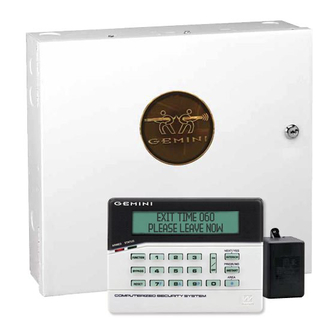
Control panel/communicator
Hide thumbs
Also See for GEMINI GEM-P3200:
- Programming instructions manual (76 pages) ,
- Installation instructions manual (68 pages) ,
- Addendum (2 pages)
Table of Contents
Advertisement
Publicly traded on NASDAQ
Symbol: NSSC
HARDWIRE
CONTROL PANEL/COMMUNICATOR
"Classic" GEM-RP1CAe2 Keypad and the "K Series" GEM-K1CA Keypad
G E M I N I
SYSTEM READY
01/01/06
A
1
B
4
C
7
C O M P UT E R I ZE D S E C U R I T Y SY S T E M
"Classic" GEM-RP1CAe2
Quick Start (for "Classic" GEM-RP1CAe2)
1. Refer to the wiring diagram, connect Siren, Aux. Power,
PGM Output, Remote Bus, Earth ground, Zone and Tele-
phone wiring.
NOTE:
(WI817).
2. Connect AC power first and then the battery.
3. Configure the keypad (see page 55).
4. Access the Easy Menu Driven (Dealer Program) Mode:
Press
EEEEEE
Master Security Code
(on microshield)
Press NO (
) until "ACTIVATE PROGRAM Y/N" appears on the
g
keypad display.
Press YES (
) to Enter Dealer Program Mode. Go to page 5.
F
© NAPCO 2005
R
G E M - P 3 2 0 0
Programming the GEM-P3200 Control Panel with the
12:00 AM
NEXT/YES
D
2
3
E
PRIOR/NO
F
5
6
AREA
8
9 0
G
See Installation Instructions
A
PROGRAMMING
INSTRUCTIONS
G E M I N I
C O M P UT E R I ZE D S E C U R I T Y S Y S T E M
Quick Start (for "K-Series" GEM-K1CA)
1. Refer to the wiring diagram, connect Siren, Aux. Power,
PGM Output, Remote Bus, Earth ground, Zone and Tele-
phone wiring.
(WI817).
2. Connect AC power first and then the battery.
3. Configure the keypad (see page 55).
4. Access the Easy Menu Driven (Dealer Program) Mode:
Press
EEEEEE
Press NO (
Q
keypad display.
Press YES (
P
WIRELESS
SYSTEM READY
01/01/06
12:00 AM
U
R
1
2
3
B
4
5
6
C
7
8
9 0
"K Series" GEM-K1CA
NOTE:
See Installation Instructions
Master Security Code
(on microshield)
) until " ACTIVATE PROGRAM Y/N " appears on the
) to Enter Dealer Program Mode. Go to page 5.
NEXT/YES
P
PRIOR/NO
Q
AREA
G
R
WI818G 10/05
Advertisement
Table of Contents

Related Manuals for NAPCO GEMINI GEM-P3200


Summary of Contents for NAPCO GEMINI GEM-P3200
- Page 1 Publicly traded on NASDAQ Symbol: NSSC HARDWIRE CONTROL PANEL/COMMUNICATOR Programming the GEM-P3200 Control Panel with the "Classic" GEM-RP1CAe2 Keypad and the "K Series" GEM-K1CA Keypad G E M I N I SYSTEM READY 01/01/06 12:00 AM C O M P UT E R I ZE D S E C U R I T Y SY S T E M "Classic"...
-
Page 2: Important Note
THIS MANUAL INCLUDES FEATURES WHICH ARE ONLY AVAILABLE IN CONTROL PANEL FIRMWARE VERSION 50 OR LATER. This manual supports the keypad programming of the GEM-P3200 control panel with the NAPCO "classic" GEM- RP1CAe2 keypad as well as the GEM-K1CA "K Series" keypad. The new "K Series" GEM-K1CA model offers the new STAY and AWAY buttons with simplified functionality, along with the new MENU and ENTER buttons. -
Page 3: Table Of Contents
WI818G 10/05 TABLE OF CONTENTS IMPORTANT NOTE ... 2 CHANGES FROM PREVIOUS EDITION ... 2 SYSTEM PROGRAMMING OPTIONS ... 4 Introduction ... 4 Downloading from a Computer ... 4 EASY MENU DRIVEN PROGRAM MODE ... 5 Dealer Program - Preliminary Information ... 5 Accessing Dealer Program Mode ... -
Page 4: System Programming Options
Page 4 SYSTEM PROGRAMMING OPTIONS INTRODUCTION The GEM-P3200 control panel may be programmed by various means, each of which will be covered in detail in the sections that follow. Keypad displays shown are for a GEM-K1CA (v.8), the recommended keypad for programming. Downloading From a Computer. -
Page 5: Easy Menu Driven Program Mode
WI818G 10/05 EASY MENU DRIVEN PROGRAM MODE DEALER PROGRAM - PRELIMINARY INFORMATION Only Keypad #1 may be used for both dealer and user programming, however this keypad may be located in any area. The Master Security Code is printed on the panel’s microprocessor can. Use this code to enter the Dealer Program Mode to program a custom Dealer Security Code. -
Page 6: Gem-Rp1Cae2/Gem-K1Ca Keypad Easy Program Menu
Page 6 GEM-RP1CAe2/GEM-K1CA Keypad Easy Program Menu o create a custom program using the GEM-RP1CAe2/GEM-K1CA keypad, simply answer the following questions and re- cord your information on the Easy Menu Programming Worksheet. In each of the following steps, press the NEXT/YES button to go forwards, the PRIOR/NO button to go backwards, Total Number of Zones in Area 1 (New Program Only) # o f Z n s i n A r e a 1 •... - Page 7 WI818G 10/05 Chime 2 Zones in Area 1 C h i m e 2 Z o n e s • Enter the zone numbers which are to be used as Chime 2 Zones. E n t e r Z o n e # °...
- Page 8 Page 8 Enable SIA CP-01 Features? • Enable SIA CP-01? Press the NEXT/YES button to enable. • Press the PRIOR/NO button to continue. The SIA CP-01 Features are designed to reduce the incidence of false alarms. NOTE: (Press YES or NO) unless reporting, otherwise system trouble Fail to Communicate may occur.
- Page 9 WI818G 10/05 Central Station Receiver 1 Account Number • Central Station • Account # (____) • (Direct Entry) NOTE: Central Station Receiver 2 and 3 Account Numbers must be entered in Direct Address Pro- gramming. See CS Reporting Options. Central Station Receiver 1 Format •...
- Page 10 Page 10 E n t e r u s e r c o d e 0 0 1 1 2 3 - E 3 - User# User Code Press the button to set the cursor to the User Code. Use the number buttons a code from 3 to 6 digits.
- Page 11 WI818G 10/05 USER AUTHORITY LEVEL NOTES: KEYPAD DISPLAY FUNCTION MENU FUNCTION LEVEL* ** Level-3 Code with appropriate user option DISPLAY ZN FAULTS *** Requires Dealer Code DISPLAY ZN BYPASSED DISPLAY ZN DIRECTORY ACTIVATE BELL TEST DISPLAY PHONE #’S DISPLAY SYS TRBL DISPLAY FIRE ALARM DISPLAY FIRE TRBL DISPLAY OP/CL...
- Page 12 Page 12 E n t e r u s e r c o d e 0 0 1 1 2 3 4 5 6 - 6 - User# User Code number buttons through for each user code. Valid entries are: 0-9. Note: Press the leave blank (•) any trailing boxes.
- Page 13 WI818G 10/05 RF Transmitter Points (Press Z N # X M I T # + C S P For each transmitter enter: (For wireless systems only. Also see Quick Method, which follows) Z n 0 1 - 0 0 0 0 0 0 : 0 - 0 •...
- Page 14 Page 14 KeyFob Transmitters as Zone Input Devices (Refer to display above: press the PRIOR button to go backwards). Each of the 4 keyfob buttons can be assigned to a zone. For example, On button = point 1; Off button = point 2;...
-
Page 15: Direct Address Program Mode
WI818G 10/05 DIRECT ADDRESS PROGRAM MODE DIRECT ADDRESS OVERVIEW Direct Address Programming allows you to go directly to the address locations (up to 4095) and change the data entries manually in order to customize your control panel options. Whereas the Easy Menu Program Mode guides you through limited selections to get you started, Direct Address Program Mode allows you to change all options directly. -
Page 16: Decimal Format Example
Page 16 ZONE FEATURES ADDR Z1 Z2 Z3 Z4 Z5 Z6 Z7 Z8 Exit/Entry Follower 1218 PROGRAM THE DATA ENTRIES 1. Enter the panel's Dealer Security Code, then press 2. Answer NO to all questions until “ACTIVATE PROGRAM Y/N” is displayed; then press YES. NOTE: If you pass “ACTIVATE PROGRAM”, scroll backward using 3. -
Page 17: Hexadecimal Format Example
WI818G 10/05 advance to the data field. 5. Press . The numbers 015 will appear on the keypad display indicating the number of seconds entered. 6. Press to save. Address 2406 is now programmed with a 15-second Abort Delay. 7. Enter another 4-digit address to continue programming or press operation. -
Page 18: Programming Conventions Used In This Manual
Page 18 PROGRAM THE DATA ENTRIES 1. Enter the panel's Dealer Security Code, then press 2. Answer NO to all questions until “ACTIVATE PROGRAM Y/N” is displayed; then press YES. NOTE: If you pass “ACTIVATE PROGRAM”, scroll backward using 3. Press to enter the Address Program Mode. -
Page 19: Programming Options & Worksheets
WI818G 10/05 SYSTEM DELAYS & TIMEOUTS (ADDRESS 0000-0002, 2402, 2406, 2414 & 3902) ADDRESS 0000 ADDRESS 0001 ENTRY EXIT DELAY 1 DELAY (sec.) (sec.) [Default = 060] [Default = 030] Select delay/timeout (0-255 seconds). EXIT/ENTRY DELAYS: Apply only to zones programmed with the following options “Exit/Entry 1, Exit/Entry 2, Exit/Entry Follower”. -
Page 20: System Delays & Timeouts
Page 20 SYST EM DE LA YS & TIMEOU TS ( ADDRESS 2400, 2401, 2403-2405, 4082 & 4083) ADDRESS 2401 ADDRESS 2400 Reset Output Aux. Output Timeout Timeout (min.) (min.) [Default = 000] [Default = 000] 1. Select delay/timeout (0-255 min.). 2. -
Page 21: Cs Receiver Format Options
WI818G 10/05 C S R EC EI VE R FO RM A T O PTIO NS ADDRESS 0525 CS Receiver 1 Format Default for CS Receiver 1 Format depends on Easy Menu Question “RCVR FORMAT”. [Default = •(blank) E] for CS Receivers 1, 2 and 3 Formats. DATA ENTRIES CS RECEIVER FORMATS LEFT... -
Page 22: Cs Receiver Telephone Numbers
Page 22 CS RECEIVER T ELEPH ONE NUMBERS CS Receiver 1 Telephone 0527 0528 0529 0530 0531 0532 0533 0534 0535 0536 0537 0538 0539 0540 0541 0542 0543 0544 0545 0546 Number (Digits 1-20) CS Receiver 2 Telephone 0552 0553 0554 0555 0556 0557 0558 0559 0560 0561 0562 0563 0564 0565 0566 0567 0568 0569 0570 0571 Number (Digits 1-20) CS Receiver... -
Page 23: Cs Subscriber Id Numbers (Address 0650-0787)
WI818G 10/05 CS SUBSCRIBER ID NUMBERS (A DDRESS 0 6 50 -0 78 7) CS TELCO 1 SUBSCRIBER OPENING/CLOSING ID NUMBERS AREA 1 AREA 2 ADDRESS 0650-0653 ADDRESS 0654-0657 (DIGITS 1-4) (DIGITS 1-4) 0650 0651 0652 0653 0654 0655 0656 0657 CS TELCO 1 SUBSCRIBER EVENT ID NUMBERS AREA 1 AREA 2... -
Page 24: Cs Subscriber Id Numbers (Address 0790-0857)
Page 24 C S SUBSCRIBER ID NUMBERS (A DDRESS 0 79 0-08 5 7) CS TELCO 3 SUBSCRIBER OPENING/CLOSING ID NUMBERS AREA 1 AREA 2 ADDRESS 0790-0793 ADDRESS 0794-0797 (DIGITS 1-4) (DIGITS 1-4) 0790 0791 0792 0793 0794 0795 0796 0797 CS TELCO 3 SUBSCRIBER EVENT ID NUMBERS AREA 1 AREA 2... -
Page 25: Cs Reporting Codes (Address 0870-0904)
WI818G 10/05 CS REPOR TIN G CODES (ADDRESS 0870-0904) ADDRESS SYSTEM REPORTING 0870-0880 CODES LEFT ADDR RIGHT Test Timer 0870 Alarm Supervisory 0871 Bus Failure 0872 Memory Failure 0873 Low Battery 0874 AC Failure 0875 EZM Tamper 0876 Sensor Watch 0877 RESERVED blank (•) -
Page 26: Cs Zone Reporting Codes (Address 0910-0957)
Page 26 CS ZON E REP OR TING C ODES (A DDRESS 0 91 0-09 57) ADDRESS 0910-0917 ZONES REPORT CODE (CONTROL PANEL) ZONE 1 ZONE 2 ZONE 3 ZONE 4 ZONE 5 ZONE 6 ZONE 7 ZONE 8 0910 0911 0912 0913... -
Page 27: Cs User Reporting Codes (Address 1030-1074)
WI818G 10/05 CS USER REP OR TING C ODES (A DDRESS 1 0 30 -1 07 4) ADDR U1 U2 U3 U4 U5 U6 U7 U8 Enable Users to Report 1030 User Opening Telco 1 1043 User Closing Telco 1 1056 User Opening Telco 3 1069... - Page 28 Page 28 GLOBAL SYS TE M TR OUBLE RE P ORTIN G OPT IONS (ADDRES S 1082-1116) SYSTEM RESPONSE ACTIVATED BY GLOBAL EVENT/TROUBLE Burglary Alarm Output Pulsed Burg. Output Fire Output (Lug E9) Reset Relay Auxiliary Relay Report Event Telco 1 Report Restore Telco 1 Report Event Telco 3 Report Restore Telco 3...
-
Page 29: Area System Trouble Reporting Options (Address 1120-1137)
WI818G 10/05 AREA SYST EM T ROUBLE R EPORTING OP TI ONS (ADD RESS 11 20 -1 137 ) SYSTEM RESPONSE ADDR ACTIVATED BY AREA 1 EVENT/TROUBLE Pulsed Burg. Output 1120 Burglary Output 1121 Fire Output (Lug E9) 1122 Reset Relay 1123 Auxiliary Relay 1124... -
Page 30: Zone Options / Zones 1-16 (Address 1200-1386)
Page 30 ZONE OPTI ONS / ZONE S 1-16 (AD DRESS 120 0 -13 8 6) ZONE OPTIONS ADDR Z1 1200 50ms Loop Response (A) 1201 20ms Loop Response (A) Priority 1202 Priority with Bypass 1203 Auto-Bypass 1204 Selective Bypass 1205 Keyswitch Arming 1206... -
Page 31: Zone Options / Zones 17-32 (Address 1402-1586)
WI818G 10/05 ZONE OPTI ONS / ZONE S 17 -32 (A DDRESS 1 40 2 -1 58 6) ZONE OPTIONS ADDR Z17 Z18 Z19 Z20 Z21 Z22 Z23 Z24 ADDR Z25 Z26 Z27 Z28 Z29 Z30 Z31 Z32 Priority 1402 Priority with Bypass 1403 Auto-Bypass... -
Page 32: Zone Options / Zones 33-48 (Address 1602-1786)
Page 32 ZONE OPTI ONS / ZONES 33 -48 (A DDRESS 1 6 02 -1 78 6) ZONE OPTIONS ADDR Z33 Z34 Z35 Z36 Z37 Z38 Z39 Z40 ADDR Z41 Z42 Z43 Z44 Z45 Z46 Z47 Z48 Priority 1602 Priority with Bypass 1603 Auto-Bypass 1604... - Page 33 WI818G 10/05 ZON E O PTI ONS / ZONE S 1- 4 8 (AD DRESS 12 0 0-1 7 86 ) ZONE OPTIONS: Select zone options for any zone. Select the desired zone option by entering the option number (1-8) for each selected zone. Enter corresponding option number in address location, in Binary (Bit) Format.
-
Page 34: System Options (Address 2415-2419)
Page 34 SYST EM OPTION S (ADDRES S 2415-2419) 2415 System Options - Disable Fire Reset Option Default Disable Fire Reset (Area 1) Disable Fire Reset (Area 2) RESERVED RESERVED RESERVED RESERVED RESERVED RESERVED 2417 System Options Option Default Opening Report only after Alarm Report Closing Report only on Cond. -
Page 35: System Options (Address 2420-2422, 3874, 3905, 3880-3881)
WI818G 10/05 SYST EM OPT ION S (AD DRES S 24 20 -2 4 22, 387 4, 3 90 5, 38 8 0-38 81 ) 2420 System Options Option Default Disable System Trouble Audible (at Keypad) Chime on Lug E4 Disable Code required for Func. -
Page 36: System Options (Address 3882-3901, 3903-3905 & 4084)
Page 36 SYST EM OPT ION S (A DDRES S 3882-3901, 3903-3905 & 4084) Telephone Dialing 3882 3883 3884 3885 3886 3887 3888 3889 3890 3891 3892 3893 3894 3895 3896 3897 3898 3899 3900 3901 Prefix (Digits 1-20) LEFT DATA SYSTEM OPTIONS VALUES RESERVED... -
Page 37: Keypad Options (Address 2425-2446)
WI818G 10/05 KEYPA D OPTION S (ADDRES S 2425-2446) ADDRESS 2425 Keypad 1 Type Keypad 2 Type LEFT RIGHT & Area & Area Assignment Assignment [Default = blank (•) 1] [Default = blank (•) blank (•)] ADDRESS 2429 Keypad 5 Type Keypad 6 Type LEFT RIGHT... -
Page 38: Acm Zone Options (Address 2740-2769)
Page 38 ACM ZONE OPTI ONS (ADDRESS 2740-2769) ACM ZONE OPTIONS: Enter the Zone numbers (in decimal 1-48 format) for each option in the table below. Press NOTE: Dark shaded data value box shows option not available. Note: The Area # for Door 1 is controlled by the ex- isting Keypad Programming table (Address 2425 to 2431). -
Page 39: Acm Door Area Options (Address 2784-2787)
WI818G 10/05 ACM D OOR ARE A OPTION S (AD DRESS 278 4-27 8 7) ACM DOOR AREA OPTIONS: Select the desired option entering the option number (1-3) for each address. Enter corresponding option number in address location. NOTE: Dark shaded data value box shows option not available. Press ACM Door Number ACM 1 - Door 1 ACM 1 - Door 2... -
Page 40: Keypad Home Area / Acm Door #1 Area (Hex) (Address 2425-2431)
Page 40 KEYPAD HOME AREA / ACM DOOR #1 AR EA (HE X) ACM ZONE OPTIONS: Enter the Zone numbers (in two-digit hexadecimal format) for each option in the table below. The left digit (nibble) determines the type of device: "●" for Keypad and "1" for ACM. The right digit (nibble) determines the home area (1 or 2) of the specified device. -
Page 41: System Options (Address 2423)
WI818G 10/05 SYST EM OPTION S (ADDRES S 2423) SYSTEM OPTION: Select the System Option from the table shown and enter in the corresponding address location at right. Keypad Blank- ing will clear all data from the LCD display (and turn off all keypad LED's) after the system is armed and delay time has ex- pired. -
Page 42: User Area Options (Address 2455-2502)
Page 42 USER AREA OPTIONS (ADDRESS 2455-2502) USER NUMBER USER AREA OPTIONS: Each address corresponds to a specific User, numbered 1-48. For each User, select the desired Area by marking the desired Area number (1 or 2) in the above table. Enter the corresponding Area number in each the address location, in Binary (Bit) Format. -
Page 43: Ezm Group Options (Address 2555-2576)
WI818G 10/05 EZM GR OUP OPTIONS (ADDRE S S 2555- 2576) EZM Group 1 EZM Group 2 ZONES 9-12 ZONES 13-16 ADDRESS 2555 ADDRESS 2556 Default depends on Easy Menu questions: "# OF ZNS IN AREA1" "# OF ZNS IN AREA2" For example, If 32 zones are used, then all 6 groups will be automatically enabled. -
Page 44: Area Arming Options (Address 2650-2651)
Page 44 AREA ARMING OPTI ONS (ADDRE SS 2650-2 651) ARMING AREA [Default = blank (•) blank (•) from address 2650-2651] PRIORITY AREA ARMING: 1. Select the desired arming area. 2. Enter the corresponding Area number in each the address location, in Binary (Bit) Format. NOTE: See Direct Address Programming Example on page 15. -
Page 45: Area Output Control Options (Address 2700-2739)
WI818G 10/05 AREA OUT PUT C ONTR OL OP TI ON S (ADDRES S 2700-2739) OUTPUT SILENCED (TURNED OFF) ADDR Burglary Output 2700 Pulsed Burg. Output 2708 Fire Output 2716 Reset Relay 2724 Auxiliary Relay 2732 [Default = Noted above with "ON"] AREA OUTPUT TURNS OFF UPON DISARM: Select options for any of the 5 Outputs per area when disarming a particular area. -
Page 46: Rf Receivers & Supervisory Timer Options
Page 46 RF RECEIVER S & SUPERVIS ORY TIMER OP TI ONS DATA ADDRESS 3776 Number of RF ENTRIES Receivers Default Number of Receivers = 0 RF SUPERVISORY RF TRANSMITTER TIMER Type 0 Window/Door, 2 Pt. Type 1 Window/Door, 2 Pt. Type 2 Window/Door, 2 Pt. -
Page 47: External Relay Control / Relays
WI818G 10/05 EXTERNAL RELAY CONTR OL / R ELAYS 1-24 (RELAY/entry 1) ADDRESS 3778 & 2800-2803 3778 2800 2801 2802 2803 (RELAY/entry 4) ADDRESS 3781 & 2812-2815 3781 2812 2813 2814 2815 (RELAY/entry 7) ADDRESS 3784 & 2824-2827 3784 2824 2825 2826 2827... - Page 48 Page 48 To program, follow the 5 steps below: STEP 1: RELAY # OPTIONS: Each relay/entry can be assigned to any of the 24 available external relays from Relay Module RM3008. Multiple entries can drive the same External Relay. Select the relay number from Table 1 (shown on next page); enter in corresponding left and right digit address locations.
- Page 49 WI818G 10/05 Table 1 below TABLE 1 RELAY MAPPING DATA ENTRIES RELAY # LEFT RIGHT blank (•) blank (•) None * blank (•) blank (•) blank (•) blank (•) blank (•) blank (•) blank (•) blank (•) blank (•) blank (•) blank (•) blank (•) blank (•)
- Page 50 Page 50 STEP 4: EVENT ID CODES: Each relay event can be assigned any of the available event IDs from the table. Select 2-digit Event ID from Table 4 (below); enter in corresponding address locations (left and right digit). TABLE 4 EVENT ID CODES DATA ENTRIES LEFT...
-
Page 51: Number Of Relay Board Modules (Address 3777)
WI818G 10/05 STEP 5: RELAY EVENT CONDITION OPTIONS: timeout type for each. 5A. Select Alarm Type and Timeout Type from Table 5A (below); enter in corresponding address location (left digit). NOTE: Select Timeout from Step 3. 5B. Select Activation from from Table 5B (below); enter in corresponding address location (right digit). TABLE 5A RELAY EVENT ALARM TYPE OPTIONS... -
Page 52: System Reset Options (Address 4091-4093)
Page 52 SYST EM RES ET OPT ION S (A DDR ESS 40 9 1-40 93 ) 4091 XX GEM-RP1CAe2/GEM-K1CA Keypad GEM-RP2ASe2 Keypad 4091XX 4093 XX GEM-RP1CAe2/GEM-K1CA Keypad GEM-RP2ASe2 Keypad 4093XX USER PROGRAM MODE PRELIMINARY INFORMATION The User Program Mode is covered in detail in the operating instructions for the keypad in use. Only Keypad #1 may be used for programming, however this keypad may be located in either area. -
Page 53: Accessing User Program Mode
WI818G 10/05 ACCESSING USER PROGRAM MODE 1. Press EEEEEE Existing Panel (Any Code with User Program Option Enabled) 2. Press Q 3. Press P 4. Press C USER CODES Enter user code U01 123 GEM-K1CA Keypad (Direct Entry) Up to 48 User Codes may be programmed. NOTE: In this mode, only the code is pro- grammable;... -
Page 54: Zone Descriptions
Page 54 ZONE DESCRIPTIONS (GEM-RP1CAE2 / GEM-K1CA KEYPADS) (Direct Entry) PRESS: CHARACTERS DISPLAYED IN SEQUENCE ABC1 DEF2 GHI3 JKL4 MNO5 PQR6 STU7 VWX8 YZ90 (SPACE) - . ( ) , / : ? # Press [ ] to move cursor right. Press [ ] to move cursor left. -
Page 55: Keypad Configuration Mode
WI818G 10/05 KEYPAD CONFIGURATION MODE This section will focus on configuring the GEM-RP1CAe2/GEM-K1CA Keypads. If there is more than one keypad in the system, only Keypad No. 1 may be used for programming. KEYPAD INSTALLATION Two types of keypads may be used with the GEM-P3200: the GEM-RP1CAe2/GEM-K1CA. Each must be assigned an address number (1–7) and each requires its own configuration procedure (see CONFIGURING THE KEYPADS, which follows, and DIRECT ADDRESS KEYPAD AREA OPTIONS). - Page 56 Page 56 Compat # 0000 EZM Address Workbook) similar to its keypad address. If no other EZMs are to be used, designate the keypad as Group “01” at the “ ” display. In multiple-EZM systems, enter an assigned group number “01” through “06”. (Each EZM ADDRESS 00 EZM must have a unique assigned group number, starting with “01”...
-
Page 57: Alphabetical Index
WI818G 10/05 ABORT DELAY ADDRESS 2406, 19 ABORT DELAY ZONE OPTION, 30, 31, 32 AC FAIL REPORT DELAY ADDRESS 2408, 19 ACCESS CONTROL (PANEL) ON AUX. OUTPUT ADDRESS 2418, 34 ACCESS CONTROL OPTIONS, 10 ACCESSING DEALER PROGRAM MODE, 5 ACCESSING USER PROGRAM MODE, 53 ACM DOOR #1 AREA (HEX) (ADDRESS 2425-2431), 40 ACM DOOR AREA OPTIONS (ADDRESS 2784-2787), 39 ACM GLOBAL FLAGS (ADDRESS 2780), 38... - Page 58 Page 58 ALPHABETICAL INDEX (CONT'D) DIALING—ROTARY OR TOUCH-TONE, 25 DIGITAL DIALER RPT ENTER/EXIT TEST MODE ADDRESS 3905, 35 DIRECT ADDRESS OVERVIEW, 15 DIRECT ADDRESS PROGRAM MODE, 15 DISABLE AC FAIL DETECTION ADDRESS 2420, 35 DISABLE ANSWERING-MACHINE DOWNLOAD ADDRESS 2419, 34 DISABLE AREA ENTRY RELAYS ADDRESS 2422, 35 DISABLE AUTO-RESET ON DAY ZONE ADDRESS 2419, 34 DISABLE AUTO-UNBYPASS ON DISARMING ADDRESS 2417, 34...
- Page 59 WI818G 10/05 1400HZ HANDSHAKE/KISSOFF ADDRESS 0576, 21 FUNCTION MODE, 4 GEM-RP1CAE2/GEM-K1CA KEYPAD EASY PROGRAM MENU, 6 GENERAL PROGRAMMING STEPS, 18 GLOBAL SYSTEM EVENT/TROUBLE, 28 GLOBAL SYSTEM TROUBLE REPORTING OPTIONS (ADDRESS 1082-1116), 28 HANDSHAKE FOR LOCAL TELEMETRY ADDRESS 1027, 25 HEXADECIMAL FORMAT, 17 INCLUDE SEL./GRP.
- Page 60 Page 60 ALPHABETICAL INDEX (CONT'D) RPT TROUBLE RESTORE TEL 1 ZONE OPTION, 30, 31, 32 RPT TROUBLE RESTORE TEL 3 ZONE OPTION, 30, 31, 32 RPT TROUBLE TEL 1 ZONE OPTION, 30, 31, 32 RPT TROUBLE TEL 3 ZONE OPTION, 30, 31, 32 SCHEMATIC, 68 SELECT BELL OUTPUT ON KEYFOB ARMING ADDRESS 2422, 35 SELECTIVE BYPASS ZONE OPTION, 30, 31, 32...
-
Page 61: Address Number Index
WI818G 10/05 ADDRESS 0000 ... EXIT DELAY ...19 ADDRESS 0000-0002 ... SYSTEM DELAYS & TIMEOUTS ...19 ADDRESS 0001 ... ENTRY DELAY 1 ...19 ADDRESS 0002 ... ENTRY DELAY 2 ...19 ADDRESS 0490-0492 ... PANEL ACCESS CODE ...20 ADDRESS 0490-0495 ... KEYPAD SYSTEM CODES ...20 ADDRESS 0495 ... - Page 62 Page 62 WI818G 10/05 ADDRESS NUMBER INDEX (CONT'D) ADDRESS 0577-0596 ... CS RECEIVER TELEPHONE NUMBERS ...22 ADDRESS 0600-0619 ... DOWNLOAD/CALLBACK OPTIONS ...22 ADDRESS 0625-0647 ... DOWNLOAD/CALLBACK OPTIONS ...22 ADDRESS 0645-0647 ... DOWNLOAD SECURITY CODE ...22 ADDRESS 0650-0787 ... CS SUBSCRIBER ID NUMBERS ...23 ADDRESS 0790-0857 ...
- Page 63 WI818G 10/05 ADDRESS 2408 ... AC FAIL REPORT DELAY ...19 ADDRESS 2408 ... SYSTEM DELAYS & TIMEOUTS ...19 ADDRESS 2414 ... SYSTEM DELAYS & TIMEOUTS ...19 ADDRESS 2414 ... TELEPHONE LINE TEST DELAY ...19 ADDRESS 2415 ... DISABLE FIRE RESET ...34 ADDRESS 2415-2419 ...
- Page 64 Page 64 WI818G 10/05 ADDRESS NUMBER INDEX (CONT'D) ADDRESS 2421 ... VERI-PHONE ZONES PRIORITY OVER ALARMS ...35 ADDRESS 2421 ... VERI-PHONE ZONES TRIP AUX. OUTPUT ...35 ADDRESS 2421 ... VERI-PHONE ZONES TRIP FIRE OUTPUT ...35 ADDRESS 2422 ... DISABLE AREA ENTRY RELAYS ...35 ADDRESS 2422 ...
- Page 65 WI818G 10/05 ADDRESS 3874 ... ENABLE SET TIME/DATE MESSAGE ...35 ADDRESS 3874 ... SYSTEM OPTIONS ...35 ADDRESS 3874 ... SYSTEM OPTIONS ...35 ADDRESS 3874 ... WIRELESS TROUBLE TO TELCO 1 ...35 ADDRESS 3874 ... WIRELESS TROUBLE TO TELCO 3 ...35 ADDRESS 3880 ...
- Page 66 Page 66 WI818G 10/05 NOTES NAPCO Security Systems GEM-P3200 Programming Instructions...
- Page 67 Page 67 WI818G 10/05 NOTES NAPCO Security Systems GEM-P3200 Programming Instructions...
-
Page 68: Gem-P3200 Wiring Diagram
Page 68 WI818G 10/05 GEM-P3200 WIRING DIAGRAM NAPCO Security Systems GEM-P3200 Programming Instructions...