Table of Contents
Advertisement
Quick Links
Advertisement
Table of Contents

Related Manuals for E-FLITE Mini Pulse XT


Summary of Contents for E-FLITE Mini Pulse XT
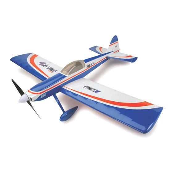
- Page 1 Mini Pulse XT Assembly Manual...
-
Page 2: Table Of Contents
Table of Contents Introduction..............3 Non-Warranty.Repairs..........10 Specifications..............3 Safety,.Precautions,.and.Warnings......11 Using.the.Manual............3 Landing.Gear.Installation..........12 Contents.of.Kit/Parts.Layout..........4 Outrunner.Motor.Installation........14 Required.Radio.Equipment..........5 Cowling.Installation...........15 Important.Information.About.Motor.Selection....6 Tail.Installation............19 Sport.Outrunner.Setup..........6 Wing.Preparation............24 Optional.Accessories...........6 Final.Assembly............26 Required.Tools.and.Adhesives........6 Control.Throws............30 Note.Regarding.Hinges..........7 Range.Testing.the.Radio..........31 Note.on.Lithium.Polymer.Batteries........7 Center.of.Gravity............31 Warning..............7 Preflight..............32 Limited.Warranty.Period..........8... -
Page 3: Introduction
Thank you for purchasing the Mini Pulse XT. Designed This manual is divided into sections to help make assembly from the beginning for electric power, the Mini Pulse XT easier to understand, and to provide breaks between each is developed from the Hangar 9 ®... -
Page 4: Contents.of.kit/Parts.layout
Tail Set EFL2380 Main Landing Gear EFL2381 Cowling EFL2382 Wheel Pants Small Replacement Parts: EFL2379 Pushrod Set EFL2383 Motor X-Mount EFLA200 Micro Control Horns FLA203 Micro Control Connectors EFLA219 Steerable Tailwheel Assembly EFLA223 Foam Park Wheels, 2" EFLA213 E-flite/JR/Horizon Decals... -
Page 5: Required.radio.equipment
Required Radio Equipment You will need a minimum 4-channel transmitter, crystals, micro receiver, and four sub-micro servos. You can choose JSP30610 6-Channel UltraLite Rx w/o Crystal, Positive Shift JR/AIR (72MHz) to purchase a complete radio system that includes all of these items or, if you are using an existing transmitter, just purchase the other required equipment separately. -
Page 6: Important.information.about.motor.selection
890Kv (EFLM1400) to provide you with excellent sport Required Tools and Adhesives and aerobatic power and a worry-free outrunner motor. The Mini Pulse XT does not include a propeller, but we Tools & Equipment recommend our 10X8 Electric Prop (EFLP1080E). -
Page 7: Note.regarding.hinges
Note Regarding Hinges Note on Lithium Polymer Batteries For your convenience and to speed the assembly process, Lithium Polymer batteries are significantly the hinges have already been installed and glued. We more volatile than alkaline or Ni-Cd/Ni-MH suggest that you take a minute before beginning assembly batteries used in RC applications. -
Page 8: Limited.warranty.period
Limited Warranty Period all equipment involved in a warranty claim. Repair or replacement decisions are at the sole discretion of Horizon Horizon Hobby, Inc. guarantees this product to be free Hobby, Inc. Further, Horizon Hobby reserves the right to from defects in both material and workmanship at the change or modify this warranty without notice. -
Page 9: Safety.precautions
Safety Precautions Questions or Assistance This is a sophisticated hobby product and not a toy. It For questions or assistance, please direct your email to must be operated with caution and common sense and productsupport@horizonhobby.com, or call 877.504.0233 requires some basic mechanical ability. Failure to operate toll-free to speak to a service technician. -
Page 10: Warranty.inspection.and.repairs
Warranty Inspection and Repairs Non-Warranty Repairs Should your repair not be covered by warranty and the To receive warranty service, you must include your expense exceeds 50% of the retail purchase cost, you will original sales receipt verifying the proof-of-purchase be provided with an estimate advising you of your options. -
Page 11: Safety,.Precautions,.And.warnings
Safety, Precautions, and Warnings As the user of this product, you are solely responsible for • Avoid operating your model in the street where injury or operating it in a manner that does not endanger yourself damage can occur. and others or result in damage to the product or the •... -
Page 12: Landing.gear.installation
Landing Gear Installation 1. Place the landing gear onto the bottom of the fuselage. They will angle back slightly when Required Parts installed in the correct direction. Attach with Fuselage two 4-40 x 1/2" socket head bolts and two #4 Main landing gear black washers. - Page 13 2. Slide the 4-40 x 1 " socket head bolt 3. Fit the assembly in Step 2 into the wheel pant through one of the 2" wheels. Slide a #4 steel and insert the bolt into the landing gear. With washer so it fits against the wheel.
-
Page 14: Outrunner.motor.installation
The wider section of the mount will be Fuselage positioned towards the motor wires. Brushless motor 4-40 x 1 " socket head screw (4) Aluminum motor spacer, 13/16" (20mm) (4) Required Tools and Adhesives Hex wrench: 3/32" Screwdriver (Phillips #0) Note:.This.section.covers.the.installation.of. the.recommended.Park.450.Outrunner.motor.. The.holes.in.the.firewall.for.mounting.the. custom.X-mount.will.also.fit.the.hole.pattern.for. our.E-flite®.Firewall.Stick.Mount.(EFLM1916. –.available.separately).if.you.prefer.to.use.a. gearbox.with.an.inrunner.motor. -
Page 15: Cowling.installation
Cowling Installation 2. Attach the Outrunner motor to the front of the firewall using four 4-40 x 1 " socket head Required Parts screws and the aluminum motor spacers. Fuselage w/motor installed Cowling 2mm x 8mm wood screw (4) Propeller Spinner Prop adapter (for outrunner motor) - Page 16 Important Information About Your Propeller 1. Solder any connectors to the speed control to connect to the motor battery and motor if It is also very important to check to be sure the necessary. Connect the ESC to the motor and propeller is balanced before installing onto the shaft.
- Page 17 4. Slide the cowling onto the fuselage. Install the 2. Connect the speed control to the radio system propeller adapter onto the Outrunner shaft. You and motor battery. Check that the motor is may need to ream out the hole on your prop hub rotating in the correct direction.
- Page 18 Note:.Make.sure.to.check.the.balance.of. 6. Enlarge the holes in the cowl using a 5/64" the.propeller.after.enlarging.the.hole.in.the. (2mm) drill bit. Secure the cowl using four propeller. 2mm x 8mm sheet metal screws. Snap the spinner cone onto the spinner backplate once the cowl is secure. ...
-
Page 19: Tail.installation
Tail Installation 1. Attach the tail wheel to the tail gear wire using a 1/16" wheel collar and setscrew. Required Parts Fuselage Rudder/Fin Stabilizer/Elevator Servo (2) Servo extension, 12" (305mm) (2) Control connectors w/backplate (2) 2mm x 4mm screw (2) 4-40 locknut (2) #4 washer (2) Linkage wire, 4"... - Page 20 2. Locate the stabilizer/elevator assembly. Position 3. Slide the rudder/stabilizer assembly onto the the stabilizer/elevator assembly so the control fuselage. Slide the #4 washers onto the threaded horn will face down, away from the fin. The rods. Thread the nuts onto the rod, tightening threaded rods from the rudder/fin assembly will them snugly against the bottom of the fuselage.
- Page 21 4. Attach a 12" (305mm) servo extension to 5. Install the elevator servo into the fuselage a servo lead. Use thread or a commercially using the hardware provided with the servo. available connector to secure the extension to Drill 1/16"...
- Page 22 6. Remove the servo arm from the elevator 7. Repeat Steps 4 through 6 for the rudder servo. servo. Drill a 1/16" (1.5mm) hole through the center hole in the arm. Slide the control connector through the hole and secure it using the connector backplate.
- Page 23 8. Locate the 4" (102mm) linkage wire. Slide the 9. Repeat Step 7 for the rudder linkage. “Z” bend into the center hole of the elevator control horn. Pass the linkage through the pushrod connector on the servo arm. Turn on the radio and plug the elevator servo into the receiver.
-
Page 24: Wing.preparation
Wing Preparation 1. Secure a 6" (152mm) servo extension onto the servo lead. Install the aileron servo into the Required Parts wing, using the pre-installed string to pull the Wing servo lead through the wing. The servo lead will 6-channel receiver exit the hole in the top center of the wing. - Page 25 2. Drill a 1/16" (1.5mm) hole in the servo arm 4. Plug the aileron servo into the receiver. Power for the pushrod connector. Secure the control up the transmitter and receiver. Center the aileron connector in the servo arm using the connector stick, trim, and any programmed sub-trim values.
-
Page 26: Final.assembly
Final Assembly 1. Plug in the elevator and rudder servos and ESC into the receiver. Mount the receiver to the inside Required Parts of the fuselage using hook and loop material. Fuselage Route the antenna wire through the bottom of the Wing fuselage to the rear, or as directed by your radio Canopy... - Page 27 2. Place the canopy into position on the fuselage. 3. Use medium grit sandpaper to roughen the Use a felt-tipped pen to trace the outline of the covering 1/8" (3mm) inside the line drawn. Also canopy onto the fuselage. roughen the outside 1/8"...
- Page 28 4. Use Formula 560 canopy glue to glue the canopy 5. Plug the Y-harness for the aileron servos into to the fuselage. Use masking tape to hold the the receiver. Attach the wing to the fuselage canopy in position until the glue fully cures. using two 4-40 x 1"...
- Page 29 6. With the aircraft fully assembled, install the 7. Install the battery hatch to the top of the fuselage. battery into the battery compartment. Secure the The magnet will hold the battery hatch in place. battery using the hook and loop tape and a hook and loop strap.
-
Page 30: Control.throws
Control Throws Low Rate High Rate 1. Turn on the transmitter and receiver of your Mini Ailerons: Pulse XT. Check the movement of the rudder, Up/Down 3/8" (9mm) 1/2" (13mm) elevator and ailerons using the transmitter. Elevator: Reverse the direction of the servos at the Up/Down 1/4"... -
Page 31: Range.testing.the.radio
1. Be sure to range check your radio before each The recommended Center of Gravity (CG) location for the flying session. This is accomplished by turning Mini Pulse XT is 2 " (70mm) behind the leading edge of on your transmitter with the antenna collapsed. -
Page 32: Preflight
Preflight Check Your Radio Note:.Keep.loose.items.that.can.get.entangled. in.the.propeller.away.from.the.prop..These. Before going to the field, be sure that your batteries are include.loose.clothing,.or.other.objects.such.as. fully charged per the instructions included with your radio. pencils.and.screwdrivers..Especially.keep.your. Charge both the transmitter and receiver pack for your hands.away.from.the.propeller. airplane. Use the recommended charger supplied with Double-check that all controls (aileron, elevator, rudder your particular radio system, following the instructions and throttle) move in the correct direction. -
Page 33: Notes
Notes... -
Page 34: 2006 Official Ama National Model Aircraft Safety Code
2006 Official AMA National Model Aircraft Safety Code GENERAL 6) I will not operate models with metal-bladed propellers or with gaseous boosts, in which gases other than air 1) I will not fly my model aircraft in sanctioned events, enter their internal combustion engine(s); nor will I operate air shows or model flying demonstrations until it has models with extremely hazardous fuels such as those been proven to be airworthy by having been previously,... -
Page 35: Official Ama National Model Aircraft Safety Code
2006 Official AMA National Model Aircraft Safety Code 4) I will operate my model using only radio control 6) For Combat, distance between combat engagement frequencies currently allowed by the Federal line and spectator line will be 500 feet per cubic inch of Communications Commission. - Page 36 ® © 2006 Horizon Hobby, Inc. 4105 Fieldstone Road Champaign, Illinois 61822 (877) 504-0233 horizonhobby.com E-fliteRC.com 9249...