Table of Contents

Related Manuals for E-FLITE Extra 300 32e


Summary of Contents for E-FLITE Extra 300 32e
-
Page 1: Specifications
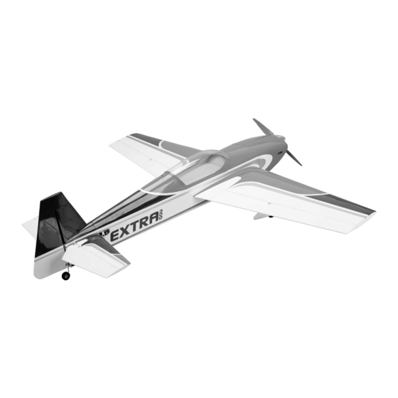
Extra 300 32e ARF Assembly Manual Specifications Wingspan: 52.5 inches (1335mm) Wing Area: 542 sq in (34.2 sq dm) Length: 49.0 inches (1245mm) Weight w/Battery: 4.40 – 4.60 lb (1.90–2.10 kg) Weight w/o Battery: 3.70 – 3.90 lb (1.60–1.80 kg) -
Page 2: Table Of Contents
Designed by veteran IMAC and XFC competitor, Mike This manual is divided into sections to help make Introduction ............2 McConville, the Extra 300 32e ARF is optimized assembly easier to understand, and to provide breaks Important Information Regarding to deliver unlimited 3D and precision aerobatic between each major section. -
Page 3: Recommended Radio Equipment
30C Li-Po EFLSP225 inch Aluminum Spinner Optional Accessories EFLA110 Power Meter EFLC505 Intelligent 1- to 5-Cell Balancing Charger The Spektrum trademark is used with permission of Bachmann Industries, Inc. E-flite Extra 300 32e ARF Assembly Manual... -
Page 4: Aileron Installation
Note that there are five (5) slots, even though only three (3) hinges were removed in the previous step. E-flite Extra 300 32e ARF Assembly Manual... - Page 5 If you find any loose hinges, apply more CA to the hinge and recheck. 12. Repeat Steps 1 through 11 to join the remaining aileron to its wing panel. E-flite Extra 300 32e ARF Assembly Manual...
-
Page 6: Aileron Servo Installation
#2 Phillips screwdriver to keep the control horn screw from rotating when installing the control horn. Prepare the elevator and rudder servos at this time as well. E-flite Extra 300 32e ARF Assembly Manual... - Page 7 Use care not to screwdriver to tighten the screws. accidentally drill through the covering on the top of the wing. E-flite Extra 300 32e ARF Assembly Manual...
- Page 8 16. Repeat Steps 1 through 15 to install the remaining aileron servo. 12. Use a pin vise and a 5/64-inch (2mm) drill bit to enlarge the outer hole in the servo horn. E-flite Extra 300 32e ARF Assembly Manual...
-
Page 9: Motor Installation
Threadlock Phillips screwdriver: #1, #2 Ball driver or hex wrench: 3/32-inch 1. Remove the canopy hatch from the fuselage by sliding the hatch pin rearward and lifting the hatch from the fuselage. E-flite Extra 300 32e ARF Assembly Manual... -
Page 10: Cowling And Spinner Installation
1. Fit the cowling to the fuselage. It should overlap operation of the motor. the fuselage as shown. 5. Secure a 3-inch (76mm) servo extension to the lead from the speed control using string or a commercially available connector. E-flite Extra 300 32e ARF Assembly Manual... - Page 11 4. Slide the propeller on the adapter. It may be necessary to enlarge the hole in the propeller so it fits over the adapter. E-flite Extra 300 32e ARF Assembly Manual...
-
Page 12: Landing Gear And Wheel Installation
If the holes in the landing gear don’t align with the blind nuts in the fuselage, rotate the gear front-to-back so the holes are aligned with the blind nuts installed in the fuselage. E-flite Extra 300 32e ARF Assembly Manual... -
Page 13: Fuselage Servo And Receiver Installation
3/32-inch hex wrench or ball driver. Note: You should have already installed the grommets earlier when you did the aileron servos. If you didn't, please go back to page 6, Step 4 for instructions. E-flite Extra 300 32e ARF Assembly Manual... - Page 14 3. Move the servo from the fuselage. Use a pin vise the fuselage. into the appropriate ports of the receiver at this time. with a 1/16-inch (1.5mm) drill bit to drill the four holes in the fuselage for the servo mounting screws. E-flite Extra 300 32e ARF Assembly Manual...
-
Page 15: Stabilizer Installation
5. Slide the two carbon tubes into one of the stabilizer halves. 3. Use a pin vise with a 5/64-inch (2mm) drill bit to enlarge the outer hole of the elevator servo arm. E-flite Extra 300 32e ARF Assembly Manual... - Page 16 Mix covering 1/16-inch (1.5mm) inside the lines drawn 1/4 ounce (15mL) of 30-minute epoxy. Apply a on the fuselage. small amount of epoxy in the holes of the stabilizer for the stabilizer tubes. E-flite Extra 300 32e ARF Assembly Manual...
- Page 17 Use a paper towel and rubbing alcohol to remove any excess epoxy. Set the fuselage assembly aside until the epoxy has fully cured. E-flite Extra 300 32e ARF Assembly Manual...
-
Page 18: Elevator Installation
Use a #2 Phillips screwdriver and pliers to tighten the hardware. Thread the nylon control horn onto the control horn screw so it is flush with the end of the screw as shown. E-flite Extra 300 32e ARF Assembly Manual... - Page 19 7. Repeat Steps 4 through 6 to check the fit of the remaining elevator half to the stabilizer. 10. Repeat Steps 8 and 9 to apply the epoxy for the remaining elevator half. E-flite Extra 300 32e ARF Assembly Manual...
- Page 20 accessed. Use care not to change the hinge gap. Saturate each hinge with thin CA on both the top and bottom of the hinge. Allow the CA to fully cure before proceeding. E-flite Extra 300 32e ARF Assembly Manual...
-
Page 21: Fin Installation
2. Place the fin on the fuselage. Use a ruler to align the rear edge of the fin to the rear edge of the fuselage. E-flite Extra 300 32e ARF Assembly Manual... -
Page 22: Rudder And Tail Wheel Installation
Work the jelly into the bushing to prevent epoxy from entering the bushing. If epoxy enters, it could glue the wire to the bushing. E-flite Extra 300 32e ARF Assembly Manual... - Page 23 If it does not, check to determine why and correct as necessary. 7. Place a T-pin in the center of each of the hinges as shown. You will need to prepare two (2) hinges in this step. E-flite Extra 300 32e ARF Assembly Manual...
- Page 24 15. Attach the tail wheel to the tail wheel wire using a wheel collar and 1.5mm hex wrench. Make sure to use threadlock on the setscrew to prevent it from vibrating loose. E-flite Extra 300 32e ARF Assembly Manual...
-
Page 25: Rudder Pull-Pull Cable Installation
2. Slide a crimp on one end of a rudder cable. 5. Use a crimping tool or pliers to secure the crimp to the cable. E-flite Extra 300 32e ARF Assembly Manual... - Page 26 10. Remove the stock servo horn from the rudder servo using a #1 Phillips screwdriver. Install a heavy-duty servo horn on the servo so it is perpendicular to the rudder servo centerline. E-flite Extra 300 32e ARF Assembly Manual...
- Page 27 18. You may now remove the low-tack tape that is holding the rudder straight. 19. Now re-tension the cables to ensure the rudder moves freely and holds center with the radio system on. E-flite Extra 300 32e ARF Assembly Manual...
-
Page 28: Wing Installation
2. Slide the tube into the fuselage. Make sure to guide the servo lead from the aileron servo into the fuselage as well. E-flite Extra 300 32e ARF Assembly Manual... -
Page 29: Battery Installation
5. You may install a pilot of your choice at this time. E-flite Extra 300 32e ARF Assembly Manual... -
Page 30: Center Of Gravity
Adjust the motor battery as necessary so the model is Extra 300 32e. Check the movement of the rudder level or slightly nose down. This is the correct balance 7. Use canopy glue to glue the canopy to the using the transmitter. -
Page 31: Preflight
Flying Your Extra 300 32e ARF Elevator High Rate -inch (57mm) Check Your Radio The Extra 300 32e has been designed to meet the Down -inch (57mm) current IMAC rules regarding changing of the airframe Before going to the field, be sure that your batteries outline. -
Page 32: Safety Do's And Don'ts For Pilots
Product. This warranty does not cover damage due to improper installation, operation, maintenance, or attempted repair by anyone other than Horizon. Return of any goods by Purchaser must be approved in writing by Horizon before shipment. E-flite Extra 300 32e ARF Assembly Manual... - Page 33 Product will be repaired or replaced free of productsupport@horizonhobby.com with any questions charge. Repair or replacement decisions are at the sole or concerns regarding this product or warranty. discretion of Horizon Hobby. E-flite Extra 300 32e ARF Assembly Manual...
-
Page 34: Compliance Information For The European Union
This does not apply to model aircraft flown indoors. I will not operate model aircraft with metal-blade propellers or with gaseous boosts (other than air), nor will I operate model aircraft with fuels containing tetranitromethane or hydrazine. E-flite Extra 300 32e ARF Assembly Manual... - Page 35 Model Aircraft Safety Code. except for the pilot and located at the flightline. I will have completed a successful radio equipment ground-range check before the first flight of a new or repaired model aircraft. E-flite Extra 300 32e ARF Assembly Manual...
- Page 36 Horizon Hobby UK Horizon Hobby Deutschland GmbH Horizon Hobby USA Units 1-4 Ployters Rd Hamburger Strasse 10 4105 Fieldstone Road Staple Tye 25335 Elmshorn Champaign, Illinois 61822 Harlow, Essex Germany CM18 7NS +49 4121 46199 60 (877) 504-0233 United Kingdom +44 (0) 1279 641 097 ©...