Table of Contents
Advertisement
Quick Links
Before operating this product, please read the instructions carefully and save this manual for future use.
zAbout the instruction manuals
• Operating Instructions (this document):
This manual describes how to operate and configure settings for the unit.
• Installation Instructions:
This manual includes information on installation and system configurations for the unit.
Be sure to read this before installing the unit to ensure proper installation.
XX1014KT0 -PS
Operating Instruction
HD Integrated Camera
AW-HE130W
Model No.
AW-HE130K
Model No.
ENGLISH
VQT5L27
Advertisement
Table of Contents

Related Manuals for Panasonic AW-HE130W


Summary of Contents for Panasonic AW-HE130W
- Page 1 Operating Instruction HD Integrated Camera AW-HE130W Model No. AW-HE130K Model No. Before operating this product, please read the instructions carefully and save this manual for future use. zAbout the instruction manuals • Operating Instructions (this document): This manual describes how to operate and configure settings for the unit.
-
Page 2: Read This First! (For Aw He130Wp, Aw He130Kp)
CAUTION: TO REDUCE THE RISK OF ELECTRIC SHOCK, Operation at a voltage other than 120 V AC may require the use DO NOT REMOVE COVER (OR BACK). of a different AC plug. Please contact either a local or foreign NO USER SERVICEABLE PARTS INSIDE. Panasonic authorized service center for assistance in selecting REFER TO SERVICING TO QUALIFIED SERVICE PERSONNEL. an alternate AC plug. The lightning flash with arrowhead symbol, within an equilateral triangle, is intended to... -
Page 3: Fcc Note
Read this first! (For AW HE130WP, AW HE130KP) (continued) FCC NOTICE (USA) This device complies with part 15 of the FCC Rules. Operation is subject to the following two conditions: (1) This device may not cause harmful interference, and (2) this device must accept any interference received, including interference that may cause undesired operation. FCC Note: This equipment has been tested and found to comply with the limits for a class A digital device, pursuant to Part 15 of the FCC Rules. These limits are designed to provide reasonable protection against harmful interference when the equipment is operated in a commercial environment. This equipment generates, uses, and can radiate radio frequency energy, and if not installed and used in accordance with the instruction manual, may cause harmful interference to radio communications. Operation of this equipment in a residential area is likely to cause harmful interference in which case the user will be required to correct the interference at his own expense. Warning: To assure continued FCC emission limit compliance, the user must use only shielded interface cables when connecting to external units. If DVI-D port is to be used it must be connected to PC by compatible interface cable with two ferrite cores. Also, any unauthorized changes or modifications to this equipment could void the user’s authority to operate it. NOTIFICATION (Canada) This class A digital apparatus complies with Canadian ICES-003. indicates safety information. IMPORTANT SAFETY INSTRUCTIONS 1) Read these instructions. 2) Keep these instructions. 3) Heed all warnings. 4) Follow all instructions. -
Page 4: Read This First! (For Aw He130We, Aw He130Ke)
Read this first! (For AW HE130WE, AW HE130KE) WARNING: CAUTION: This equipment must be earthed. The mains plug of the power supply cord shall remain readily To ensure safe operation, the three-pin plug must be inserted operable. only into a standard three-pin power point which is effectively The AC receptacle (mains socket outlet) shall be installed near earthed through the normal household wiring. the equipment and shall be easily accessible. To completely Extension cords used with the equipment must have three disconnect this equipment from the AC mains, disconnect the cores and be correctly wired to provide connection to the earth. power cord plug from the AC receptacle. Wrongly wired extension cords are a major cause of fatalities. The fact that the equipment operates satisfactorily does not imply that the power point is earthed or that the installation is CAUTION: completely safe. For your safety, if you are in any doubt about In order to maintain adequate ventilation, do not install or place the effective earthing of the power point, please consult a this unit in a bookcase, built-in cabinet or any other confined qualified electrician. space. To prevent risk of electric shock or fire hazard due to overheating, ensure that curtains and any other materials do not obstruct the ventilation. WARNING: • To reduce the risk of fire or electric shock, do not expose this equipment to rain or moisture. CAUTION: • To reduce the risk of fire or electric shock, keep this equipment To reduce the risk of fire or electric shock and annoying away from all liquids. Use and store only in locations which are interference, use the recommended accessories only. - Page 5 Read this first! (For AW HE130WE, AW HE130KE) (continued) EMC NOTICE FOR THE PURCHASER/USER OF THE APPARATUS 1. Applicable standards and operating environment The apparatus is compliant with: • standards EN55103-1 and EN55103-2, and • electromagnetic environments E4. In a residential, commercial, light industrial and urban outdoors environment, this product may cause radio interference. 2. Pre-requisite conditions to achieving compliance with the above standards <1>...
-
Page 6: Caution For Ac Mains Lead
Check for the ASTA mark or the BSI mark on the body of the fuse. If the plug contains a removable fuse cover you must ensure that it 2. Replace the fuse. is refitted when the fuse is replaced. If you lose the fuse cover the plug must not be used until a replacement cover is obtained. A replacement fuse cover can be purchased from your local Panasonic Dealer. Fuse indicates safety information. Manufactured by: Panasonic Corporation, Osaka, Japan Importer’s name and address of pursuant to EU rules: Panasonic Marketing Europe GmbH Panasonic Testing Centre Winsbergring 15, 22525 Hamburg, Germany... -
Page 7: Note On Grounding
Read this first! (For AW HE130WE, AW HE130KE) (continued) Note on grounding • Ground the unit via the <SIGNAL GND> ground connector. to ground connector on wall outlet, ground bar, etc. Ground connector... -
Page 8: Table Of Contents
Contents Read this first! (For AW HE130WP, AW HE130KP) ......2 Matrix 4/5 screen ................53 Matrix 5/5 screen ................53 Read this first! (For AW HE130WE, AW HE130KE) ......4 System screen ................... 54 Note on grounding ................7 Genlock screen .................. 54 Before use .................... 10 Output screen ..................55 Overview .................... 10 Other 1/4 screen ................57 Computer requirements .............. -
Page 9: Trademarks And Registered Trademarks
® ® trademarks of Adobe Systems Incorporated in the United States For the purposes of this manual, the model numbers of the units are and/or other countries. given as listed in the table below. • HDMI, the HDMI logo and High-Definition Multimedia Interface are Model number the trademarks or registered trademarks of HDMI Licensing, LLC Model number of unit given in manual in the United States and other countries. AW-HE130W • Other names of companies and products contained in these AW-HE130 AW-HE130K Operating Instructions may be trademarks or registered trademarks of their respective owners. AW-HS50N AW-HS50 AW-PS550N AW-PS550 About copyright and licence „ AW-RP50N AW-RP50 Distributing, copying, disassembling, reverse compiling, reverse... -
Page 10: Before Use
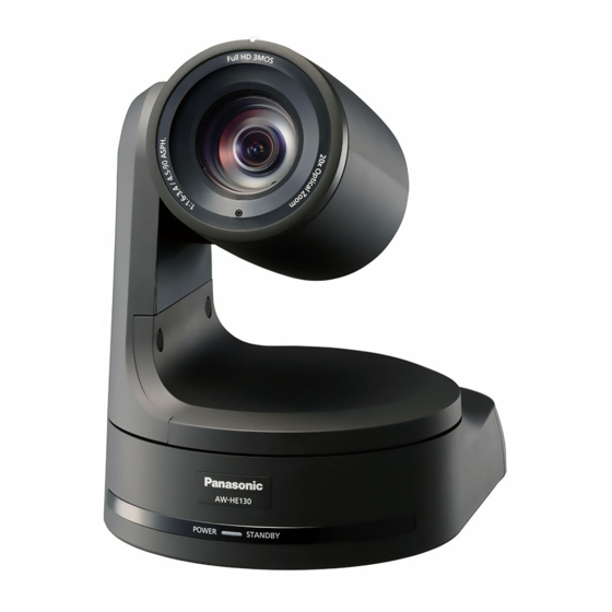
Windows 7 Professional SP1 64-bit ® ® • The unit supports standard serial communication formats, allowing / 32-bit connection to commercially available controllers. Windows Internet Explorer 11.0 / 10.0 / 9.0 ® ® / 8.0 • Connection with a Panasonic camera controller is also possible via For Mac: Panasonic's proprietary serial communication format. Mac OS 10.9 Safari 7.0.2 • The unit is available in white (AW-HE130W) or black (AW-HE130K) to suit your intended application and environment. Mac OS 10.8 Safari 6.1.2 Mac OS 10.7 Safari 6.1.2 For iPhone, iPad, iPod touch: iOS 7.1 Standard browser For Android: Android OS Standard browser Other CD-ROM drive (for using the Operating Instructions and various software) Adobe Reader ®... -
Page 11: Disclaimer Of Warranty
7, see “Notes on Windows ® 7” (→page @@). It is your responsibility to take precautions, such as those described • Depending on the software version of the unit, an update may be below, to protect yourself against the above network security risks. necessary. • Use the desktop version of Internet Explorer. (Internet Explorer for • Use the unit in a network secured by a firewall, etc. Windows UI is not supported.) • If the unit is connected to a network that includes personal computers, • For the latest information on compatible operating systems and web make sure that the system is not infected by computer viruses or other browsers, visit the support desk at the following website. malicious programs (using a regularly updated antivirus program, anti- http://pro-av.panasonic.net/ spyware program, etc.). • Protect your network against unauthorized access by restricting users to those who log in with an authorized user name and password. Disclaimer of warranty • Restrict access to the unit by authenticating the users, for example, IN NO EVENT SHALL Panasonic Corporation BE LIABLE TO ANY to prevent setting information stored on the unit from leaking over the PARTY OR ANY PERSON, EXCEPT FOR REPLACEMENT OR network. REASONABLE MAINTENANCE OF THE PRODUCT, FOR THE • Do not install the unit in locations where the unit, cables, and other CASES, INCLUDING BUT NOT LIMITED TO BELOW: parts can be easily damaged or destroyed by persons with malicious intent. -
Page 12: Features
• If the AC adapter and a PoE+ power supply are connected simultaneously, the AC adapter will have priority. If the AC adapter is Standard serial communication support „ disconnected while both power supplies are connected, the unit will • Connect up to seven cameras to a commercially available restart automatically, and the image will be interrupted. controller via RS-232C interface. • Use a Category 5e cable or higher when using a PoE+ power supply. The maximum length of the cable between the power supply unit High degree of compatibility with Panasonic’s „ and the unit is 100 meters (328 ft). Using a cable that is lower than currently available controllers, enabling a Category 5e may result in reuced power supply capabilities. flexible system to be put together Power over Ethernet Plus. Referred to as "PoE+" in this manual. • A maximum of five units can be operated by serial control from For details on PoE+ devices for which operation has been verified, one of Panasonic’s currently available controllers (AW-RP120, consult your local dealer or Panasonic representative. -
Page 13: Controller Supported
Controller supported z AW-RP120 z AW-RP50 z AK-HRP200 • It may be necessary to upgrade the version of the controller in order to support the unit. Consult with your dealer. <NOTE> • The following operations can not be performed via the following controllers. Item AW-RP400 AW-CB400 AW-RP555 AW-RP655 Gain configuration... -
Page 14: Accessories
Accessories Check that the following accessories are present and accounted for. • After removing the product from its container, dispose of the power cable cap and packing materials in an appropriate manner. CD-ROM (1) Mount bracket for installation Main unit mounting screw Power cable (1.8 m) (1) surface (with flat washer, spring (Hanging / Desktop). (1) washer) M3×6 mm (1) • Operating Instruction • Easy IP Setup Software (EasyIPSetup.exe) Drop-prevention wire. (1) Bracket mounting screws Cable cover (1) AC adaptor (1) -
Page 15: Operating Precautions
Operating precautions Shoot under the proper lighting conditions. Concerning the HDMI interface standard „ „ To produce pictures with eye-pleasing colors, shoot under the This unit has been certified as HDMI-compatible, but on rare proper lighting conditions. occasions images may not be displayed depending on the HDMI The pictures may not appear with their proper colors when shooting device which has been connected to the unit. under fluorescent lights. Select the proper lighting as required. Color bars „ To ensure a stable performance in the long „ • Color bars are used to adjust the color phase, and the widths and positions of these bars may differ from other models. term • The setting for the Down CONV. Mode item when color bars are Using the unit for prolonged periods in locations where the displayed is fixed at “Squeeze”. -
Page 16: Camera Head
Turning the camera head by hand may cause the unit to malfunction. Use the unit in an environment with minimal „ moisture and dust. Avoid using the unit in an environment with high concentration of moisture or dust since these conditions will damage the internal parts. Disposal of the unit „ When the unit has reached the end of its service life and is to be disposed of, ask a qualified contractor to dispose of the unit properly in order to protect the environment. Information on software used with this product „ This product includes GNU General Public License (GPL) and GNU Lesser General Public License (LGPL) licensed software, and the customer is entitled to obtain, modify, or redistribute the source code for the software. This product included MIT Licensed software. This product included BSD Licensed software. For details on obtaining the source codes, visit the following website. http://panasonic.biz/sav/ However, do not contact Panasonic for questions regarding obtained source codes. -
Page 17: Wireless Remote Control (Optional Accessory)
Wireless remote control (optional accessory) This unit can be operated by remote control using a wireless Layout of wireless remote control signal light-sensing areas remote control (model number: AW-RM50G) purchased separately. Check out the following points before using the wireless remote <NOTE>... -
Page 18: Parts And Their Functions
Parts and their functions Camera unit Mount bracket for installation surface (supplied accessory) Mount this bracket onto the installation surface, and then attach the camera main unit to the bracket. Drop-prevention wire This wire is screwed down to the bottom panel of the camera main unit. Loop the circle part of the wire around the hook of the mount bracket. Hole for securing the camera pedestal This hole is provided in the bottom panel of the camera pedestal. Wireless remote control signal light-sensing area The light-sensing area is provided in three places, on the front panel of the camera pedestal and at the top of the rear panel. Status display lamp This lights in the following way depending on the status of the unit. Orange: When the standby status is established Green: When the power is on Red: When trouble has occurred in the unit Green and blinks twice:... - Page 19 — Camera See descriptions for SW1 to SW3 1080/50p 576/50i 1080/50i address setting 1080/25p (standard serial 1080/50i 576/50i 1080/50i communication) 1080/25PsF 720/50p 576/50i 720/50p Communication Panasonic Standard serial 576/50p(i) 576/50i ― format proprietary serial communication communication <NOTE> Always leave at OFF (used for factory adjustments) • Locking to a subcarrier is not possible with BBS. Infrared output Disable Enable Communication 9600 bps 38400 bps VIDEO OUT connector <VIDEO OUT>...
- Page 20 1080/25psF 1080/23.98psF SW4 (communication format selection switch) 1080/29.97p Selects the communication format. When this is set to ON, standard serial communication is enabled. 1080/25p When this is set to OFF, Panasonic's proprietary serial 1080/23.98p communication is enabled. 720/59.94p 720/50p SW5 (maintenance switch) SD/SDI 480/59.94p Fixed at OFF.
-
Page 21: Wireless Remote Control (Not Supplied)
Parts and their functions (continued) Wireless remote control (not supplied) MODE button <MODE> This is used to select the video signals which are output from the unit. Each time it is pressed, the signals are switched between the color bar signals and camera video signals. <NOTE> • The setting for the Down CONV. Mode item when color bars are displayed is fixed at “Squeeze”. GAIN button <OFF> <LOW> <HI> <AUTO> These are used to set the gain. The gain increase can be set in three steps using the <OFF>, <LOW> and <HI> buttons. <LOW> is set to 9 dB, and <HI> is set to 18 dB. When the <AUTO> button is pressed, the AGC function is activated, and the gain is adjusted automatically depending on the light quantity. The maximum gain of the AGC function can be set using the camera menu. Preset memory call buttons <1> to <12> These are used to call the information on the unit’s directions and other settings, which have been registered in the unit’s preset memories No.1 to No.12, and reproduce those settings. - Page 22 Parts and their functions (continued) FOCUS button <F> <N> These are used to adjust the lens focus manually when the manual setting is established for the lens focus. The focus is adjusted in the far using the [F] button and in the near using the [N] button. A/FOCUS button <A/FOCUS> This is used when automatically adjusting the lens focus. M/FOCUS button <M/FOCUS> This is used when manually adjusting the lens focus. The FOCUS buttons (<F> and <N>) are used when performing the actual adjustment. OPT button <ON> <OFF> Turns the ND filter ON/OFF. HOME button <HOME> When this is pressed for 2 seconds, the unit’s direction (panning or tilting) returns to the reference position. ZOOM button <T> <W> These are used to adjust the lens zoom. The zoom is adjusted in the wide-angle using the <W> button and in the telephoto using the [T] button. FAST button <FAST>...
-
Page 23: Setting The Remote Control Ids
Setting the remote control IDs The wireless remote control (optional accessory) is capable of operating up to four units. IDs are used to set which units are selected when the <CAM1>, <CAM2>, <CAM3> and <CAM4> buttons on the wireless remote control have been pressed. • When operating a multiple number of these units using wireless remote controls, set a different remote control ID for each control. • When using one unit, set the remote control ID to “CAM1” unless the setting needs to be changed. Setting procedure „ Operate the IR ID switch on the units rear panel, and select “CAM1”, “CAM2”, “CAM3” or “CAM4” as the remote control ID. (→page 19) The IR ID switch settings “CAM1” to “CAM4” correspond to the <CAM1> to <CAM4> buttons on the wireless remote control. (The factory setting is “CAM1”.) IR ID switches <CAM1> to <CAM4> buttons... -
Page 24: Network Settings
Network settings Start the Easy IP Setup Software. Installing the software Be absolutely sure to read through the “Readme.txt” on the CD-ROM Click the [Search] button. supplied with the unit first before attempting to install the software. Software provided on the CD-ROM „ z Easy IP Setup Software (EasyIPSetup.exe) This software establishes the unit’s network settings. For details, refer to the sections that follow. Use the Easy IP Setup Software to establish the unit’s settings The settings related to the unit’s network can be established using the Easy IP Setup Software supplied. -
Page 25: Basic Shooting Operations
Basic shooting operations Set the subject brightness to the appropriate level. Start shooting. (After shooting, turn off the power of all the units and Turn on the power of all the units and devices in the devices in the system.) system. -
Page 26: Selecting The Units
Selecting the units Up to four units can be operated using one wireless remote control. Up to five units can be operated using one controller. Select the unit (or units) to be operated from the wireless remote control or controller. Even when using only one unit, it must still be selected. When performing operations from a wireless remote control To select the unit using the wireless remote control, the IR ID switches on the unit’s back panel must be set. For details of the IR ID switch settings, refer to pages @@, page @@. Press the <CAM1>, <CAM2>, <CAM3>, or <CAM4> button. The unit’s status display lamp blinks green when a signal matched by the remote control ID has been received, and it blinks orange when a signal that is not matched by the remote control ID has been received. When performing operations from a controller When using a AW-RP50, AW-RP120, or AK-HRP200 Refer to the operating instructions for the controller. -
Page 27: Selecting The Shooting Modes (Scene Files)
Selecting the shooting modes (scene files) Press the <M> button. Types of shooting modes The [Camera] sub-menu is displayed on the monitor. One of four shooting modes (Scene1, Scene2, Scene3 or Scene4) — C a m e r a whichever one will best suit the shooting conditions — can be selected. The shooting modes are set by the user. S c e n e S c e n e 1 For details of the factory settings, refer to pages 61 to 63. B r i g h t n e s s Select the mode that satisfies the shooting conditions and suits your P i c t u r e preferences. -
Page 28: Shooting
Shooting When performing operations from a wireless When performing operations from a controller remote control Changing the camera’s direction „ Changing the camera’s direction Moving the camera toward the left or right (panning): „ T ilt the <PAN/TILT> lever toward L or R. Moving the camera toward the left or right (panning): Press the <b> or <a> button. -
Page 29: What To Do When Encountering Problems In The Basic Shooting Operations
What to do when encountering problems in the basic shooting operations When performing operations from a controller If the trouble is not resolved by taking the action suggested below, refer to “Troubleshooting” (→ page 114). The unit does not move. When performing operations from a wireless • Select the unit to be operated by following the procedure below. remote control When using a AW-RP50, AW-RP120, or AK-HRP200 Refer to the operating instructions for the controller. -
Page 30: Manual Shooting
Manual shooting Manually adjusting the focus Manually adjusting the shutter speed The lens focus can be adjusted manually. The shutter speed can be set using two methods. One is a method that specifies the time (where a time such as 1/250 sec. is designated), and When performing operations from a wireless the other is a method that specifies the frequency (where synchro scan, 60.15 Hz, etc. is designated). remote control When shooting a TV screen or PC monitor screen, the horizontal noise generated when the screen is shot can be minimized by adjusting the Press the <M/FOCUS> button to switch the focus to frequency to the screen frequency using synchro scan. manual adjustment. When performing operations from a wireless Press the <F>... -
Page 31: Preset Memories
Preset memories When performing operations from a wireless This unit enables up to 100 settings for the camera direction (panning and tilting), zoom, focus, iris, gain and white balance to be registered in remote control its preset memories, and called. However, the number of settings that can be registered and called Twelve settings (preset No.1 to No.12) can be registered and called depends on the type of wireless remote control or controller that is used using the wireless remote control. for operation. The <1> to <12> buttons correspond to the unit’s preset memories No.1 to No.12. • The focus and iris operating modes (manual and auto settings) are neither registered nor recalled. The current focus and iris values are Registering the settings in the preset memories „ registered. Display the picture to be shot on the monitor. • The focus and iris values can be recalled only when the manual Operate the pan, tilt or zoom buttons to determine the camera angle. -
Page 32: White Balance Adjustment
White balance adjustment Adjust the ratio between the three primary colors (RGB) to reproduce Automatic adjustment (AWB: AWB A or AWB B) white accurately. If the white balance is out of adjustment, not only will When performing operations from a wireless white be reproduced poorly, but the color tones of the screen as a whole will also be degraded. remote control • Perform adjustment when using the unit for the first time or when Shoot a white subject (such as a white wall or the unit has not been used for a prolonged period. -
Page 33: Auto Tracking White Adjustment (Atw)
White balance adjustment (continued) Press the <SET> button for 2 seconds. 3200K and 5600K presets The auto white balance adjustment (AWB) and auto black balance When “3200K” or “5600K” is selected for the white balance, the white adjustment (ABB) are performed, and the white balance setting is balance is set using a color temperature of 3200K (equivalent to halogen entered. light) or 5600K (equivalent to daylight), respectively. • When [On] has been selected as the “OSD Status” (→ page This function works when “3200K” or “5600K” is selected instead of 58) setting, the “AWB OK” message will appear at the center of “AWB A” or “AWB B” by following the steps for “Automatic adjustment” in the screen when the white balance adjustment is completed “White balance adjustment” (→ page 32). successfully. (From the controller, this operation can be performed only using the When the black balance adjustment is completed successfully, the menu displays. Refer to “Basic operations” (→ page 37).) “ABB OK” message appears at the center of the screen. When [VAR] is selected for the white balance, you can select a color temperature between 2000K to 15000K. AW B OK <NOTE> • The displayed [VAR] value does not guarantee an absolute value. Use the value as a reference. -
Page 34: Black Balance Adjustment
Black balance adjustment When performing operations from a controller Adjust the zero levels of the three primary colors (RGB) to reproduce black accurately. If the black balance is out of adjustment, not only will black be reproduced poorly, but the color tones of the screen as a whole When using a AW-RP50, AW-RP120, or AK-HRP200 will also be degraded. Refer to the operating instructions for the controller. Readjustment of the black balance is not required under normal circumstances but is necessary in the following situations. • Perform adjustment when using the unit for the first time or when the unit has not been used for a prolonged period. •... -
Page 35: Black Level (Master Pedestal) Adjustment
Black level (master pedestal) adjustment When performing operations from a controller The black level can be adjusted when using a multiple number of cameras including the unit. Ask your dealer to perform this adjustment. (Use an oscilloscope or waveform monitor for the adjustment.) When using a AW-RP50, AW-RP120, or AK-HRP200 Adjust the black level in accordance with the units and devices used. Refer to the operating instructions for the controller. When performing operations from a wireless remote control Press the <M/IRIS> button. Set the iris to the manual mode. Press the <IRIS –> button. The lens iris is stopped down. -
Page 36: Genlock Adjustment
Genlock adjustment The genlock adjustment is performed to achieve phase alignment by Press the <4> or <5> button to bring the cursor to applying external synchronization (genlock) when a multiple number of [Genlock], and press the <M> button. cameras will be used or when the unit will be used in combination with The [Genlock] sub-menu is displayed. other devices. G e n l o c k This unit supports BBS (Black Burst Sync) and tri-level sync external synchronization signals. H o r i z o n t a l P h a s e Ask your dealer to perform this adjustment. -
Page 37: Basic Operations
Basic operations Camera menus are displayed on the monitor when the unit’s settings are Only the steps taken using the wireless remote control will be to be selected. described here for the operations conducted to select and set The monitor is connected to the video signal output connector. the items. The basic camera menu operations involve displaying sub-menus from For details of the operations conducted using the controller, the Top Menu items, and selecting settings on the sub-menus. substitute “controller” for “wireless remote control” when Some sub-menus have menu items for performing more detailed reading the basic operations. - Page 38 Basic operations (continued) Operations for controllers that are not supported „ Camera menu operation Unsupported controller Selecting a camera to operate Displaying the Top Menu Selecting items Displaying sub-menus Returning to the previous menu Changing settings Canceling setting changes Exiting camera menu operations...
-
Page 39: When Performing The Operations Using The Wireless Remote Control
Basic operations (continued) When performing the operations using the wireless remote control Press the [CAM1], [CAM2], [CAM3] or [CAM4] button to select the unit which is to be operated. Press and hold the <MENU> button for about 2 seconds. The Top Menu is displayed. Press the <4>... -
Page 40: Operations On The Aw-Rp50 Remote Camera Controller
Basic operations (continued) Operations on the AW-RP50 Remote Camera Controller For operating the camera menus. POWER ALARM CAMERA CAMERA OSD: W hen this is pressed for 2 seconds, the selected camera menu is displayed, overlapping MENU PAGE EXIT GAIN/PED R/B GAIN R/B PED AWB/ABB SHUTTER the camera output image. When it is pressed for 2 seconds while a camera menu is displayed, the STORE DELETE DETAIL SCENE/MODE CAMERA SETUP SYSTEM... - Page 41 Basic operations (continued) Preset speed table setting (PRESET SPEED) Optical image stabilization settings (OIS) „ „ Press the <MENU> button on the AW-RP50. Press the <MENU> button on the AW-RP50. The <MENU> button lights, and the <PRESET MEMORY/MENU> The <MENU> button lights, and the <PRESET MEMORY/MENU> buttons become selectable. buttons become selectable. Press the <9 (SETUP)> button in the <PRESET MEMORY/ Press the <9 (SETUP)>...
-
Page 42: Operations On The Aw-Rp120 Remote Camera Controller
Basic operations (continued) Operations on the AW-RP120 Remote Camera Controller For operating the camera menus. CAMERA OSD: W hen this is pressed for 2 seconds, the selected camera menu is displayed, overlapping the camera output image. When it is pressed for 2 seconds while a camera menu is displayed, the menu is exited. F1: T urn to move the cursor up and down in the camera menu or to change setting values. Press to move to the next level of a menu item or to change a setting value at the lowest level. Selects a camera to be operated. Camera menu operation Color temperature setting (COLOR TEMP) „... - Page 43 Basic operations (continued) Freezing images during preset playback „ (FREEZE DURING) Press the <MENU> button on the AW-RP120. The <MENU> button lights. Press the FUNCTION menu <29> button. The button lights, and the [OPTION] menu appears on the LCD panel. Turn the <F1> dial to select [FREEZE DURING], then press the <F1> dial. [Off] or [On] appears on the bottom right (F2 area) of the LCD panel. Turn the <F2>...
-
Page 44: Operations On The Ak-Hrp200 Remote Operation Panel
Basic operations (continued) Operations on the AK-HRP200 Remote Operation Panel AUTO HEAD POWER POWER BARS WHITE BLACK SET UP TEST KNEE SHUTTER 5600K MATRIX SKINDTL STEP/SYNC SCENE/USER FILE SHIFT SCENE 1 SCENE 2 SCENE 3 SCENE 4 STORE USER 1 USER 2 USER 3 GAIN... - Page 45 Basic operations (continued) The following operations can be performed from the AK-HRP200 Remote Operation Panel. For details on operations, refer to the AK-HRP200 Operating Instructions <Basics>. Control/display component Label HE130 Remarks Camera power switch HEAD POWER Supported VF power switch VF POWER ― Supported with some Color bar signal output switch BARS/TEST Does not transition to TEST_ON. restrictions Running state after accepting AWB/ABB Auto white balance switch AUTO WHITE Supported lasts at least 2 sec. Running state after accepting AWB/ABB Auto black balance switch AUTO BLACK Supported lasts at least 2 sec. Auto setup switch AUTO SETUP ― 5600 k switch 5600k ― Matrix switch MATRIX ― Skin color detail switch SKIN DTL ON ―...
- Page 46 Basic operations (continued) Control/display component Label HE130 Remarks Only enabled during MENU ON. When ZOOM is selected, FOCUS adjustment is possible on the selection Rotary selection switch SELECT Supported dial. When FOCUS is selected, ZOOM adjustment is possible on the selection dial. Supported with some Red/green tally display, call switch TALLY/CALL CALL is disabled. restrictions Alarm display ALARM ― Optical alarm display ― Iris / master pedestal lock IRIS/M.PED LOCK Supported Supported with some The IRIS value cannot be displayed for Iris lever IRIS (↑↓) restrictions 7SEG. Master pedestal volume M.PED (← →) Supported Preview switch PUSH PREVIEW ―...
-
Page 47: Camera Menu Items
Camera menu items Setting the camera menu items Top Menu screen Camera menus are displayed on the monitor when the unit’s settings are T o p M e n u to be selected. The monitor is connected to the video signal output connector. C a m e r a S c e n e : S c e n e 1 The basic camera menu operations involve displaying sub-menus from S y s t e m the Top Menu items, and selecting settings on the sub-menus. -
Page 48: Camera Screen
Camera menu items (continued) Camera screen Brightness 1/2 screen This menu is used for the camera image settings. This menu item is selected to set the brightness of the pictures. Ca mer a B r i g h t n e s s 1 / 2 S cene Scene1 P i c t u r e L e v e l Brig htn e s s I r i s M o d e A u t o... -
Page 49: Brightness 2/2 Screen
Camera menu items (continued) [When 50 Hz has been set as the unit’s frequency] Brightness 2/2 screen When [Step] is selected as the When [Synchro] is selected as [Shutter Mode] the [Shutter Mode] B r i g h t n e s s 2 / 2 •... -
Page 50: Picture 1/3 Screen
Camera menu items (continued) Picture 1/3 screen Picture 2/3 screen P ict u r e 1 / 3 P i c t u r e 2 / 3 Chrom a L e v e l D e t a i l White Ba l a n c e M o d e A W B A M a s t e r D e t a i l... -
Page 51: Picture 3/3 Screen
Camera menu items (continued) Picture 3/3 screen Matrix 1/5 screen P i c t u r e 3 / 3 M a t r i x 1 / 5 Kne e M o d e A u t o M a t r i x T y p e N o r m a l Kn e e P o i n t 9 3 . -
Page 52: Matrix 2/5 Screen
Camera menu items (continued) Matrix 2/5 screen Matrix 3/5 screen M atr i x 2 / 5 M a t r i x 3 / 5 [ L i n e a r M a t r i x ] [ C o l o r C o r r e c t i o n 1 / 3 ] S a t u r a t i o n P h a s e... -
Page 53: Matrix 4/5 Screen
Camera menu items (continued) Matrix 4/5 screen Matrix 5/5 screen M a t r i x 4 / 5 M a t r i x 5 / 5 [ C o l o r C o r r e c t i o n 2 / 3 ] [ C o l o r C o r r e c t i o n 3 / 3 ] S a t u r a t i o n P h a s e... -
Page 54: System Screen
Camera menu items (continued) System screen Genlock screen This menu has items that relate to the genlock phase adjustment and G e n l o c k camera’s output image settings. Sy ste m H o r i z o n t a l P h a s e H o r i z o n t a l P h a s e S t e p Genlo ck Outpu t Other s... -
Page 55: Output Screen
Camera menu items (continued) Frequency [59.94Hz, 50Hz] Output screen This item is selected to switch the frame frequency. • When the frequency is switched, [Format] is set as follows. O u t p u t 59.94Hz 50Hz For m a t 1 0 8 0 / 5 9 . 9 4 i 1080/59.94p 1080/50p Dow n C O N V . M o d e S q u e e z e 1080/29.97p 1080/25p... - Page 56 Camera menu items (continued) Changing the format Changing the frequency „ „ When the currently selected format is changed in the [Output] screen, When the currently selected frequency is changed in the [Output] the pre-format-change confirmation screen appears. screen, the pre-frequency-change confirmation screen appears. Pre-format-change confirmation screen Pre-frequency-change confirmation screen F orm a t F r e q u e n c y Do yo u w a n t t o s e t D o y o u w a n t t o s e t Forma t(1 0 8 0 / 5 9 .
-
Page 57: Other 1/4 Screen
Camera menu items (continued) Other 1/4 screen Other 2/4 screen O t h e r s 1 / 4 O t h e r s 2 / 4 Ins t a l l P o s i t i o n D e s k t o p F o c u s M o d e A u t o... -
Page 58: Other 3/4 Screen
Camera menu items (continued) Other 3/4 screen Other 4/4 screen O the r s 3 / 4 O t h e r s 4 / 4 Wirel ess C o n t r o l E n a b l e A u d i o O f f OSD M ix... -
Page 59: Maintenance Screen
Camera menu items (continued) Maintenance screen Firmware VER 1/2 screen M a i n tena nce F i r m w a r e V E R 1 / 2 Fi rm w a r e Ve rsion C P U S o f t w a r e IP N e t w ork I n t e r f a c e V 0 1 . -
Page 60: Ip Network Screen
Camera menu items (continued) Menu settings initialized screen IP Network screen I P N e t w o r k IP Ad dre s s M e n u s e t t i n g s 1 9 2 . 1 6 8 . 0 . -
Page 61: Camera Menu Items
Camera menu items Camera menu Item Factory setting Selection items Top Menu Camera Scene Scene Scene1 Scene1, Scene2, Scene3, Scene4 -50 to +50 (step: 1) Brightness Brightness Picture Level Iris Mode Auto Manual, Auto Shutter Mode Off, Step, Synchro, ELC Step/Synchro [59.94Hz] [When Frequency is set to 59.94 Hz] (When [Shutter Mode] 1/100 • 59.94p / 59.94i mode is set to [Step]) [50Hz] 1/100, 1/120, 1/250, 1/500, 1/1000, 1/2000, 1/120 1/4000, 1/10000 • 29.97p mode 1/30, 1/60, 1/120, 1/250,1/500, 1/1000, 1/2000, 1/4000, 1/10000 • 23.98p mode... - Page 62 Camera menu items (continued) Camera menu Item Factory setting Selection items Top Menu Camera Scene Matrix Matrix 1/5 Matrix Type Normal Normal, EBU, NTSC, User Matrix 2/5 [Linear Matrix] Normal EBU NTSC User -63 to +63 -63 to +63 -63 to +63 -63 to +63 -63 to +63 -63 to +63 Matrix 3/5 [Color Correction 1/3] Normal EBU NTSC User B_Mg Saturation -63 to +63 B_Mg Phase -63 to +63 Mg Saturation -63 to +63...
- Page 63 Camera menu items (continued) Camera menu Item Factory setting Selection items Top Menu System Others Others 1/4 Install Position Desktop Desktop, Hanging Smart Picture Flip Off, Auto Flip Detect Angle 90deg 60 to 120deg (step: 1deg) Preset Speed Table Fast Slow, Fast Preset Speed 1 to 30 Preset Scope Mode A Mode A, Mode B, Mode C Freeze During Preset Off, On Speed With Zoom POS. On Off, On Others 2/4 Focus Mode Auto Manual, Auto Focus ADJ With PTZ.
-
Page 64: Displaying The Web Screen
Displaying the web screen With a personal computer connected to the unit, it is possible to view Displaying the web screen using a personal the camera’s IP videos or select various settings from the web browser computer screen. The procedure is explained here using Windows screens (Internet The LAN crossover cable is used when connecting a personal computer Explorer), but it is the same when using the Mac (Safari) screens. directly to the unit’s LAN connector for IP control, and the LAN straight There may be differences in some parts of the screen displays. cable is used when making the connection through a switching hub. Start the web browser of the personal computer. Select an IP address for the personal computer within the private Use one of the web browsers below depending on the operating address range while ensuring that it is different from the address of the system installed in the personal computer. unit. Set the subnet mask to the same address as the unit. Operating system Web browser installed <NOTE>... -
Page 65: Switching Between The Live Screen And Setup Screen
Displaying the web screen (continued) <NOTE> Switching between the Live screen and Setup • If the personal computer does not have the plug-in viewer software screen already installed, an installation confirmation message is displayed before the Live screen is displayed. In a case like this, follow the When the Live screen is displayed, click the button. on-screen instructions to install the software. For details on the Setup screen, see “Setup screen” (→ page @@). For further details, refer to “Plug-in viewer software (Network Camera View 4S)” (→ page @@). • When “User Authentication” (→ page @@) is set to “On”, the user name and password input screen is displayed before the Live screen page appears. The default settings for the user name and password are as follows. User name admin Password 12345 • While the initial settings remain used for the user name and password, a message prompting the user to change the user name When the Setup screen is displayed, click the button. and password is displayed after authorization. In order to ensure For details on the Live screen, see “Live screen” (→ page @@). -
Page 66: Web Screen Operations
Web screen operations The Live screen includes a “single display mode” that displays IP images from a single camera and a “multi display mode” that displays IP images from multiple cameras. See below for details on the single display mode, and see page @@ for details on the multi display mode. Live screen: Single display mode You can display images from the camera on a computer and perform camera operations, such as pan, tilt, zoom, and focus control. The items displayed on the screen will differ depending on whether the [H.264] or [JPEG] button is selected under [Compression]. When [H.264] is selected When [JPEG] is selected... - Page 67 Web screen operations (continued) Multi-Screen list box (Multi-screen) Image Capture Size buttons The Live screen display method is selected here. These buttons appear only when JPEG images are displayed. When selected, the text on the button turns The IP videos of the connected camera are green, and the images in the main area appear displayed. (Single) (1920 x 1080) in 1920 x 1080 size. When selected, the text on the button turns (1280 x 720) green, and the images in the main area appear (4Split 1/4 Group) in 1280 x 720 size. When selected, the text on the button turns green, and the images in the main area appear (4Split 2/4 Group) (640 x 360) in 640 x 360 size. When the cameras for multi-screen display have been set ahead of time using the multi- When selected, the text on the button turns screen (→page @@), it is possible to view green, and the images in the main area appear (4Split 3/4 Group) a multiple number of IP videos on a single (320 x 180) in 320 x 180 size. screen. (Multi display mode) When selected, the text on the button turns (160x90)
- Page 68 Web screen operations (continued) Power ON button / <NOTE> • When the shooting scenes vary significantly, restrictions imposed Standby button by the graphics processing (GDI) of the operating system installed may give rise to a phenomenon called “screen tearing” (where parts Turn the unit on. of the picture are not displayed in synchronization) although this will (Power ON) depend on the personal computer used. • On a personal computer running Windows, if “H.264 transmission” Set the unit to STANDBY mode. (→page @@) is set to “On”, H.264 images and JPEG images can (Standby) be displayed. H.264 images will appear immediately after they appear on the Live screen (in single display mode). When it is set to In the standby mode, all the buttons on the Live screen except for the [Off], only JPEG images will appear. [Multi-screen] list box, [Power ON] button, [Standby] button and [Op. • On a personal computer running Mac OS X, regardless of the Lock] button are disabled. “H.264 transmission” settings, only JPEG images will appear. <NOTE> (H.264 images will not appear.) • If Power ON or Standby is selected too quickly, the status selected • When [H.264 transmission] is set to [On], the frame rate for JPEG and the display shown may not correspond. In a case like this, images may drop, regardless of whether H.264 images are being follow the steps below to restore the correct status display: transmitted.
-
Page 69: Snapshot Button
Web screen operations (continued) Control pad and its buttons Full-screen display button To adjust the image in the horizontal or vertical Display the image in full-screen mode. direction (panning or tilting), left-click the pad and When the image displayed in the main area is the buttons. compressed, clicking this once displays the image at the The more the outside of the pad is clicked, the correct resolution in the main area. When the image is faster the camera operates. Adjustment is also displayed at the correct resolution, the image is displayed possible by dragging the mouse. in full-screen mode. To return to the live image page, Right-click the pad to initiate zooming and press the [Esc] key on the computer while the image is focusing. displayed in full-screen mode. When the top half of the pad is clicked in the up The aspect ratio of the displayed image will be adjusted or down direction, the zoom (magnification) is according to the monitor size. adjusted in the Tele direction; conversely, when the bottom half of the pad is clicked, the zoom is adjusted in the Wide direction. Snapshot button When the left half of the pad is clicked in the left or right direction, the focus is adjusted in the Near Capture a snapshot (single still image), and display it in a direction; conversely when the right half of the separate window. A menu appears when you right-click the image, and you can select [Save] to save the image to the... -
Page 70: Live Screen: Multi Display Mode
Web screen operations (continued) Live screen: Multi display mode In this mode, the images of a multiple number of cameras can be monitored on one screen (called the ‘multi screen’). The image of 4 cameras or max. 16 cameras can be monitored at one time. When the camera title of any of the images is clicked, the Live screen (single display mode) of the camera concerned is displayed as a separate window. In order to use the multi screen, the cameras whose images are to be shown on the multi screen must be set ahead of time. With one group consisting of 4 cameras, up to four groups of cameras (a total of 16 cameras) can be registered. (→page @@) Multi screen consisting of 4 sub-screens Multi screen consisting of 16 sub-screens Multi-Screen list box (Multi-screen) <NOTE> • The IP videos displayed on the multi screen are JPEG images only. The Live screen display method is selected here. • IP images are in JPEG format only and audio is not output. The IP videos of the connected camera are • Images are stretched vertically to fit the [4:3] aspect ratio of the multi displayed. -
Page 71: Web Screen Configurations
Web screen configurations Logging into the Setup screen Click the [Setup] button. (→ page @@) Click the [OK] button. The login screen appears. Click [OK] again when the following screen appears. <NOTE> • While the initial settings remain used for the user name and password, a message prompting the user to change the user name Enter the user name and password. and password is displayed after authorization. In order to ensure The default settings for the user name and password are as follows. security, the password for the user name of “admin” must be User name admin changed without fail. Password 12345 It is also recommended that the password be changed at regular intervals. -
Page 72: Basic Screen
Web screen configurations (continued) Power ON button / Standby button Basic screen Turn the unit on. (Power ON) Set the unit to STANDBY mode. (Standby) In the standby mode, it is not possible to select [Image/Position] or [System] under the Image button or [Backup] under the Maintenance button. All items in the [Setup] screen are also disabled. Camera title Main area Input the name of the camera here. When the Set button is clicked, the input name appears in the camera The menu screen is displayed. title display area. • The initial setting is “AW-HE130.” Camera title display area. • You can enter between 0 to 20 half-size characters. The name for the unit configured in the Basic screen (→ page @@) • The following characters can be displayed. appears. Half-size numeric 0123456789 characters Half-size... -
Page 73: Image Screen
Web screen configurations (continued) Refresh interval (JPEG) Image screen Select the frame rate for JPEG images. IP video settings tab (Video over IP) Setting value: „ For 60Hz: The JPEG image and H.264 image settings as well as the settings 1fps/2fps/3fps/5fps/6fps /10fps /15fps /30fps related to image quality are selected on this screen. For 50Hz: 1fps/2fps/5fps/10fps /12.5fps /25fps Factory settings: 5fps When [H.264 transmission] is set to [On], the frame rate may be slower than the specified value in some cases. <NOTE> • The frame rate may be slower depending on the network environment, resolution, image quality, access volume, etc. - Page 74 Web screen configurations (continued) Internet mode (over HTTP) Framerate This setting is selected when transmitting H.264 images over the Set the frame rate for H.264 images. Internet. Setting value: H.264 images can be transmitted using the same broadband router For 60Hz: settings as when transmitting JPEG images. 5fps / 15fps / 30fps / 60fps Setting value: For 50Hz: 5fps / 12.5fps / 25fps / 50fps The H.264 images and audio are transmitted using the HTTP Factory settings: port. For details on setting the HTTP port number, refer to For 60Hz: 30fps page @@. For 50Hz: 25fps The H.264 images and audio are transmitted using the UDP port.
- Page 75 Web screen configurations (continued) Max bit rate (per client) Transmission type Specify the H.264 bit rate per client. Select the transmission format for H.264 images. When [Transmission priority] is set to [Best effort], specify the Setting value: maximum and minimum but rate. Unicast port Up to 24 users can access a single camera at the Setting value: (AUTO) same time. 64kbps/128kbps /256kbps /384kbps /512kbps [Unicast port1 (Image)] and [Unicast port2 768kbps /1024kbps /1536kbps /2048kbps /3072kbps (Audio)] will be configured automatically when 4096kbps /6144kbps /8192kbps /10240kbps images and audio are sent from the camera. We recommend selecting the [Unicast port 12288kbps /14336kbps /16384kbps...
- Page 76 Web screen configurations (continued) Audio Multicast address „ Enter the multicast IP address. Configure audio settings. Images and audio will be sent to the specified IP address. <NOTE> Usable values: • Images and audio are not synchronized. Therefore, there may images IPv4: 224.0.0.0 to 239.255.255.255 and audio may be slightly out of sync. IPv6: Multicast address starting with FF. • The audio may skip depending on the network environment. Factory settings: H.264(1): 239.192.0.20 H.264(2): 239.192.0.21 H.264(3): 239.192.0.22 H.264(4): 239.192.0.23 <NOTE> • Verify usable multicast IP addresses before entering this setting. Multicast port Enter the multicast port number (used when sending images from the unit). Usable port number range: 1024 to 50000 • Only even numbers can be specified. Audio reception • The port number cannot be set to 10670.
-
Page 77: Preset Position
Web screen configurations (continued) Image / Position screen z Image adjust screen „ Adjust the image quality. Display the image quality adjustment / preset position screen. To display the Image adjust screen, click the Setup button for [Image adjust] at the bottom of the Image/Position screen. Scene Switch the shooting mode depending on the shooting environment. Select a shooting mode based on the shooting conditions or preference. Select a shooting mode from the pull-down menu, and click the Set button to switch to the selected mode. Setting value: Scene1 Modes that allow you to adjust detailed settings manually Scene2 for various shooting conditions and preferences. Scene3 Scene4 Image adjust When you click the Setup button, the image quality adjustment screen Brightness appears. (→page @@) Preset position When you click the Setup button, the preset position screen appears. (→page @@) Picture Level Set the target picture level for auto exposure correction. - Page 78 Web screen configurations (continued) Shutter Mode Frame Mix Select for camera shutter speed. Select for frame addition (gain-up using sensor storage) amount. When a higher shutter speed is selected, fast-moving subjects do not When frame addition is performed, it will appear as if the images are become blurred easily but the images will be darker. missing some frames. Setting value: Setting value: The shutter is set to OFF. Frame addition is not performed. Step The step shutter is set (the steps can be changed). Set the frame addition amount to 6 dB. Synchro The synchro shutter is set (the setting can be changed 12dB Set the frame addition amount to 12 dB. continuously). 18dB Set the frame addition amount to 18 dB. The electronic shutter is controlled and the light quantity 24dB Set the frame addition amount to 24 dB. is adjusted automatically. • This cannot be configured when the format is 1080/29.97p, The shutter speeds that can be set are listed below. 1080/23.98p, 1080/29.97PsF, 1080/23.98PsF, 1080/25p, or 1080/25PsF. When 59.94 Hz has been set as the unit’s frequency • The auto exposure correction and auto focus functions will be When “Step”...
- Page 79 Web screen configurations (continued) Picture Chroma Level Set here is the color intensity (chroma level) of the images. Setting range: OFF, -99% to 40% White Balance Mode Set the white balance mode. Select the mode when the coloring is not natural because of the nature of the light source or other factors. If the white color serving as the reference can be recognized, subjects can be shot with natural coloring. Setting value: In this mode, the white balance is compensated for automatically, even if changes occur in the light source or color temperature, by a process of continuous and automatic adjustment. AWB A When AWB A or AWB B is selected and the white balance is AWB B executed, the adjustment results obtained are stored in the memory selected. When AWB A or AWB B is then selected, the white balance stored in the selected memory can be recalled. 3200K This is the white balance mode which is ideal when a 3200K halogen light is used as the light source. 5600K This is the white balance mode which is ideal when 5600K sunlight or fluorescent lighting is used as the light source. Specify a color temperature between 2000K and 15000K. This is used to execute automatic white balance (AWB) to set the white balance. For further details, refer to page @@.
- Page 80 Web screen configurations (continued) Pedestal Gamma This item is used to adjust the black level (adjust the pedestal). Adjust the gamma correction level. These parts become darker when a negative setting is selected and, Specifying a lower value results in a subdued image. The gamma conversely, lighter when a positive setting is selected. curve for low-brightness areas will be gentler, and contrast will be Setting range: -150 to +150 sharper. Specifying larger values results in an expanded gradient for dark R Pedestal areas and produces brighter images. The gamma curve for low- This enables the R pedestal to be adjusted. brightness areas will be steeper, and contrast will be softer. The same R pedestal setting is used for all the scenes. Setting range: 0.30 to 0.75 Setting range: -100 to +100 B Pedestal Set the DRS function which performs correction when video with high This enables the B pedestal to be adjusted. light/dark contrast is displayed. The same B pedestal setting is used for all the scenes. You can select from a [Low], [Mid], or [High] effect level. Setting range: -100 to +100 Depending on the scene, noise may worsen. Setting value: Detail Turn the DRS function off.
-
Page 81: Color Correction
Web screen configurations (continued) z Matrix Settings screen Matrix Type Set matrix settings. Select the type of color matrix. To display the Matrix Settings screen, click the Setup button for [Matrix Setting value: Type] at the bottom of the Image/Position screen. Normal Load preset color matrix data, and perform saturation and hue adjustment. NTSC User Adjust the [Linear Matrix] and [Color Correction] values. Linear Matrix This is enabled when the matrix type is set to [User]. Setting value: Adjust the color to between –63 to +63 for each axis direction. Color Correction Adjust the saturation and hue. Saturation Adjust the saturation for each color. Setting range: -63 to +63 Phase Adjust the hue for each color. Setting range: -63 to +63 B_Mg Color between blue and magenta Magenta... - Page 82 Web screen configurations (continued) z Preset position screen Zoom Adjust the image quality. Use this to adjust the zoom (magnification) in the Wide To display the Image adjust screen, click the Setup button for [Preset direction. position] at the bottom of the Image/Position screen. Use this to adjust the zoom (magnification) to 1.0x. (×1.0) Use this to adjust the zoom (magnification) in the Tele direction. Use this to enable or disable the digital zoom. (D. Zoom) Enable or disable the digital extender. This operates only when digital zoom is disabled. (D. Ext) Focus Use this to adjust the focus in the Near direction. It does not work during automatic adjustments. (Near) When this is pressed while the focus is being adjusted manually, the focus will be temporarily adjusted automatically. It does not work during automatic (O.T. AF) adjustments. Use this to adjust the focus in the Far direction. It does not work during automatic adjustments. (Far) Use this to switch between auto and manual focusing. (Auto) Brightness Use this to make the image darker. It does not work during automatic adjustments. Use this to make the image lighter.
- Page 83 Web screen configurations (continued) Speed With Zoom POS. Limitation Setting “Off” or “On” is set here for the function used to adjust the pan-tilt This establishes the up, down, left and right limit settings of the pan- adjustment speed in conjunction with the zoom magnification. tilt head. Setting value: First, move the pan-tilt head to the position where the limit is to be set, and press the corresponding button below to set the direction (up, The panning and tilting operations will not become slower in the down, left or right) in which the limit is to be set. zoom status. After each setting has been selected, press the Set button to enter The panning and tilting operations will become slower in the the setting. zoom status. This function has no effect during preset operations. Use this to save the current position as the upward Tilt Up limit. Use this to save the current position as the downward Focus ADJ With PTZ. Tilt Down limit. “Off” or “On” is set here for the function which compensates for out-of- Use this to save the current position as the leftward focusing when it occurs during panning, tilting or zooming operations. Pan Left limit.
- Page 84 Web screen configurations (continued) System screen z Output „ This item’s setting is reflected when the Set button is pressed. This menu has items that relate to the genlock phase adjustment and camera’s output image settings. Format The video format is changed on this screen. For 480/59.94p(i) and 576/50p(i), P signals are output for HDMI, while I signals are output for SDI and analog component outputs. Setting value: For 59.94Hz: 1080/59.94p, 1080/29.97p, 1080/23.98p, 1080/59.94i, 1080/29.97PsF, 1080/23.98PsF, 720/59.94p, 480/59.94p(i) For 50Hz: 1080/50p, 1080/25p, 1080/50i, 180/25PsF, 720/50p, 576/50p(i) <NOTE> • When you switch from an HD format to an SD format or vice versa, the unit automatically restarts after the Format Set screen appears. Down CONV. Mode The down-conversion mode is selected here. Setting value: Use this when the aspect ratio of the monitor is 16:9. When the 4:3 aspect ratio has been set for the monitor screen, the images are squeezed horizontally and extended vertically changing the view of the angle. Squeeze Use this when the aspect ratio of the monitor is 4:3. With the vertical height serving as the reference, the parts which extend beyond this at the two sides are cropped...
- Page 85 Web screen configurations (continued) Frequency Preset Scope This item is selected to switch the frame frequency. Selected here are the setting items to be recalled when the contents Setting value: of the preset memory are regenerated. 59.94Hz / 50Hz Setting value: • When the frequency is switched, “Format” is set as follows. Pan, Tilt, Zoom (including digital zoom), Focus, Iris, Gain, Mode A white balance adjustment value 59.94Hz 50Hz Mode B Pan, Tilt, Zoom (including digital zoom), Focus, Iris 1080/59.94p 1080/50p Mode C Pan, Tilt, Zoom (including digital zoom), Focus 1080/29.97p 1080/25p 1080/23.98p 1080/25p 1080/59.94i 1080/50i Freeze During Preset 1080/29.97PsF 1080/25PsF Turn the function for freezing images during preset playback off/on.
-
Page 86: Multi-Screen Setup Screen
Web screen configurations (continued) Digital Extender Multi-Screen setup screen Enable or disable the digital extender. The cameras whose images are to be displayed on the multi screen are When this is set to [On], the digital zoom will be fixed at 1.4x. set here. (→page@@, page @@) When [Digital Zoom] is set to [Enable], [Digital Extender] is disabled. Setting value: Disable the digital extender function. Enable the digital extender function. Tally “Enable” or “Disable” is set here for the function which turns on or turns off the tally lamp using the tally control signal. Setting value: Disable Disable the tally lamp function. Enable Enable the tally lamp function. Tally Brightness Adjust the brightness of the tally LED. Setting value: Low brightness Medium brightness High High brightness <NOTE> • When this is set to [Low], the LED brightness is equivalent to that of the AW-HE120. OSD Mix Select whether to turn off/on camera menu, status, and other displays for each output image. -
Page 87: User Mng. Screen
Web screen configurations (continued) Camera title User mng. screen Input the camera title here. The camera title which has been input is The users and computers (IP addresses) that can access the unit from displayed on the multi screen. computers and mobile terminals are registered in the User mng. screen. Maximum 0 to 20 half-size characters The User mng. screen consists of three tabs, “User auth.”, “Host auth.” number of and “Priority Stream”. characters Invalid Symbols User auth. screen „ characters Click the User auth. tab of User mng. screen. (→page @@, page @@) Factory settings: Configure the user authorization settings for the computers and mobile Cam 1: The product number appears. terminals that can access the unit. Cam 2 to Cam 16: blank Up to 24 users can be registered. <NOTE> <NOTE> • When a 16-screen multi screen is selected, camera titles may be • If user authentication fails more than 8 times within a 30-second only partially displayed. - Page 88 Web screen configurations (continued) Host auth. screen Password / Retype password „ Input the password. Click the Host auth. tab of User mng. screen. (→page@@, page @@) Configure the host authorization settings that restrict the computers (IP Maximum 4 to 32 half-size characters addresses) that can access the unit. number of characters Invalid " & characters Factory settings: blank <NOTE> • If you enter a new name for a registered user and click the Set button, the user information will be overwritten. Access level Select one of the following settings as the user access level. Setting value: This access level allows the user to perform all 1. Administrator the unit’s operations. Host auth. [On, Off] This access level allows only Live screen Host authorization is set to “On” or “Off” here.
-
Page 89: Network Setup Screen
Web screen configurations (continued) Priority stream screen „ Network setup screen Click the Priority stream tab of User mng. screen. (→page@@, page Configure network settings in the Network setup screen. The Network setup screen consists of the two tabs of “Network” and Selected on this screen are the settings for the priority stream which “Advanced”. enables the images to be sent with no reduction in image quality or image refresh speed even when a multiple number of users are Network setup screen „ accessing the unit at the same time. Click the “Network” tab of the Network setup screen. (→page@@, page z Priority Stream Activation [On, Off] Whether to use priority stream transmission is set here using “On” or “Off”. Setting value: Use priority stream transmission. Do not use priority stream transmission. Factory settings: Off <NOTE> • When [Activation] is set to [On], the number of users that can access the unit may be restricted. - Page 90 Web screen configurations (continued) z IPv4 network z IPv6 network Network Settings Manual Select the method in which the IP address is configured. Enable or disable manual configuration of the IPv6 address. Setting value: Setting value: Enter the IP address in the [IP address(IPv4)] Enter the IPv6 address manually. Static field. Disable manual entry of the IPv6 address. Use the DHCP function to configure the IP DHCP Factory settings: Off address. Use the DHCP function to configure the IP IP address (IPv6) Auto(AutoIP) address. If the DHCP server cannot be found, When [Manual] is set to [On], the IPv6 address must be entered the IP address will be configured automatically. manually. Use the DHCP function to browse network Be sure to enter an address unique from other devices.
- Page 91 Web screen configurations (continued) Max RTP packet size Easy IP Setup accommodate period Specify whether to limit the size of RTP packets sent from the camera Select “20min” or “Unlimited” as the time for enabling the operation of when using RTP to view camera images. the network settings from the Easy IP Setup Software. Setting value: Setting value: Unlimited (1500byte) Unlimited (1500byte) The setting operations from the Easy IP Setup 20min Software are enabled for 20 minutes after the Limited (1280byte) Limited (1280byte) camera has started operating. Factory settings: Unlimited (1500byte) The setting operations from the Easy IP Setup Unlimited Software are enabled at all times. Normally, it is recommended that the “Unlimited(1500byte)” setting be Factory settings: 20min used. <NOTE>...
- Page 92 Web screen configurations (continued) Advanced network setting screen Recommended network setting for internet „ Perform the recommended settings to connect the camera to the Click the “Advanced” tab in the network setting screen (→page@@, Internet. page @@) Clicking the “Set” button displays a dialog box telling the user that Settings relating to the NTP, UPnP, HTTPS, SNMP, and Diffserv item settings will be changed. After confirming this, click the “OK” functions are performed here. button. Click the links to each item to move to the respective setting page. • Camera image’s “JPEG/H.264” tab z NTP JPEG(1) Settings relating to the NTP server address and port No. are Image capture size: 640×360 performed here. JPEG(2) Image capture size: 320×180 JPEG(3) Image capture size: 160×90 H.264(1) • H.264(2) • H.264(3) • H.264(4) Internet mode (over HTTP): On Transmission priority: Best effort H.264(1)
- Page 93 Web screen configurations (continued) Time adjustment interval Camera short cut Selects the interval (1 to 24 hours in 1-hour increments) for acquiring Whether to create a camera short cut in the “Network” folder of your the time from the NTP server. personal computer is set by selecting “On” or “Off”. Setting range: 1h to 24h Select “On” to create a camera short cut. Factory settings: 1h To use the camera short cut function, enable the UPnP function in advance in your personal computer. Setting value: Time zone Selects the time zone according to the region where the camera is Creates a camera short cut in the "Network" folder of your being used. personal computer. Factory settings: No camera short cut is created in the "Network" folder of (GMT)Greenwich Mean Time: Dubin,Edinburgh, Lisbon, London your personal computer. Factory settings: Off Summer time(daylight saving) [In, Out, Auto] <NOTE>...
- Page 94 Web screen configurations (continued) CA Certificate - Generate Certificate Signing Request HTTPS port[1 to 65535] When using a security certificate issued by the Certificate Authority This sets the Port No. to be used with HTTPS. (CA) as a security certificate for HTTPS, a Certificate Signing Request Port Nos. that can be selected 1 to 65535 (CSR) is generated for application to the Certificate Authority (CA). The following port numbers are used by the unit so they cannot be To generate a Certificate Signing Request (CSR), click the “Execute” used. button to display the “Certificate Signing Request (CSR) Generate” 20, 21, 23, 25, 42, 53, 67, 68, 69, 80, 110, 123, 161, 162, 554, 995, dialog and perform the operation. 10669, 10670, 59000 to 61000 For more details, refer to “Generating a Certificate Signing Request Factory settings: 443 (CSR)” (→ page@@) <NOTE> • This unit will restart if the connection method is changed.
- Page 95 Web screen configurations (continued) Contact Input the email address or telephone number of the administrator. Maximum number 0 to 255 half-size characters of characters Invalid characters Full size characters Factory settings: blank z Diffserv This performs settings relating to the Diffserv function. The Diffserv function sets the priority of image/audio data transmitted from the router. Priorities set to this unit must be aligned with DSCP values set to the router. To use the Diffserv function, consult your network administrator. DSCP(0-63) Input the packet priority. Maximum number 0 to 63 half-size characters of characters Factory settings: 0...
- Page 96 Web screen configurations (continued) Setting HTTPS „ This encrypts access to the camera and sets HTTPS to improve communication safety. Setting HTTPS is performed by following the procedures below. 1. Generating a CRT key (SSL encryption key) (→ page @@) When using self-signed certificates When using server certificates 2. Generating a self-signed certificate 3. Generating a Certificate Signing (→ page @@) Request (→...
- Page 97 Web screen configurations (continued) Generating a CRT key (SSL encryption key) Generating a self-signed certificate „ „ (CRT key generate) (Self-signed Certificate - Generate) <NOTE> <NOTE> • A CRT key cannot be generated when self-signed certificates and • A self-signed certificate cannot be generated when a CRT key has not server certificates are enabled. been generated. • The size of the key that can be used by the Certificate Authority (CA) differs when using a server certificate. Confirm in advance the the size Click the “Execute” button in “Self-signed Certificate - of the key that can be used.
- Page 98 Web screen configurations (continued) Click the [OK] button after inputting the address. Input information relating to the certificate to be A self-signed certificate is generated. generated <NOTE> Items to be entered are as follows. • Information relating to the generated self-signed certificate is Maximum number Item Description displayed in “Self-signed Certificate - Information”. The following of characters is displayed depending on the status of the self-signed security Inputs the camera address 64 half-size certificate. Common Name or host name. characters Displayed content Description 2 half-size...
- Page 99 Web screen configurations (continued) Installing a Server Certificate Setting the Connection Method (Connection) „ „ (CA Certificate - CA Certificate install) Set the method to access the camera in “Connection” <NOTE> HTTP: Only HTTP connection is possible. • A server certificate (security certificate) cannot be installed if a HTTPS: Only HTTPS connection is possible. Certificate Signing Request (CSR) has not been generated. • The server certificate must have been issued by the Certificate Set the Port No. to be used with HTTPS in “HTTPS Port” Authority (CA) in order to install it.
- Page 100 Web screen configurations (continued) z Install the security certificate Click “Certificate Install (I)...” When using HTTPS to access the camera, the security warning screen will be displayed if the security certificate of the said camera (screen, SFV631L screen at bottom of page 167) has not been installed in your personal computer. To prevent this warning screen being displayed, the security certificate must be installed in accordance with the following procedures. If it is not installed, the security warning screen will be displayed every time the camera is accessed. <NOTE> • The security certificate will be installed to your personal computer based on the content set for “Common Name”. The content set for the “Host Name” must therefore match that set for the address/ host name used to access the camera. If the content differs, a security warning screen will be displayed every time the camera is accessed. <NOTE> • A security warning screen will be displayed if the camera address/ • If “Certificate Install (I)...” is not displayed. close Internet Explorer host name is changed even when a security certificate has been and restart it by selecting “Run as Administrator”. installed. Reinstall the security certificate. “Start” - “Program” -right-click on “Internet Explorer” and click • When connecting the camera to the Internet, set the address or “Execute as Administrator (A)..”.
-
Page 101: Maintenance Screen
Web screen configurations (continued) Click “Next” Maintenance screen Among the various maintenance operations performed on this screen (screen, SFV631L screen at bottom of page 169) are system log checks, system version upgrading and initialization of the unit. The Maintenance screen consists of four tabs: “System log”, “Product info.”, “Status”, “Default reset” and “Back up”. System log screen „ A maximum of a hundred system logs can be stored in the unit’s internal memory. Click “Complete”. When this maximum number has been exceeded, the old logs are overwritten successively by the new logs. (screen, SFV631L screen at top of page 170) The logs are cleared when the unit’s power is turned off. Click “Yes”. The running numbers of the system logs are displayed here. (screen, SFV631L screen at bottom of page 170) Time & date The times and dates when the logs were generated are displayed here. The 24-hour system is used to display this information. Error description Details of the error logs are displayed here. For further details on the system logs, refer to page @@. When importing is finished, the “Certificate was imported correctly”... -
Page 102: Firmware Version
Network software for the progress bar that indicates the progress Display the software version of the interface. made in the version upgrading to appear. • Use the personal computer on the same subnet as the camera to CPU Software - Camera Main upgrade the software version. Display the software version of the camera unit. • Before using the version upgrading software, be absolutely sure to check the precautions to be observed with your dealer, and follow the CPU Software - Servo dealer’s instructions. Display the software version of the servo. • Use the following files specified by Panasonic Corporation as the software used for version upgrading. CPU Software - Network Display the software version of the network. CPU Software Interface .sif files CPU Software Camera .scm files EEPROM - Interface Main Display the version of the setup data for the interface. CPU Software Servo .spt files CPU Software Network .snw files... - Page 103 Web screen configurations (continued) Status confirmation screen Default reset screen „ „ Confirm the status of the unit. The unit’s setting data is initialized and the unit is restarted on this screen. Reset to the default (Except thenetwork settings) When the Execute button is clicked, the unit’s settings are returned to their defaults. The login user name and password will also return to their defaults z UPnP (admin/12345). When the initialization operation is started, no operations can be Port number (HTTP) undertaken for about 2 minutes. Displays the port number configured via UPnP port forwarding. <NOTE> • The following setting items will not be returned to defaults. Status - Format Displays the port forwarding status. - Frequency - DHCP Port number (HTTPS)
- Page 104 Web screen configurations (continued) Back up screen „ On this screen, the unit’s settings can be saved to a personal computer or settings saved in a personal computer can be loaded into the unit for use. Config data type Specify the type of settings to save when saving the unit’s configuration data on the computer. Setting value: Camera Camera settings Network Network settings Download Save the unit’s settings onto the computer. When the destination dialog box appears after clicking the Execute button, specify the destination folder. When [Camera] is selected in [Config data type], the following settings are saved. - Scene Scene1 settings - Scene Scene2 settings - Scene Scene3 settings - Scene Scene4 settings - System settings - Preset settings <NOTE> • It takes 10 seconds for the the destination dialog box to appear after clicking the Execute button. Upload The unit’s setting files, which were saved in the personal computer by the download function, are uploaded.
-
Page 105: Displaying The Web Screen Using A Mobile Terminal
Pan/Tilt automatically. Operations such as panning, tilting and zooming can also be performed from the mobile terminal. The following models are supported as mobile terminals. (as of August 2014). Mobile terminal Specifications iPad iPhone iOS 7.1 iPod touch Android™ terminals Android 4.3 <NOTE> • For the latest information on compatible operating systems and web browsers, visit the support desk at the following website. http://pro-av.panasonic.net/ • Use a standard browser with an Android terminal. • Images are displayed only in the JPEG format when using the standard browser of an Android terminal. • When the authentication dialog box is displayed, input the user name and password. The default settings for the user name and password are as follows. User name admin When this button is pressed, the buttons for performing the pan/tilt Password 12345 operations are displayed on the screen. In order to ensure security, the password for the user name of “admin” The camera is panned toward the left. must be changed without fail. (→page @@) • The buttons listed below are not displayed when “On” has been selected as the “User auth.” (page 84) setting and “3. Live only” has... - Page 106 Displaying the web screen using a mobile terminal (continued) Preset Resolution switching When this button is pressed, the buttons for selecting the preset When this button is pressed, the buttons for selecting the resolution positions are displayed on the screen. are displayed on the screen. The characters are displayed in green for the resolution button which is currently selected. The resolution configured with [JPEG(1)], [JPEG(2)], and [JPEG(3)] in When one of the displayed buttons is pressed, the camera’s the [Video over IP] tab is displayed. pan/tilt position moves to the preset position that was The images are displayed with a resolution of 1920 x 1080 registered ahead of time. <<icon>> pixels. The settings that are reproduced at this position are the settings which were established on the [Preset Scope] menu The images are displayed with a resolution of 1280 x 720 <<icon>> (→ page @@, page @@, page @@). pixels. The images are displayed with a resolution of 640 x 360 pixels. The images are displayed with a resolution of 320 x 180 pixels. The images are displayed with a resolution of 160 x 90 <<icon>> pixels. <NOTE> • Depending on the resolution set for [JPEG(1)], [JPEG(2)], and [JPEG(3)], resolution switching may not be possible.
- Page 107 Displaying the web screen using a mobile terminal (continued) Focus Iris When this button is pressed, the buttons for performing the iris When this button is pressed, the buttons for performing the focusing operations are displayed on the screen. operations are displayed on the screen. Use this to switch between auto and manual focusing. At This switches the iris between auto and manual. At the auto the auto setting, focusing is performed (the focal point is setting, the button label is green. adjusted) automatically. At the auto setting, the button label turns green. This adjusts the iris in the “close” direction. It does not work during automatic adjustments. When this is pressed while the focus is being adjusted manually, the focus will be temporarily adjusted This adjusts the iris in the “open” direction. automatically. It does not work during automatic adjustments. It does not work during automatic adjustments. Use this to adjust the focus in the Near direction. It does not work during automatic adjustments. Use this to adjust the focus in the Far direction. It does not work during automatic adjustments.
- Page 108 Displaying the web screen using a mobile terminal (continued) • If, when using an Android terminal, more than one button is pressed at the same time, one of the buttons may remain pressed even after Camera menu (OSD menu) operation it has been released. At a time like this, press again only that button that has remained pressed to release it. Example) W hen the pan (left) button and pan (right) button are pressed at the same time, either the pan (left) button or pan (right) button will remain pressed, and panning will continue. → W hen the pan (left) button or pan (right) button that has remained pressed is pressed again, the panning will stop. This IP address is the global IP address for the WAN of the router that enables internet access. However, it is the local IP address if the unit in the same LAN is to be accessed using a mobile terminal which supports a wireless connection. When this button is pressed, the buttons for performing the camera menu operations are displayed on the screen. At the same time, the camera menus are displayed on the unit’s images. The unit’s camera menu operations can be performed by pressing the and buttons.
-
Page 109: System Log Displays
System log displays NTP-related error displays Category Display Description of error Connection error No response from the NTP server. • The IP address of the server may be incorrect. Check the server’s IP address settings again. • The NTP server may be down. Consult your server administrator. Internal error Undefined error. • A problem has occurred in the NTP function. Check the NTP settings again. Successful NTP update succeeded. • The time has been updated successfully. NTP-based time synchronization HTTPS-related log displays Category Display Description of error HTTPS Self-signed Certificate - Generated • Generation of the self-signed certificate is complete. Self-signed Certificate - Deleted • Deletion of the self-signed certificate is complete. -
Page 110: Limiters
Limiters This unit comes with settings (referred to as “limiters”) that restrict the panning and tilting movement ranges. Depending on the installation location, obstacles that may come into contact with the remote camera may exist its movement range. In such cases, setting the limiters before the obstacles will prevent contact. The positions of four limiters — namely, the upper, lower, leftmost and right-most limits of the travel range — can be set. Once they have been set, the positions will not be lost even after the power has been turned off. The limiters can be set or released both by the wireless remote control and controller or web setting screen. Whatever was set or released last takes precedence. For the controller operations, refer to the Operating Instructions of the controller. The settings of the limiters using the wireless remote control will be described here. -
Page 111: Setting/Releasing The Limiters
Setting/releasing the limiters Setting/releasing the limiters Releasing the limiters The limiter positions that are set can be released by following the steps Press the [MENU] button. below. Tap the button (rather than pressing it). When it is pressed for 2 When the position is released, the tally lamp blinks twice. seconds, the camera menu will appear. If this happens, press the [MENU] button again for 2 seconds to clear Press one of the <CAM1> to <CAM4> button to select the the camera menu. unit. Then start again from step Release the limiters by taking the steps below. Press the [4], [5], [b] or [a] button for 2 seconds while holding down the [PRESET] button. -
Page 112: Safe Mode
Safe mode Concerning the safe mode The unit goes into the safe mode when the pan-tilt head is forcibly moved by an external force or when something impedes its rotation. Once the safe mode has been established, some or all of the operations will no longer be acknowledged to ensure safety and prevent equipment damage. Detection of equipment trouble When the unit has detected trouble, its functions are shut down, then the unit is restarted or the initial setting operation is performed, and the normal condition of the unit is restored after about 30 seconds. <NOTE> • When trouble is detected, pictures may no longer be output for a while, but they will be restored in 5 seconds to 10 seconds. -
Page 113: Notes On For Using Windows 7
Precautions when using Windows 7 Microsoft Windows 7. If a symptom occurs, follow the instructions of the corresponding solution. Symptom 1 „ This section describes solutions to be performed using administrator • The screen layout is abnormal, portions of the screens do not appear accounts. when running Compatibility View, or pop-up screens concerning the inability to redisplay screens appear. • Install the plug-in viewer software if necessary. For details on installation, refer to the supplied operating instructions. z Solution • The contents of this section are based on the results of operation Enable [Display all websites in Compatibility View] in [Compatibility confirmation tests performed by Panasonic. View Settings]. The symptoms may vary depending on your computer’s environment, the OS update version, etc. 1. Start Internet Explorer, and click [Tools], Computer requirements 2. Click “Compatibility View Settings”. For details on the computer specification requirements, refer to the 3. Select the [Display all websites in Compatibility View] checkbox, system requirements section in the operating instructions supplied with and click [Close]. your computer. If the operating instructions do not include information on Windows 7, refer to the following. Intel Core™ 2 DUO 2.4 GHz or more... -
Page 114: Troubleshooting
Troubleshooting Operation „ Symptom Cause and solution Reference pages • Is the AC adaptor securely connected to the AC outlet? – – – • If the power plug of the AC adaptor connected properly? – – – • Is the LAN cable connected securely to the IP control LAN connector (<LAN ACT/ P. @@ LINK>)? •... - Page 115 Troubleshooting (continued) Symptom Cause and solution Reference pages • Has a LAN cable of category 5 or above been connected to the LAN connector P.@@ to P.@@ for IP control <LINK/ACT>? • Is the <LINK> LED of the LAN connector for IP control <LINK/ACT> lit? → I f it is not lit, it means that something is wrong with the connection to the LAN or P.@@ to P.@@ that the network at the connection destination is not working properly.
- Page 116 Troubleshooting (continued) Symptom Cause and solution Reference pages For Windows: • Has the file download function been disabled? → P erform the following. A S elect [Tools] - [Internet Options] in Internet Explorer. B C lick the [Security] tab, and click the [Custom level] button under [Security level It is not possible to download the for this zone]. – – – setting files C I n the [Security Settings] dialog box, select the [Enable] option for [File download].
- Page 117 Troubleshooting (continued) Video „ Symptom Cause and solution Reference pages • Has the unit been connected properly to the other connected devices? P.@@ to P.@@ • If the system is configured in such a way that the picture is also switched when P. <?>...
- Page 118 Troubleshooting (continued) Symptom Cause and solution Reference pages • Either select the auto setting for the iris or select the manual setting and adjust P. @@ the iris manually. The pictures are too light or too dark • The pictures may be dark if the analog video signal cables are too long because – – –...
- Page 119 Troubleshooting (continued) IP images „ Symptom Cause and solution Reference pages For Windows: • Is the plug-in viewer software installed. P. @@ → I nstall the plug-in viewer software. For Windows: • Is the version of DirectX 9.0c or later? → C heck the version of DirectX as follows. A Select [Run] in the start menu of the computer. – – –...
- Page 120 Troubleshooting (continued) Symptom Cause and solution Reference pages • If the “Network Camera View 4S” plug-in viewer software is deleted in an environment where the “Network Camera View 3” plug-in viewer software is installed, display of H.264 images will become impossible. – – –...
-
Page 121: Web Settings
Troubleshooting (continued) Web settings „ Depending on the OS installed on the personal computer, the following may occur. Follow the instructions below when the following has occurred. By performing the following solutions, other applications and the security level may not be affected. The “Information bar” expressed in the following symptom and solutions will be displayed just below the address bar only when there is information to communicate. Symptom Cause and solution Reference pages The following message is displayed • Click the information bar and select “Always Allow Pop-ups from This Site”. The on the information bar. dialog window saying “Allow pop-ups from this site?”... -
Page 122: Specifications
Specifications FUNCTIONS AND PERFORMANCE „ Power requirements: D C 12 V (AC adaptor supplied) [Camera unit] DC 42 - 57 V (PoE+ power supply) Current consumption: 1.8 A (AC adaptor supplied) Imaging sensors: 1/2.86-type Full-HD 3MOS 0.6 A (PoE+ power supply) Lens: M otorized 20 zoom, F1.6 to F3.4 (f=4.5 mm to 90 mm; 35 mm equivalent: 32.13 mm indicates safety information. to 642.5 mm) GENERAL „ Focus: Switching between auto and manual Ambient operating temperature: 0 °C to 40 °C Focus distance: E ntire zooming range: 800 mm (2.62 ft) Wide end: 400 mm (1.31 ft) Storage temperature: –20 °C to 50 °C Color separation optical system:... - Page 123 Specifications (continued) [Pan-tilt head unit] Installation method: Stand-alone (Desktop) or suspended (Hanging) • To ensure safety, the unit must be secured using the mount bracket supplied. Camera/pan-tilt head control: IP connecting • When connecting through a hub: LAN cable cable (category 5e or above, straight cable), max. 100 m (328 ft) • When a hub is not used: LAN cable (category 5 or above, crossover cable) max. 100 m (328 ft) RP connecting LAN cable (category 5 or above, straight cable cable), max. 1000 m [3280 ft] RS-422A, AW series protocol Use of an STP (shielded twisted pair) cable is recommended. Pan/tilt operation speed: Max. 60°/s Panning range: ±175°...
-
Page 124: Index
Index... - Page 125 MEMO...
- Page 126 Information on Disposal for Users of Waste Electrical & Electronic Equipment (private households) This symbol on the products and/or accompanying documents means that used electrical and electronic products should not be mixed with general household waste. For proper treatment, recovery and recycling, please take these products to designated collection points, where they will be accepted on a free of charge basis. Alternatively, in some countries you may be able to return your products to your local retailer upon the purchase of an equivalent new product. Disposing of this product correctly will help to save valuable resources and prevent any potential negative effects on human health and the environment which could otherwise arise from inappropriate waste handling. Please contact your local authority for further details of your nearest designated collection point. Penalties may be applicable for incorrect disposal of this waste, in accordance with national legislation. For business users in the European Union If you wish to discard electrical and electronic equipment, please contact your dealer or supplier for further information. Information on Disposal in other Countries outside the European Union This symbol is only valid in the European Union. If you wish to discard this product, please contact your local authorities or dealer and ask for the correct method of disposal. Web Site: http://panasonic.net © Panasonic Corporation 2014...