Table of Contents
Advertisement
Quick Links
Before operating this product, please read the instructions carefully and save this manual for future use.
Please carefully read the "Read this first!" (pages 2 to 3) of this Manual before use.
PJ
W0218TY0 -FJ
Operating Instructions
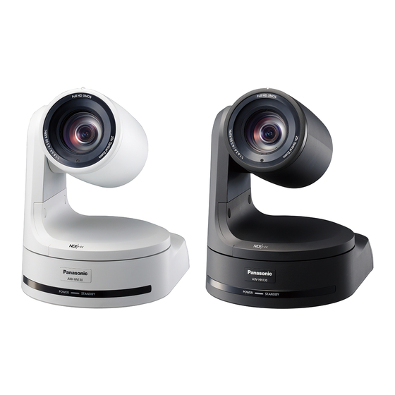
AW‑HN130WP
Model No.
AW‑HN130KP
Model No.
HD Integrated Camera
ENGLISH
DVQP1710ZA
Advertisement
Table of Contents

Related Manuals for Panasonic AW-HN130KP


Summary of Contents for Panasonic AW-HN130KP
- Page 1 Operating Instructions HD Integrated Camera AW‑HN130WP Model No. AW‑HN130KP Model No. Before operating this product, please read the instructions carefully and save this manual for future use. Please carefully read the “Read this first!” (pages 2 to 3) of this Manual before use. ENGLISH DVQP1710ZA W0218TY0 -FJ...
-
Page 2: Read This First
Operation at a voltage other than 120 V AC may require the use of a different AC plug. Please contact either a local or foreign Panasonic authorized service center for assistance in selecting an alternate AC plug. indicates safety information. - Page 3 Read this first! (continued) FCC NOTICE (USA) This device complies with part 15 of the FCC Rules. Operation is subject to the following two conditions: (1) This device may not cause harmful interference, and (2) this device must accept any interference received, including interference that may cause undesired operation.
-
Page 4: Note On Grounding
HDMI Licensing Administrator, Inc. in the United States and other AW-HN130WP countries. AW‑HN130 AW-HN130KP • NDI is a registered trademark of NewTek, Inc. • Other names of companies and products contained in these AW-HS50N AW‑HS50 Operating Instructions may be trademarks or registered AW-HS50E trademarks of their respective owners. -
Page 5: Table Of Contents
Contents Read this first! ..................2 Matrix 4/5 screen ................49 Note on grounding ................4 Matrix 5/5 screen ................49 System screen ................... 50 Before use ....................6 Genlock screen .................. 50 Overview ....................6 Output screen ..................51 Computer requirements ............... -
Page 6: Before Use
• Connection with a Panasonic camera controller is also possible via Panasonic's proprietary serial communication format. OS X 10.8 Safari 6.1.2 • The unit is available in white (AW-HN130WP) or black (AW-HN130KP) OS X 10.7 to suit your intended application and environment. Safari 6.1.2 For iPhone, iPad, iPod touch: iOS 7.1... -
Page 7: Disclaimer Of Warranty
Disclaimer of warranty • Protect your network against unauthorized access by restricting users IN NO EVENT SHALL Panasonic Corporation BE LIABLE TO ANY to those who log in with an authorized user name and password. PARTY OR ANY PERSON, EXCEPT FOR REPLACEMENT OR •... -
Page 8: Features
The unit can also be used together with the cameras and pan-tilt manual. head unit systems currently available from Panasonic Corporation For details on PoE+ power supply devices for which operation so that an existing system can be used to advantage to put has been verified, consult your local dealer. -
Page 9: Controller Supported
• It may be necessary to upgrade the version of the controller in order to support the unit. For details on upgrading, visit the support page on the following website. http://pro‑av.panasonic.net/ <NOTE> • The following operations can not be performed via the following controllers. -
Page 10: Accessories
Accessories Check that the following accessories are present and accounted for. • After removing the product from its container, dispose of the power cable cap (if supplied) and packing materials in an appropriate manner. Mount bracket for installation surface Main unit mounting screw (with flat AC adaptor (1) (Hanging / Desktop) (1) washer, spring washer) -
Page 11: Operating Precautions
Operating precautions Shoot under the proper lighting conditions. Concerning the HDMI interface standard „ „ „ „ To produce pictures with eye-pleasing colors, shoot under the This unit has been certified as HDMI-compatible, but on rare proper lighting conditions. occasions images may not be displayed depending on the HDMI The pictures may not appear with their proper colors when shooting device which has been connected to the unit. - Page 12 This product includes MIT Licensed software. This product includes BSD Licensed software. For details on obtaining the source codes, visit the following website. http://pro-av.panasonic.net/ However, do not contact Panasonic for questions regarding obtained source codes.
-
Page 13: Wireless Remote Control (Optional Accessory)
Wireless remote control (optional accessory) This unit can be operated by remote control using a wireless <Layout of wireless remote control signal light‑sensing areas> remote control (model number: AW‑RM50G) purchased separately. Check out the following points before using the wireless remote <NOTE>... -
Page 14: Parts And Their Functions
Parts and their functions Camera unit Mount bracket for installation surface (supplied accessory) Mount this bracket onto the installation surface, and then attach the camera main unit to the bracket. Drop‑prevention wire This wire is screwed down to the bottom panel of the camera main unit. - Page 15 1080/50i address setting 1080/25p 576/50i — (standard serial 1080/50i 576/50i 1080/50i communication) 576/50i 1080/50i 1080/25PsF Communication Panasonic Standard serial 720/50p 576/50i 720/50p format proprietary serial communication 576/50p(i) 576/50i ― communication <NOTE> Always leave at OFF (used for factory adjustments) • Locking to a subcarrier is not possible with BBS.
- Page 16 Selects the communication format. When this is set to ON, standard serial communication is enabled. 1080/25p When this is set to OFF, Panasonic's proprietary serial 1080/23.98p communication is enabled. 720/59.94p ...
-
Page 17: Wireless Remote Control (Not Supplied)
Parts and their functions (continued) Wireless remote control (not supplied) MODE button <MODE> This is used to select the video signals which are output from the unit. Each time it is pressed, the signals are switched between the color bar signals and camera video signals. <NOTE>... - Page 18 Parts and their functions (continued) <NOTE> • To prevent malfunctioning, there are a number of menu items ([Scene], [Format], [Down CONV. Mode] and [Frequency]) whose setting is not reflected immediately even if it is changed while it is still flashing. It is reflected only after the <M>...
-
Page 19: Setting The Remote Control Ids
Setting the remote control IDs The wireless remote control (optional accessory) is capable of operating up to four units. IDs are used to set which units are selected when the <CAM1>, <CAM2>, <CAM3> and <CAM4> buttons on the wireless remote control have been pressed. -
Page 20: Network Settings
Easy IP Setup Software. You can obtain Easy IP Setup Software (EasyIPSetup.exe) by downloading it from the following website. http://pro-av.panasonic.net/ To establish the settings for a multiple number of units, the settings must be selected for each camera involved. If the settings cannot be established using the Easy IP Setup Software, select the settings separately for the unit and personal computer on the Network setup screen [Network] of the setting menu. -
Page 21: Installing The Plug-In Viewer Software
Setting the remote control IDs (continued) Installing the plug‑in viewer software User authentication To view IP images from the unit on a web browser, the "Network The unit can be configured to allow access from the internet. To Camera View 4S" plug-in viewer software (ActiveX ®... -
Page 22: Basic Shooting Operations
Basic shooting operations Set the subject brightness to the appropriate level. Start shooting. (After shooting, turn off the power of all the units and Turn on the power of all the units and devices in the devices in the system.) system. -
Page 23: Selecting The Units
Selecting the units Up to four units can be operated using one wireless remote control. Up to five units can be operated using one controller. Select the unit (or units) to be operated from the wireless remote control or controller. Even when using only one unit, it must still be selected. -
Page 24: Selecting The Shooting Modes (Scene Files)
Selecting the shooting modes (scene files) Press the <M> button. Types of shooting modes The [Camera] sub-menu is displayed on the monitor. One of four shooting modes (Scene1, Scene2, Scene3 or Scene4) — C am e ra whichever one will best suit the shooting conditions — can be selected. The shooting modes are set by the user. -
Page 25: Shooting
Shooting When performing operations from a wireless When performing operations from a controller remote control Changing the camera’s direction „ „ Changing the camera’s direction Moving the camera toward the left or right (panning): „ „ Tilt the <PAN/TILT> lever toward L or R. Moving the camera toward the left or right (panning): Press the <b>... -
Page 26: What To Do When Encountering Problems In The Basic Shooting Operations
What to do when encountering problems in the basic shooting operations When performing operations from a controller If the trouble is not resolved by taking the action suggested below, refer to “Troubleshooting” (→ page 109). The unit does not move. When performing operations from a wireless •... -
Page 27: Manual Shooting
Manual shooting Manually adjusting the focus Manually adjusting the shutter speed The lens focus can be adjusted manually. The shutter speed can be set using two methods. One is a method that specifies the time (where a time such as 1/250 sec. is designated), and When performing operations from a wireless the other is a method that specifies the frequency (where synchro scan, 60.15 Hz, etc. -
Page 28: Preset Memories
Preset memories When performing operations from a wireless This unit enables up to 100 settings for the camera direction (panning and tilting), zoom, focus, iris, gain and white balance to be registered in remote control its preset memories, and called. However, the number of settings that can be registered and called Twelve settings (preset No.1 to No.12) can be registered and called depends on the type of wireless remote control or controller that is used... -
Page 29: White Balance Adjustment
White balance adjustment Adjust the ratio between the three primary colors (RGB) to reproduce Automatic adjustment (AWB: AWB A or AWB B) white accurately. If the white balance is out of adjustment, not only will When performing operations from a wireless white be reproduced poorly, but the color tones of the screen as a whole will also be degraded. -
Page 30: Auto Tracking White Adjustment (Atw)
White balance adjustment (continued) Press the <SET> button for 2 seconds. 3200K and 5600K presets The auto white balance adjustment (AWB) and auto black balance When [3200K] or [5600K] is selected for the white balance, the white adjustment (ABB) are performed, and the white balance setting is balance is set using a color temperature of 3200 K (equivalent to entered. -
Page 31: Black Balance Adjustment
Black balance adjustment When performing operations from a controller Adjust the zero levels of the three primary colors (RGB) to reproduce black accurately. If the black balance is out of adjustment, not only will black be reproduced poorly, but the color tones of the screen as a whole When using an AW‑RP50, AW‑RP120, or AK‑HRP200 will also be degraded. -
Page 32: Black Level (Master Pedestal) Adjustment
Black level (master pedestal) adjustment When performing operations from a controller The black level can be adjusted when using a multiple number of cameras including the unit. Ask your dealer to perform this adjustment. (Use an oscilloscope or waveform monitor for the adjustment.) When using an AW‑RP50, AW‑RP120, or AK‑HRP200 Adjust the black level in accordance with the units and devices used. -
Page 33: Genlock Adjustment
Genlock adjustment Press the <4> or <5> button to bring the cursor to The genlock adjustment is performed to achieve phase alignment by applying external synchronization (genlock) when a multiple number of [Genlock], and press the <M> button. cameras will be used or when the unit will be used in combination with The [Genlock] sub-menu is displayed. -
Page 34: Basic Setup Operations
AW-RP120: Ver 2.00.00 or later AK-HRP200: Ver 4.00-00-0.00 or later If the version older, an upgrade is required. For details on upgrading, visit the support page on the following website. http://pro-av.panasonic.net/ Wireless remote control and controller operations „ „ Controller... -
Page 35: When Performing The Operations Using The Wireless Remote Control
Basic setup operations (continued) When performing the operations using the wireless remote control Press the <CAM1>, <CAM2>, <CAM3> or <CAM4> button to select the unit which is to be operated. Press and hold the <MENU> button for about 2 seconds. The Top Menu is displayed. -
Page 36: Operations On The Aw-Rp50 Remote Camera Controller
Basic setup operations (continued) Operations on the AW‑RP50 Remote Camera Controller For operating the camera menus. POWER ALARM CAMERA CAMERA OSD: When this is pressed for 2 seconds, the selected camera menu is displayed, overlapping MENU PAGE EXIT GAIN/PED R/B GAIN R/B PED AWB/ABB SHUTTER... - Page 37 Basic setup operations (continued) Preset speed table setting (PRESET SPEED) Digital extender setting (D.EXTENDER) „ „ „ „ Press the <MENU> button on the AW‑RP50. Press the <MENU> button on the AW‑RP50. The <MENU> button lights, and the <PRESET MEMORY/MENU> The <MENU>...
-
Page 38: Operations On The Aw-Rp120 Remote Camera Controller
Basic setup operations (continued) Operations on the AW‑RP120 Remote Camera Controller For operating the camera menus. CAMERA OSD: When this is pressed for 2 seconds, the selected camera menu is displayed, overlapping the camera output image. When it is pressed for 2 seconds while a camera menu is displayed, the menu is exited. - Page 39 Basic setup operations (continued) Freezing images during preset playback Assigning “FREEZE DURING”, “COLOR „ „ „ „ (FREEZE DURING) TEMP”, and “D.EXT” to the <USER> buttons Press the <MENU> button on the AW‑RP120. You can assign the on/off functions for freezing images during preset playback (FREEZE DURING), color temperature settings (COLOR The <MENU>...
-
Page 40: Operations On The Ak-Hrp200 Remote Operation Panel
Basic setup operations (continued) Operations on the AK‑HRP200 Remote Operation Panel AUTO HEAD POWER POWER BARS WHITE BLACK SET UP TEST KNEE SHUTTER 5600K MATRIX SKINDTL STEP/SYNC SCENE/USER FILE SHIFT SCENE 1 SCENE 2 SCENE 3 SCENE 4 STORE USER 1 USER 2 USER 3 GAIN... - Page 41 Basic setup operations (continued) The following operations can be performed from the AK-HRP200 Remote Operation Panel. For details on operations, refer to the AK-HRP200 Operating Instructions <Basics>. Control/display component Label AW‑HN130 Remarks Camera power switch HEAD POWER Supported VF power switch VF POWER ―...
- Page 42 Basic setup operations (continued) Control/display component Label AW‑HN130 Remarks Only enabled during MENU ON. When ZOOM is selected, FOCUS adjustment is possible on the selection Rotary selection switch SELECT Supported dial. When FOCUS is selected, ZOOM adjustment is possible on the selection dial.
-
Page 43: Camera Menu Items
Camera menu items Setting the camera menu items Top menu (Top Menu) screen Camera menus are displayed on the monitor when the unit’s settings are T o p M en u to be selected. The monitor is connected to the video signal output connector. C am e ra Sc en e : Sc e ne 1 The basic camera menu operations involve displaying sub-menus from... -
Page 44: Camera Screen
Camera menu items (continued) Camera screen Brightness 1/2 screen This menu is used for the camera image settings. This menu item is selected to set the brightness of the pictures. C am e r a B r i g h t n e s s 1 / 2 S cen e Scene1 P i c t u r e L e v e l... -
Page 45: Brightness 2/2 Screen
Camera menu items (continued) When 50 Hz has been set as the unit’s frequency: Brightness 2/2 screen When [Step] is When [Synchro] selected as the is selected as the B r i g h t n e s s 2 / 2 [Shutter Mode] [Shutter Mode] For 50p/ 50i... -
Page 46: Picture 1/3 Screen
Camera menu items (continued) Picture 1/3 screen Picture 2/3 screen Pic tur e 1/ 3 P i c t u r e 2 / 3 Ch roma Lev el D e t a i l Wh ite B ala nc e M od e AW B A M a s t e r D e t a i l C olor Tem pe ra t ur e... -
Page 47: Picture 3/3 Screen
Camera menu items (continued) Picture 3/3 screen Matrix 1/5 screen Pic tur e 3/ 3 M a t r i x 1 / 5 Kn ee Mo de A ut o M a t r i x T y p e N o r m a l K nee P oin t 93 .0 %... -
Page 48: Matrix 2/5 Screen
Camera menu items (continued) Matrix 2/5 screen Matrix 3/5 screen Mat rix 2 /5 M a t r i x 3 / 5 [L in e ar M a tr ix ] [ C o l o r C o r r e c t i o n 1 / 3 ] R- G S a t u r a t i o n P h a s e... -
Page 49: Matrix 4/5 Screen
Camera menu items (continued) Matrix 4/5 screen Matrix 5/5 screen Mat rix 4 /5 M a t r i x 5 / 5 [Col or Co rr e ct io n 2 /3 ] [ C o l o r C o r r e c t i o n 3 / 3 ] S atu ra ti o n Ph as e S a t u r a t i o n... -
Page 50: System Screen
Camera menu items (continued) System screen Genlock screen This menu has items that relate to the genlock phase adjustment and G e n l o c k camera’s output image settings. Syst em H o r i z o n t a l P h a s e H o r i z o n t a l P h a s e S t e p Ge nlock Ou tput... -
Page 51: Output Screen
Camera menu items (continued) Frequency [59.94Hz, 50Hz] Output screen This item is selected to switch the frame frequency. • When the frequency is switched, [Format] is set as follows. Out put 59.94Hz 50Hz Fo rmat 1 08 0/ 5 9. 94 i 1080/59.94p 1080/50p ... - Page 52 Camera menu items (continued) Changing the format Changing the frequency „ „ „ „ When the currently selected format is changed in the [Output] screen, When the currently selected frequency is changed in the [Output] the pre-format-change confirmation screen appears. screen, the pre-frequency-change confirmation screen appears.
-
Page 53: Others 1/4 Screen
Camera menu items (continued) Others 1/4 screen Others 2/4 screen Ot hers 1 /4 O t h e r s 2 / 4 I nstal l Po si ti o n D e sk to p F r e e z e D u r i n g P r e s e t O f f S mart Pict ur e F li p Of f... -
Page 54: Others 3/4 Screen
Camera menu items (continued) Others 3/4 screen Others 4/4 screen O thers 3 / 4 O th e r s 4 /4 Tally E na b le O S D O ff W it h T a l ly O ff Tally Brig ht n es s L ow O S D S ta t u s... -
Page 55: Maintenance Screen
Camera menu items (continued) Maintenance screen Firmware VER 1/2 screen Ma i n t e nance Fi r mw ar e V ER 1/ 2 Fi rmw a r e Versio n C PU So f tw ar e IP Ne t w o r k In t er f ac e V0 1 .0 0 In iti a l i z e... -
Page 56: Ip Network Screen
Camera menu items (continued) Menu settings initialized screen IP Network screen IP Net wo rk IP Addr ess M en u s e tt in g s 19 2. 1 68 . 0. 1 0 Su bnet Mas k i ni t ia l iz ed 25 5. -
Page 57: Camera Menu Item Table
Camera menu item table Camera menu Item Factory setting Selection items Top Menu Camera Scene Scene Scene1 Scene1, Scene2, Scene3, Scene4 Brightness Brightness Picture Level -50 to +50 (step: 1) Iris Mode Auto Manual, Auto Shutter Mode Off, Step, Synchro, ELC When Frequency is set to 59.94 Hz : Step/Synchro [59.94Hz]... - Page 58 Camera menu item table (continued) Camera menu Item Factory setting Selection items Top Menu Camera Scene Matrix Matrix 1/5 Matrix Type Normal Normal, EBU, NTSC, User Matrix 2/5 [Linear Matrix] Normal EBU NTSC User -63 to +63 -63 to +63 -63 to +63 -63 to +63 -63 to +63...
- Page 59 Camera menu item table (continued) Camera menu Item Factory setting Selection items Top Menu System Others Others 1/4 Install Position Desktop Desktop, Hanging Smart Picture Flip Off, Auto Flip Detect Angle 90deg 60 to 120deg (step: 1deg) Preset Speed Table Fast Slow, Fast Preset Speed...
-
Page 60: Displaying The Web Screen
Displaying the web screen With a personal computer connected to the unit, it is possible to view the Displaying the web screen using a personal camera’s IP videos or select various settings from the web browser. computer The LAN crossover cable is used when connecting a personal computer The procedure is explained here using Windows screens (Internet directly to the unit’s LAN connector for IP control, and the LAN straight Explorer), but it is the same when using the Mac (Safari) -
Page 61: Switching Between The Live Screen [Live] And Web Setup Screen [Setup]
Displaying the web screen (continued) <NOTE> Switching between the Live screen [Live] and • If the personal computer does not have the plug-in viewer software Web setup screen [Setup] already installed, an installation confirmation message is displayed before the live screen [Live] is displayed. In a case like this, follow When the live screen [Live] is displayed, click the button. -
Page 62: Web Screen Operations
Web screen operations The live screen [Live] includes a “single display mode” that displays IP images from a single camera and a “multi display mode” that displays IP images from multiple cameras. See below for details on the single display mode, and see page 66 for details on the multi display mode. Live screen [Live] : Single display mode You can display images from the camera on a personal computer and perform camera operations, such as pan, tilt, zoom, and focus control. - Page 63 Web screen operations (continued) Menu switching [OSD Menu >>] / [Stream Menu >>] Image quality buttons [Image quality] Switch between menu displays. These buttons appear only when JPEG images are displayed. Clicking [OSD Menu >>] when the Stream menu is displayed displays When selected, images appear according to the the OSD menu.
- Page 64 Web screen operations (continued) Power ON button [Power ON] / Standby button [Standby] <NOTE> • When the shooting scenes vary significantly, restrictions imposed by the graphics processing (GDI) of the operating system installed Turn the unit on. may give rise to a phenomenon called “screen tearing” (where parts [Power ON] of the picture are not displayed in synchronization) although this will depend on the personal computer used.
- Page 65 Web screen operations (continued) Control pad and its buttons Full‑screen display button To adjust the image in the horizontal or vertical Display the image in full-screen mode. direction (panning or tilting), left-click the pad and When the image displayed in the main area is the buttons.
-
Page 66: Live Screen [Live] : Multi Display Mode
Web screen operations (continued) Live screen [Live] : Multi display mode In this mode, the images of a multiple number of cameras can be monitored on one screen (called the ‘multi screen’). The image of 4 cameras or max. 16 cameras can be monitored at one time. When the camera title of any of the images is clicked, the live screen [Live] (single display mode) of the camera concerned is displayed as a separate window. -
Page 67: Web Screen Configurations
Web screen configurations Logging into the Web setup screen [Setup] Click the [Setup] button. (→ page 61) Click the [OK] button. The login screen appears. Click [OK] again when the following screen appears. <NOTE> • While the initial settings remain used for the user name and password, a message prompting the user to change the user name and password is displayed after authorization. -
Page 68: Basic Screen [Basic]
Web screen configurations (continued) Power ON button [Power ON] / Time & date ‑ Time zone Standby button [Standby] Selects the time zone according to the region where the camera is being used. Factory settings: Turn the unit on. (GMT) Greenwich Mean Time: Dublin, Edinburgh, Lisbon, London [Power ON] Time &... -
Page 69: Image Screen [Image]
Web screen configurations (continued) Image screen [Image] IP video settings tab [Video over IP] „ „ The JPEG image and H.264 image settings as well as the settings related to image quality are selected on this screen. z Initial display settings for “Live” page „... - Page 70 Web screen configurations (continued) Refresh interval (JPEG) z H.264(1) • H.264(2) • H.264(3) • H.264(4) „ Select the frame rate for JPEG images. Specify the [Max bit rate (per client)], [Image capture size], [Image Setting value: quality], and other settings for H.264 images. For 59.94Hz: For details on setting the JPEG images, see “JPEG”...
- Page 71 Web screen configurations (continued) Transmission priority Max bit rate (per client) Set the transmission mode for H.264 images. Specify the H.264 bit rate per client. Setting value: When [Transmission priority] is set to [Best effort], specify the maximum and minimum bit rate. Constant bit rate Transmits H.264 images at the bit rate specified Setting value:...
- Page 72 Web screen configurations (continued) Transmission type Multicast address Select the transmission format for H.264 images. Enter the multicast IP address. Setting value: Images and audio will be sent to the specified IP address. Usable values: Unicast port Up to 14 users can access a single camera at the IPv4: 224.0.0.0 to 239.255.255.255 (AUTO) same time.
- Page 73 Web screen configurations (continued) Audio [Audio] Mic input interval „ „ Selects the mic input interval. Configure audio settings. Setting value: 20msec / 40msec / 80msec / 160msec <NOTE> Factory settings: 40msec • Images and audio are not synchronized. Therefore, images and audio <NOTE>...
- Page 74 Web screen configurations (continued) z Image adjust screen [Image adjust] Shutter Mode „ Select for camera shutter speed. Adjust the image quality. When a higher shutter speed is selected, fast-moving subjects do not To display the Image adjust screen, click the [Setup] button for [Image become blurred easily but the images will be darker.
- Page 75 Web screen configurations (continued) Frame Mix Picture Select for frame addition (gain-up using sensor storage) amount. When frame addition is performed, it will appear as if the images are missing some frames. Setting value: Off / 6dB / 12dB / 18dB / 24dB Factory settings: Off •...
- Page 76 Web screen configurations (continued) Chroma Level Pedestal This item is used to adjust the black level (adjust the pedestal). Set here the color intensity (chroma level) of the images. Setting range: OFF, -99% to 40% These parts become darker when a negative setting is selected and, Factory settings: 0% conversely, lighter when a positive setting is selected.
- Page 77 Web screen configurations (continued) Gamma z Matrix settings screen [Matrix Settings] „ Adjust the gamma correction level. Set matrix settings. Specifying smaller values results in a gentler gamma curve for the To display the Matrix Settings screen, click the [Setup] button for [Matrix slope of low-brightness areas and sharper contrast.
- Page 78 Web screen configurations (continued) Matrix Type z Preset position screen [Preset position] „ Select the type of color matrix. Perform operations and adjustments related to preset positions. Setting value: To display the Preset position screen, click the [Setup] button for [Preset position] in the image adjust / preset position screen [Image/Position].
- Page 79 Web screen configurations (continued) Zoom Speed With Zoom POS. “Off” or “On” is set here for the function used to adjust the pan-tilt Use this to adjust the zoom (magnification) in the Wide adjustment speed in conjunction with the zoom magnification. direction.
- Page 80 Web screen configurations (continued) Limitation Setting System screen [System] „ „ This establishes the up, down, left and right limit settings of the pan- This menu has items that relate to the genlock phase adjustment and tilt head. camera’s output image settings. First, move the pan-tilt head to the position where the limit is to be set, and press the corresponding button below to set the direction (up, down, left or right) in which the limit is to be set.
- Page 81 Web screen configurations (continued) z Output 1/3 Color Bars Setup „ This item’s setting is reflected when the [Set] button is pressed. This is only enabled when [Frequency] is set to [59.94Hz]. Select the color bar setup level (Off: 0.0IRE, On: 7.5IRE) for the Format VIDEO OUT signal.
- Page 82 Web screen configurations (continued) Preset D‑Extender Turns the preset digital extender function off/on. Enable or disable the optical image stabilization (OIS) function. When set to [On], the digital extender function configuration will be Setting value: Off/On Factory settings: Off recalled when regenerating the preset memory. When set to [Off], the digital extender function configuration will not be recalled when <NOTE>...
-
Page 83: Multi Screen Setup Screen [Multi-Screen Setup]
Web screen configurations (continued) Camera title Multi screen setup screen [Multi‑Screen setup] Input the camera title here. The camera title which has been input is The cameras whose images are to be displayed on the multi screen are displayed on the multi screen. set here. -
Page 84: User Management Screen [User Mng.]
Web screen configurations (continued) Password / Retype password User management screen [User mng.] Input the password. The users and personal computers (IP addresses) that can access the Maximum number of characters 4 to 32 half-size characters unit from personal computers and mobile terminals are registered in the Invalid characters "... - Page 85 Web screen configurations (continued) Host authentication screen [Host auth.] Priority stream screen [Priority stream] „ „ „ „ Click the Host auth. tab of User mng. screen. Click the [Priority stream] tab of User mng. screen [User mng.]. Configure the host authorization settings that restrict the personal Selected on this screen are the settings for the priority stream which computers (IP addresses) that can access the unit.
-
Page 86: Network Setup Screen [Network]
Web screen configurations (continued) z IPv4 network „ Network setup screen [Network] Configure network settings in the Network setup screen. Network Settings The Network setup screen consists of the two tabs of “Network” and Select the method in which the IP address is configured. “Advanced”. - Page 87 Web screen configurations (continued) z IPv6 network Max RTP packet size „ Specify whether to limit the size of RTP packets sent from the camera Manual when using RTP to view camera images. Setting value: Enable or disable manual configuration of the IPv6 address. Setting value: Unlimited (1500byte) Unlimited (1500 byte)
- Page 88 Web screen configurations (continued) Advanced network setting screen [Advanced] „ „ WAN global address LAN private address Click the [Advanced] tab in the network setup screen [Network]. vvv.xxx.yyy.zzz 192.168.0.254 Settings relating to the NTP, UPnP, HTTPS, SNMP, and Diffserv functions are performed here. Enter "<global address from Click the links to each item to move to the respective setting page.
- Page 89 Web screen configurations (continued) NTP port <NOTE> • The port number may be changed by automatic port forwarding. If Input the port No. of the NTP server. the number is changed, the port No. of the camera registered to the Port Nos.
- Page 90 Web screen configurations (continued) Self‑signed Certificate ‑ Generate <NOTE> • This unit will restart if the connection method is changed. A self-signed security certificate is generated by HTTPS. (Self-signed • When using a self-signed certificate: Certificate) A warning screen is displayed when accessing the camera by To generate a self-signed certificate (security certificate), click the HTTPS for the first time.
- Page 91 Web screen configurations (continued) SNMPv3 ‑ User name Input the user name for user authentication. The user name that you input here will need to be specified in the SNMPv3 manager. Maximum number 0 to 32 characters of characters Invalid characters Full-size characters Factory settings: blank SNMPv3 ‑...
- Page 92 Web screen configurations (continued) HTTPS settings [HTTPS] „ „ This encrypts access to the camera and sets HTTPS to improve communication safety. Setting HTTPS is performed by following the procedures below. 1. Generating a CRT key (SSL encryption key) (→ page 93) When using self-signed certificates When using server certificates 2.
- Page 93 Web screen configurations (continued) Generating a CRT key (SSL encryption key) Generating a self‑signed certificate „ „ „ „ [CRT key generate] [Self‑signed Certificate ‑ Generate] <NOTE> <NOTE> • A CRT key cannot be generated when self-signed certificates and • A self-signed certificate cannot be generated when a CRT key has not server certificates are enabled.
- Page 94 Web screen configurations (continued) Click the [OK] button after inputting the address. Input information relating to the certificate to be A self-signed certificate is generated. generated <NOTE> Items to be entered are as follows. • Information relating to the generated self-signed certificate is Maximum number Item Description...
- Page 95 Web screen configurations (continued) Installing a Server Certificate Setting the Connection Method [Connection] „ „ „ „ [CA Certificate ‑ CA Certificate install] Set the method to access the camera in [Connection]. <NOTE> HTTP: Only HTTP connection is possible. • A server certificate (security certificate) cannot be installed if a HTTPS: Only HTTPS connection is possible.
- Page 96 Web screen configurations (continued) z Install the security certificate Click [Install Certificate...]. „ When using HTTPS to access the camera, the security warning screen will be displayed if the security certificate of the said camera has not been installed in your personal computer. To prevent this warning screen being displayed, the security certificate must be installed in accordance with the following procedures.
- Page 97 Web screen configurations (continued) Select [Place all certificates in the following store] and Click [Finish]. click [Refer (R)..]. Click [Yes]. Select [Trusted Root Certification Authorities] and click [OK]. Click [Next]. When importing is finished, the “Certificate was imported correctly” screen is displayed. Click [OK].
-
Page 98: Maintenance Screen [Maintenance]
Web screen configurations (continued) Serial no. Maintenance screen [Maintenance] Display the unit’s serial number. Among the various maintenance operations performed on this screen are system log checks, system version upgrading and initialization of the Firmware version unit. The Maintenance screen consists of five tabs: [System log], [Product CPU Software ‑... - Page 99 • Before using the version upgrading software, be absolutely sure to check the precautions to be observed with your dealer, and follow the dealer’s instructions. • Use the following files specified by Panasonic Corporation as the software used for version upgrading. CPU Software Interface .sif files...
- Page 100 Web screen configurations (continued) Reset settings screen [Default reset] Back up screen [Back up] „ „ „ „ The unit’s setting data is initialized and the unit is restarted on this On this screen, the unit’s settings can be saved to a personal computer screen.
-
Page 101: Displaying The Web Screen Using A Mobile Terminal
• For the latest information on compatible operating systems and web browsers, visit the support desk at the following website. http://pro-av.panasonic.net/ • Use a standard web browser with an Android terminal. • Images are displayed only in the JPEG format when using the standard web browser of an Android terminal. - Page 102 Displaying the web screen using a mobile terminal (continued) Preset Resolution switching When this button is pressed, the buttons for selecting the preset When this button is pressed, the buttons for selecting the resolution positions are displayed on the screen. are displayed on the screen.
- Page 103 Displaying the web screen using a mobile terminal (continued) Iris Focus When this button is pressed, the buttons for performing the iris When this button is pressed, the buttons for performing the focusing operations are displayed on the screen. operations are displayed on the screen. Use this to switch between auto and manual focusing.
- Page 104 Displaying the web screen using a mobile terminal (continued) <NOTE> • If the HTTP port number has been changed from “80”, enter “http://<IP Camera menu (OSD menu) operation address>:<port number>/mobile” to specify the unit’s port number. • When [HTTPS] - [Connection] (→ page 90) is set to [HTTPS] in the [Advanced] tab of the Network setup screen [Network], enter the following.
-
Page 105: System Log Displays
System log displays NTP‑related error displays Category Display Description Connection error No response from the NTP server. • The IP address of the server may be incorrect. Check the server’s IP address settings again. • The NTP server may be down. Consult your server administrator. -
Page 106: Limiters
Limiters This unit comes with settings (referred to as “limiters”) that restrict the panning and tilting movement ranges. Depending on the installation location, obstacles that may come into contact with the remote camera may exist within its movement range. In such cases, setting the limiters before the obstacles will prevent contact. -
Page 107: Setting/Releasing The Limiters
Setting/releasing the limiters Setting/releasing the limiters Releasing the limiters Press the <MENU> button. The limiter positions that are set can be released by following the steps below. Tap the button (rather than pressing it). When it is pressed for 2 When the position is released, the tally lamp blinks twice. -
Page 108: Safe Mode
Safe mode Concerning the safe mode The unit goes into the safe mode when the pan-tilt head is forcibly moved by an external force or when something impedes its rotation. Once the safe mode has been established, some or all of the operations will no longer be acknowledged to ensure safety and prevent equipment damage. -
Page 109: Troubleshooting
– – – → For details on upgrading, visit the support page on the following website. http://pro-av.panasonic.net/ • When using an HTTPS connection, network connection with the AW‑RP50, AW‑ page 90, page 95 RP120, and AK‑HRP200 will be disabled. - Page 110 Troubleshooting (continued) Symptom Cause and solution Reference pages • Has a LAN cable of category 5 or above been connected to the LAN connector Installation Instructions for IP control <NDI|HX>? • Is the [LINK] LED of the LAN connector for IP control lit? →...
- Page 111 Troubleshooting (continued) Symptom Cause and solution Reference pages For Windows: • Press the [F5] key on the keyboard of the personal computer to request that the settings be acquired. – – – For Mac: • Press the [Command] + [R] key on the personal computer's keyboard to request that the settings be acquired.
- Page 112 Troubleshooting (continued) Symptom Cause and solution Reference pages • Is access being performed in HTTPS mode? Screen displays may take a while to appear in HTTPS mode due to signal – – – processing. Screens displays take a while to •...
- Page 113 Troubleshooting (continued) Video „ „ Symptom Cause and solution Reference pages • Has the unit been connected properly to the other connected devices? Installation Instructions • If the system is configured in such a way that the picture is also switched when page 23 the unit to be operated is selected, has the correct unit been selected? No pictures are displayed or the...
- Page 114 Troubleshooting (continued) Symptom Cause and solution Reference pages • Activate the ATW (Auto tracking white adjustment) function. page 30 Something is wrong with the • In some situations, the proper colors may not be reproduced using the ATW coloring of the pictures function.
- Page 115 Troubleshooting (continued) IP images „ „ Symptom Cause and solution Reference pages For Windows: • Is the plug‑in viewer software installed? page 21 → Install the plug-in viewer software. For Windows: • If [Check for newer versions of stored pages] is not set to [Every time I visit the webpage] in the temporary Internet file settings, IP images may not appear in the Images are not displayed live screen [Live].
- Page 116 Troubleshooting (continued) Symptom Cause and solution Reference pages • The images may be distorted if the transmission path is congested and proper transmission is not possible. – – – → Consult your network administrator. The images are distorted • The images may be distorted if video packet shuffling occurs on the transmission path.
- Page 117 "This website wants to run the • Select [Allow]. – – – following add‑on: 'WebVideo Module' from 'Panasonic System Networks Co.,Ltd.'." For Internet Explorer 8.0: • Click the information bar, and select [Always Allow Pop‑ups from This Site]. The following message appears in When the [Allow pop‑ups from this site?] dialog box appears, click the [Yes]...
-
Page 118: Specifications
642.5 mm) Finish: AW-HN130WP: Pearl white Focus: Switching between auto and manual AW-HN130KP: Metallic black Focus distance: Entire zooming range: 800 mm (2.62 ft) Controller supported: Wide end: 400 mm (1.31 ft) AW-RP120, AW-RP50, AK-HRP200 • It may be necessary to upgrade the version of the Color separation optical system: controller in order to support the unit. - Page 119 Specifications (continued) Chroma amount variability: AC adaptor „ „ OFF, -99 % to 40 % Input : 100 V - 240 V AC ( ), 50 Hz/60 Hz, 1.2 A Scene file: Scene1, Scene2, Scene3, Scene4 Output : 12 V DC ( ), 3.0 A, 36 W Output format: 1080/59.94p, 1080/29.97p...
-
Page 120: Index
Index Numerics 3200K ....................Day/Night ..................5600K ....................DC IN connector .................. Default gateway ................Default Gateway .................. Default reset ..................ABB ..................... Description ................... Access level .................. Destination IP address (1) ..............Accessories ..................Destination IP address (2) ..............Activation .................. - Page 121 Index (continued) Master pedestal ................... Matrix ................Matrix Settings ..................H.264(1) • H.264(2) • H.264(3) • H.264(4) ........... Matrix Type ................... H.264 transmission ................Max bit rate (per client) ................ HDMI connector ................... Max Digital Zoom ................HDMI Out ..................Max RTP packet size ................
- Page 122 Index (continued) Reboot ....................Tally ....................Recommended network setting for internet ......... Tally Brightness ................Refresh interval ................Tally lamp ................... Refresh interval (JPEG) ............... Tilt ...................... Remote control IDs ................Tilt head ....................Reset to the default (Except thenetwork settings) ......Time adjustment ..................
- Page 123 MEMO...
- Page 124 Web Site: http://www.panasonic.com © Panasonic Corporation 2018...