
Related Manuals for NCR 7455


Summary of Contents for NCR 7455
- Page 1 NCR 7455 Retail Terminal Release 1.1 Hardware User’s Guide 1842 B005-0000-1285 Issue D...
- Page 2 NCR, therefore, reserves the right to change specifications without prior notice. All features, functions, and operations described herein may not be marketed by NCR in all parts of the world. In some instances, photographs are of equipment prototypes. Therefore, before using this document, consult with your NCR representative or NCR office for information that is applicable and current.
-
Page 3: Safety Warnings
Audience This book is written for hardware installer/service personnel, system integrators, and field engineers. Notice: This document is NCR proprietary information and is not to be disclosed or reproduced without consent. Safety Warnings This equipment is intended for use with an IT power system with a line-to- line voltage of 240 V or less. - Page 4 Peripheral Usage This terminal should only be used with peripheral devices that are certified by the appropriate safety agency for the country of installation (UL, CSA, TUV, VDE) or those which are recommended by NCR Corporation. Environmental Consciousness NCR is demonstrating its concern for the environment by designing an...
-
Page 5: Table Of Contents
Table of Contents Chapter 1: Product Overview Introduction ..............1-1 Serial Number/Model Number Label ......1-2 Hardware Modules ............1-3 Base Unit ..............1-3 Hardware Options ..........1-4 System Configuration Diagram........1-7 Hardware Module Descriptions........1-8 Processor Board............1-8 Processor/Chip Set ..........1-8 Video Subsystem.......... - Page 6 DynaKey ............1-22 Touch Screen (Optional) ........1-22 NCR 7455 Remote Displays......... 1-23 4x20 VFD Customer Display......1-23 NCR 5972 2x20 VFD Customer Display..1-23 NCR 5973 International VFD Customer Display.............. 1-23 Table Top Mount..........1-24 16" High Post Mount........1-24 Features ...............
- Page 7 Introduction ..............2-1 Installation Summary..........2-1 Installation Restrictions..........2-2 Connecting the Cables..........2-3 Accessing the Cable Connectors ......2-3 Routing the Cables ..........2-4 Identifying the Cable Connectors ......2-5 Installing Peripherals ........... 2-6 7158 Printer............2-6 7166 Printer............2-7 7194 Printer............
- Page 8 Chapter 3: Setup Introduction ..............3-1 Entering Setup Using a Keyboard......3-1 Entering Setup Without a Keyboard (on units with Touch-Screen) ..........3-2 How to Select Menu Options ........ 3-3 Restoring Factory Settings........3-3 Setup Menus ..............3-4 Main Menu ............. 3-4 System Time and Date ........
- Page 9 Completing the OS Installation (Windows 2000) ..............4-5 Completing the OS Installation (DOS) ..... 4-5 Gold Disk Contents ............4-6 NCR 7455 Win2000 OS Recovery Software..4-6 NCR 7455 NT Operating System Recovery Software ..............4-7 NCR 7455 Win98 OS Recovery Software....4-8 NCR 7455 DOS Operating System Recovery Software ..............
- Page 10 BIOS Crisis Recovery ........... 5-5 Recovery Procedures ..........5-6 Cable/Connector Pin-Out Information ...... 5-9 Appendix A: Cables 7455 Cables..............A-1 Appendix B: Feature Kits Kit Index................B-1...
- Page 11 Revision Record Issue Date Remarks Apr 01 First issue Aug 01 Updates to BIOS screens Nov 01 Added Cable and Feature Kit information Jan 02 Added BIOS Crisis Recovery procedures...
- Page 12 NCR is not responsible for any radio or television interference caused by unauthorized modification of this equipment or the substitution or attachment of connecting cables and equipment other than those specified by NCR.
-
Page 13: Declaration Of Conformity
Class 7455 Model Number 100-240 V/2.0 A/50-60 Hz Electrical Ratings (Input) NCR Corporation, 1700 South Patterson Boulevard, Dayton, OH 45479, USA, declares that the equipment specified above conforms to the referenced EU Directives and Harmonized Standards. EU Directive Harmonized Standard(s) -
Page 15: Chapter 1: Product Overview
The 7455 supports a complete set of peripherals. The major hardware features of the 7455 are a flat panel display with optional touch screen input, DynaKey input device, LAN connectivity, plus optional magnetic stripe reader, CD-ROM, and wireless LAN. -
Page 16: Serial Number/Model Number Label
To view the label, tilt the Core Module and remove the cable cover. Note: The serial number is repeated on the non-MSR side of the Core Module. Class/Model Serial Number 7455-2002-M016 50-34697073 Tracer Number 50-000038 Date Manufactured Mfg Date : 03/16/01... -
Page 17: Hardware Modules
Chapter 1: Product Overview Hardware Modules Base Unit • Processor Board & POS Connector Board − DynaKey User Interface − ® 600 MHz Intel Celeron Processor − 32 MB On-board Memory − SODIMM Memory Socket with support up to 256 MB RAM −... -
Page 18: Hardware Options
Chapter 1: Product Overview • 12.1" Operator Display – Passive (DSTN) or Active (TFT) Matrix Display • Integrated Motion Sensor, capable of waking up the terminal from a low power state • Integrated Power Supply with Table Top Mount • Integrated Keylock •... - Page 19 Chapter 1: Product Overview • Cash Drawers − Compact Cash Drawer (2113) − Full-Size Cash Drawer (2189) − Mid-Range Cash Drawer (7454-K005) − Up to two drawers supported via Y cable • Printers: − 7158 Thermal Receipt Printer w/Slip (MICR and Check Flip) −...
- Page 20 Chapter 1: Product Overview • Electronic Payment Devices: − 5992 Signature Capture Device − 5945 Electronic Payment Device • Power Cords: − US Power Cord − US Twist Lock Power Cord − International Power Cord − Australian Power Cord − UK Power Cord −...
-
Page 21: System Configuration Diagram
Wedge PS/2 NOTE: 7158 & 7196 connect Serial to RS-232 or USB Aux Power Power RS-232 Transaction Printers Parallel 7194 7196 7166 7158 7455 7162 Cash Drawer Aux Power 2189 2113 7454-K005 Ethernet RS-232 Peripherals Cash Drawers Only Only 7892... -
Page 22: Hardware Module Descriptions
Chapter 1: Product Overview Hardware Module Descriptions Processor Board Processor/Chip Set The terminal uses a Celeron processor (µPGA2 package), used with the Intel 440BX PC chipset. The 440BX chipset consists of the 82443BX System Controller and the 82371EB PCI ISA Accelerator, also called the PIIX4E. -
Page 23: Ethernet 10/100Base-T Lan Communications
Category 5 and the hubs must permit 100 or 10/100 MB/s operation. Although 10Base-T will operate on Category 3 twisted pair, or NCR “747” cable, an upgrade to Category 5 is required for 100Base-T. A customer desiring to use the terminal in an existing 10Base-T environment can do so and simply run at 10 MB. -
Page 24: Wireless Lan Communications
Note: It is possible that other LAN PC cards may work; however, NCR does not certify all configurations. Remote Wakeup over the wireless network is not possible because the cards do not support it. An alternative is to use the system real-time... -
Page 25: Universal Serial Bus
Chapter 1: Product Overview 1-11 Depending on the OS environment, Remote Boot may be supported, but due to the slow network speed a large boot image may take an unacceptably long time to load. The application developer needs to ensure that the load is of reasonable size. The wired Ethernet connection is not certified for use in configurations where a wireless adapter is installed. -
Page 26: Hardware Monitor
1-12 Chapter 1: Product Overview Hardware Monitor The hardware monitor generates an interrupt to the system whenever any of the internal voltages used by the system processor goes above or below the acceptable operating range. An interrupt is also generated when the temperature of the Processor exceeds safe levels. -
Page 27: Magnetic Stripe Reader
PS/2 interface. This requires a mouse-aware touch device driver for the appropriate OS. Note: The 7455 does not support PS/2 mouse devices on units that have the optional touch screen because the touch screen uses the PS/2... -
Page 28: Processor Board Connectors
1-14 Chapter 1: Product Overview When the system is operating in the dimmed display mode, touch activity can restore full brightness if instructed by software to do so. When the system is in low power mode, touch activity can generate the mouse port interrupt (IRQ12). -
Page 29: External Motherboard Connectors
Chapter 1: Product Overview 1-15 External Motherboard Connectors • VGA CRT RGB 15-pin D-Shell • Ethernet RJ45 (See warning below) • Dual USB Type A • RS-232 9-pin D-Shell (two, one with +12V power option) • PS/2 Connector—also supports mouse via mouse interface cable •... -
Page 30: Internal Motherboard Connectors
1-16 Chapter 1: Product Overview Internal Motherboard Connectors • • Backlight Inverter • • Touch Screen • Motion Sensor/Power Indicator • PCI Expansion Header • Primary IDE (hard drive) • Secondary IDE (CD-ROM) • POS Connector Board Header • USB Port 3 •... -
Page 31: Flash Disk
CA000, CC000, or D0000. If MSR capability is not desired, it may be disabled through BIOS Setup. Graphics Subsystem The 7455 Retail Terminal is equipped with an SMI Lynx SVGA LCD/CRT 3DM graphics controller with 8 MB of integrated synchronous graphics DRAM. -
Page 32: Board Bios
1-18 Chapter 1: Product Overview Because a hole in memory creates a non-contiguous address space, enabling linear addressing when total system DRAM is greater than 64 MB is not recommended. Video linear addressing is enabled through PC Setup under the Integrated Peripherals menu. The processor also supports VESA standards such as the VESA DPMS protocol to place a DPMS compliant monitor into power savings modes. - Page 33 Chapter 1: Product Overview 1-19 Flash Memory Implementation The Intel E28F800B5-T70 Flash component is organized on board as 1024 K x 8 (1 MB). While a typical PC BIOS image including video and LAN boot ROM code normally fits in 512 K, the board supports a 1 MB Flash ROM.
- Page 34 1-20 Chapter 1: Product Overview Plug and Play The Processor BIOS also has a setup option to support the Windows runtime plug and play utilities. When this option is selected, only devices critical to boot are assigned resources by the BIOS. Device node information is available for all devices to ensure compatibility with Windows 95.
-
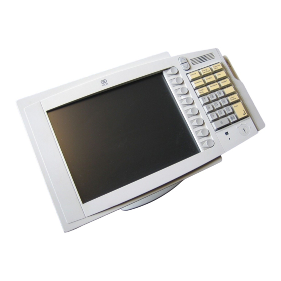
Page 35: Operator Display
Chapter 1: Product Overview 1-21 Operator Display 18427 The 7455 is available with either a 12.1" TFT (active matrix) or a 12.1" DSTN (passive matrix) LCD. DSTN LCD panels require a contrast adjustment for optimal viewing. Contrast control is set by software, using a digital potentiometer on the Processor Board. -
Page 36: Lcd Backlight Inverter Module
DynaKey The DynaKey operator input device is integrated in the 7455 Retail Terminal and is the main source of input from the operator. The DynaKey interface offers a standard 10-key setup surrounded by programmable buttons for any variety of functions. -
Page 37: Ncr 7455 Remote Displays
The NCR 5972 2x20 VFD supports two lines of twenty characters. NCR 5973 International VFD Customer Display The NCR 5973 VFD (Vacuum Fluorescent Display) is an optional display device for the 7455 Retail Terminal. The VFD is available in models that have a combination of: •... -
Page 38: 16" High Post Mount
1-24 Chapter 1: Product Overview Table Top Mount 12271 16" High Post Mount 17198... -
Page 39: Features
Chapter 1: Product Overview 1-25 Features Magnetic Stripe Reader A single, 3-track, analog Magnetic Stripe Reader (MSR) is available as a feature, supporting ISO and JIS format cards. When the MSR is not desired, a filler piece for the MSR section is included to make the unit appear uniform. -
Page 40: Printer Options
The sections that follow provide an illustration and brief description of each printer. Note: The 7455 power supply does not provide a 24V line for printers. Therefore, any printer connected to the 7455 requires a separate power supply. -
Page 41: 7158 Printer
Chapter 1: Product Overview 1-27 7158 Printer The 7158 Printer is an extremely fast, quiet, and reliable point-of-sale device. It consists of two specialized printers in one compact package: a thermal printer on top that prints receipts, and an impact slip printer in front to print on forms and checks that you insert. -
Page 42: 7194 Printer
1-28 Chapter 1: Product Overview 7194 Printer The 7194 Printer is a high speed, high-resolution printer, capable of both text and graphics printing. It offers direct thermal printing in a receipt station. The 7194 can connect through a USB port or a serial port. -
Page 43: Other Integrated Devices And Indicators
Chapter 1: Product Overview 1-29 Other Integrated Devices and Indicators Hard Disk Drive A 2.5" IDE Hard Disk is included. The drive is the standard type that is used by notebook PCs. The hard drive can be upgraded or replaced through a special service access panel on the back of the unit. -
Page 44: Internal Speaker
1-30 Chapter 1: Product Overview Internal Speaker The Internal Speaker is connected to the PC speaker output of the system chipset, not to the audio subsystem. It is connected to the Processor Board via a harness, and is mounted inside the Processor Board enclosure. -
Page 45: Power/Status Led
Chapter 1: Product Overview 1-31 A photodiode mounted behind the front bezel of the unit senses ambient light levels. The photodiode resides on a small circuit board (the Motion Sensor Board). A harness connects the Motion Sensor Board to the amplifier and motion sensing logic on the Processor Board. -
Page 46: Power Supply
Note: The power available to peripherals depends on the configuration of the base terminal and the power required by the peripherals. Careful consideration of the power demands of the system should be taken to ensure it does not exceed that provided by the 7455 power supply. - Page 47 Chapter 1: Product Overview 1-33 The following table notes the power requirements of the most common peripherals. Item Description 3.3VDC 5.0VDC 12VDC Requires Ext. Power Source Power Supply (95 Watts 497-0415258) 4.10 9.30 2.90 Summa POS Motherboard with CPU, & 2.00 3.00 0.04 up to 256MB RAM Personality Board...
- Page 48 1-34 Chapter 1: Product Overview Item Description 3.3VDC 5.0VDC 12VDC Requires Ext. Power Source Power available for Peripherals 1.61 5.35 1.43 Hard Disk Drive 2.5" 0.50 CD-ROM(TEAC, 24X) 006-8603220 C 1.00 Keyboards 0.20 Display 4x20 VFD Powered from Parallel Port 1.00 Display 4x20 VFD Powered from Serial Port 0.45...
-
Page 49: Usb Rs-232 Port Server
Chapter 1: Product Overview 1-35 USB RS-232 Port Server The USB RS-232 Port Server is an intelligent, stackable expansion module that connects to the terminal USB port, providing high-speed RS-232 serial ports. USB Port RS-232 Ports 16944... - Page 50 1-36 Chapter 1: Product Overview...
-
Page 51: Introduction
Hardware Installation Chapter 2: Introduction The terminal is fully assembled at the factory. This chapter explains the mounting options and how to connect optional hardware components to the terminal. Installation Summary The terminal should be removed from the shipping packaging and visual checks made to verify the correct hardware configuration. -
Page 52: Installation Restrictions
Chapter 2: Hardware Installation Installation Restrictions • Before installing the terminal, read and follow the guidelines in the NCR 7455 Retail Terminal Site Preparation Guide (B005-0000-1286) and the NCR Workstation and Peripheral AC Wiring Guide (BST0-2115-53). • Install the terminal near an electrical outlet that is easily accessible. -
Page 53: Connecting The Cables
Chapter 2: Hardware Installation Connecting the Cables The cable connectors are located on the underside of the unit, under a cable cover. Accessing the Cable Connectors 1. Tilt the display to access the cable connectors. 2. Loosen the thumbscrews (2) that secures the Cable Cover and remove the cover. -
Page 54: Routing The Cables
Chapter 2: Hardware Installation Routing the Cables The 7455 contains three anchors to secure cables to the base of the unit using a cable tie wrap. Remove the power supply cover from the base of the unit, which is secured by two screws on the bottom rear. Use a tie wrap to secure the Ethernet cable to one of the provided molded cable tie holders on the base. -
Page 55: Identifying The Cable Connectors
Chapter 2: Hardware Installation Identifying the Cable Connectors The following illustration identifies each of the cable connectors. Refer to the sections following the illustration for specific instructions on installing each peripheral. After installing the peripheral and LAN cables, replace the cable cover and tighten the thumbscrew. Note: 12VDC output on the powered RS-232 ports. -
Page 56: Installing Peripherals
Chapter 2: Hardware Installation Installing Peripherals 7158 Printer 1. Connect the Printer Interface Cable to the RS-232 Connector on the printer, located on the underside of the printer. Cash Drawer Power Connector Printer Connector RS232 17333 2. Connect the other end of the printer cable to a USB port or one of the RS-232 ports (non-powered) on the terminal. -
Page 57: 7166 Printer
Chapter 2: Hardware Installation 7166 Printer 1. Connect the Printer Interface Cable to the RS-232 Connector on the printer, located on the underside of the printer. Printer Connector RS232 Cash Drawer Power Connector 17332 2. Connect the other end of the printer cable to one of the RS-232 ports (non-powered) on the terminal. -
Page 58: 7194 Printer
Chapter 2: Hardware Installation 7194 Printer 1. Connect the Printer Interface Cable to the RS-232 Connector on the printer, located on the underside of the printer. Cash Drawer Connector Power Connector RS-232 Connector 16632 2. Connect the other end of the printer cable to a USB port or one of the RS-232 (non-powered) ports on the terminal. -
Page 59: 7196 Printer
Chapter 2: Hardware Installation 7196 Printer 1. Connect the Printer Interface Cable to the RS-232 Connector on the printer, located on the underside of the printer. Printer Connector RS232 Cash Drawer Power Connector 17331 2. Connect the other end of the printer cable to one of the RS-232 (non-powered) ports on the terminal. -
Page 60: 7162 Printer
2-10 Chapter 2: Hardware Installation 7162 Printer 1. Connect the Printer Interface Cable to the RS-232 Connector on the printer, located on the underside of the printer. Cash Drawer Kickout Connectors RS232 Connector Power Connector 15223 2. Connect the other end of the printer cable to one of the RS-232 ports (non-powered) on the terminal. -
Page 61: Installing A Remote Customer Display
Chapter 2: Hardware Installation 2-11 Installing a Remote Customer Display The terminal supports three high-post remote customer displays. The mounting configuration is the same and appearance is similar: • 7448 Remote Customer Display (4x20 characters, VFD) • 5972-1000 Remote Customer Display (2x20 characters, VFD) •... - Page 62 2-12 Chapter 2: Hardware Installation 3. Secure the Mounting Plate with 4 screws provided. Mounting Plate 4 Holes 0.40 mm (0.16 in.) Diameter 76 mm (3 in.) 16671 4. Connect the Display Cable to the Customer Display port on the terminal.
-
Page 63: 5972-1000 Remote Customer Display
Chapter 2: Hardware Installation 2-13 5972-1000 Remote Customer Display 16257 1. Place the Display Mount on the desired surface within 4 meters (13 feet) of the host terminal. 2. Secure the Mounting Plate with 4 screws provided. Mounting Plate 4 Holes 0.40 mm (0.16 in.) Diameter... - Page 64 2-14 Chapter 2: Hardware Installation 3. Connect the 5972 Display Cable to the Parallel I/F Adapter Cable. 4. Connect the Parallel I/F Adapter Cable to the Customer Display port on the terminal. Customer Display 18368 5. Connect the 5972 Display Cable Power Pigtail to the Power Brick. 6.
-
Page 65: 5973 International Vfd Customer Display
Chapter 2: Hardware Installation 2-15 5973 International VFD Customer Display (4) Screws 14528 1. Place the Display Mount on the desired surface within 4 meters (13 feet) of the host terminal. 2. Determine if the cable should be routed down through the mounting surface or if it should be run on top of the surface. -
Page 66: Installing A Cash Drawer
2-16 Chapter 2: Hardware Installation 4. Connect the 5973 Parallel Cable to the Customer Display port on the terminal. A parallel adapter cable is required. Customer Display 18368 Installing a Cash Drawer 1. Place the cash drawer in the desired location, within cable length of the terminal. - Page 67 Chapter 2: Hardware Installation 2-17 2. Connect the cash drawer cable to the terminal cash drawer connector. Cash Drawer 18370 Note: The Cash Drawer can optionally be connected to the printer.
-
Page 68: Installing A Second Cash Drawer
2-18 Chapter 2: Hardware Installation Installing a Second Cash Drawer The terminal supports a 2-drawer configuration with a Y cable (1416-C372-0006). 1. Place the cash drawer in the desired location, within cable length of the terminal. 2. Connect the Y cable to the terminal cash drawer connector. 18371... -
Page 69: Finalizing The Installation
Chapter 2: Hardware Installation 2-19 Finalizing the Installation After the hardware installation has been completed, the terminal can be powered up to finalize the installation. The operating system, along with platform modifications, is pre-installed. The following sections list the steps involved to complete the system installation for each of the Gold Disk operating systems. -
Page 70: Completing The Os Installation (Windows 98)
2-20 Chapter 2: Hardware Installation 4. Enter the Computer Name for the client. 5. Enter the Administrator’s Account Password (optional). 6. When prompted, press Finish to reboot the client. 7. Log in when prompted. 8. If you have a touch screen equipped unit, open the Control Panel and run the MicroTouch screen calibration. -
Page 71: Guidelines For Calibrating The Touch Screen (If Equipped)
Chapter 2: Hardware Installation 2-21 Guidelines for Calibrating the Touch Screen (If Equipped) The following guidelines should be observed for calibrating the touch screen. • Calibration should be done at time of installation. • Recalibrate the touch screen when the system is installed at its final location. -
Page 72: Summary
2-22 Chapter 2: Hardware Installation • If cursor is not stable, or false touches are suspected, run the Noise Check Utility from the Touchware Control Panel (Windows) or from the Microcal (DOS) program. Choose the recommended frequency (the one with the lowest noise level). This should also be done if the touch screen is still not calibrated after one attempt to recalibrate it. -
Page 73: Out-Of-Box Failures
The customer is responsible for restoring operating system software and/or customer-specific data onto replacement disks sent to repair a failed or damaged disk in the field. NCR provides recovery tools for the operating system and platform software. - Page 74 2-24 Chapter 2: Hardware Installation...
-
Page 75: Introduction
Setup Chapter 3: Introduction This chapter describes how to configure the BIOS CMOS options. Note: The Setup Menus in this chapter reference NCR 7401/7452/7453/7454/7455 BIOS Version 2.1.2.0 ® (Pentium III/Celeron). Entering Setup Using a Keyboard 1. Apply power to the terminal. -
Page 76: Entering Setup Without A Keyboard (On Units With Touch-Screen)
Chapter 3: Setup Entering Setup Without a Keyboard (on units with Touch- Screen) 1. Apply power to the terminal. 2. Calibrate the touch screen. a. When the screen prompt that says Touch the screen two times to enter Setup appears, touch the screen three times. This causes the system to bypass the BIOS Setup and go directly to the Touch Screen Calibration Setup. -
Page 77: How To Select Menu Options
Chapter 3: Setup How to Select Menu Options The following keyboard controls are used to select the various menu options and to make changes to their values. • Use the arrow keys to select (highlight) options and menu screens. • Use the + and - (or F5 and F6) keys to change field values. -
Page 78: Setup Menus
Chapter 3: Setup Setup Menus Main Menu P h o e n i x B I O S S e t u p U t i l i t y Main Main Advanced Security Power Boot Exit System Time: [10:54:34] Item Specific Help System Date: [05/25/2000]... -
Page 79: Legacy Diskette
Chapter 3: Setup Legacy Diskette The terminal does not have a flex disk drive. Therefore, this option is unused, even though Setup defaults to 1.44 MB, 3 ½". Primary Master After installing a new hard drive, the system should automatically detect the drive. -
Page 80: Advanced Menu
Chapter 3: Setup Advanced Menu P h o e n i x B I O S S e t u p U t i l i t y System Time: [12:34:00] Item Specific Help Advanced System Date: Main Advanced [02/29/1997] Security Power Boot... -
Page 81: Cache Memory
Chapter 3: Setup Cache Memory This option configures the specified block of memory. Note: Note: Cache memory must be present on the Processor Board to use this option. 1. Move the cursor to Cache Memory and press Enter. The following submenu displays. - Page 82 Chapter 3: Setup Cache System BIOS area Use this option to control caching of the system BIOS area. 1. Move the cursor to Cache System BIOS area and press Enter. 2. Select the desired setting from the drop-down menu. uncached Write Protect Cache Video BIOS area Use this option to control caching of the video BIOS area.
-
Page 83: I/O Device Configuration
Chapter 3: Setup I/O Device Configuration The I/O Device Configuration option is used to configure peripheral devices. Move the cursor to I/O Device Configuration and press Enter to access the following submenu. P h o e n i x B I O S S e t u p U t i l i t y I/O Device Configuration Item Specific Help Main... - Page 84 3-10 Chapter 3: Setup Serial Port x Use these options to configure the serial ports (A/B/C/D). 1. Move the cursor to Serial Port x and press Enter. 2. Select the desired setting from the drop-down menu. Disabled Enabled Auto • Disabled –...
- Page 85 Chapter 3: Setup 3-11 Parallel Port Use this option to configure the parallel port. 1. Move the cursor to Parallel Port and press Enter. 2. Select the desired setting from the drop-down menu. Disabled Enabled Auto • Disabled – no configuration •...
- Page 86 3-12 Chapter 3: Setup Fdc On Lpt Use this option to enable the primary floppy on the parallel port. 1. Move the cursor to Fdc On Lpt and press Enter. 2. Select the desired setting from the drop-down menu. Disabled Enabled Floppy Disk Controller This option configures the Floppy Disk Controller.
- Page 87 Chapter 3: Setup 3-13 Base I/O Address (Port C) Use this option to set the base I/O address for serial port C. 1. Move the cursor to Base I/O Address and press Enter. 2. Select the desired setting from the drop-down menu. Interrupt (Port C/D) This option sets the interrupt for serial port C/D.
- Page 88 3-14 Chapter 3: Setup Base I/O Address (Port D) Use this option to set the base I/O address for serial port D. 1. Move the cursor to Base I/O Address and press Enter. 2. Select the desired setting from the drop-down menu. Mode (Port D) Use this option to configure the COM D communication mode.
- Page 89 Chapter 3: Setup 3-15 Disk-On-Chip Address Use this option to select the memory address range used for the DiskOnChip. 1. Move the cursor to Disk-On-Chip and press Enter. 2. Select the desired setting from the drop-down menu. Disabled CC00-CDFF CE00-CFFF D000-D1FF MSR Address This option selects the memory address range used by the Magnetic...
-
Page 90: System Monitors
3-16 Chapter 3: Setup MSR Interrupt This option selects the interrupt used by the Magnetic Stripe Reader. 1. Move the cursor to MSR Interrupt and press Enter. 2. Select the desired setting from the drop-down menu. Disabled System Monitors 1. Move the cursor to the System Monitors option. 2. -
Page 91: Multiple Rom Menu
Chapter 3: Setup 3-17 Multiple ROM Menu Move the cursor to Multiple ROM Menu and press Enter. The items on this submenu are used to load/unload specific ROMs in the next boot. 1. Move the cursor to the appropriate Selectable ROM x option and press Enter. - Page 92 3-18 Chapter 3: Setup Large Disk Access Mode 1. Move the cursor to Large Disk Access Mode and press Enter. 2. Select the desired setting from the drop-down menu. Other • Select DOS for Windows NT O/S. • ® ™ ®...
-
Page 93: Advanced Chipset Control
Chapter 3: Setup 3-19 Advanced Chipset Control Move the cursor to Advanced Chipset Control and press Enter to access the following submenu. P h o e n i x B I O S S e t u p U t i l i t y Exit Submenu Main Advanced Chipset Control... - Page 94 3-20 Chapter 3: Setup Enable Memory Gap This option frees address space for use with an option card. 1. Move the cursor to Enable Memory Gap and press Enter. 2. Select the desired setting from the drop-down menu. Disabled Conventional Extended •...
- Page 95 Chapter 3: Setup 3-21 SERR Signal Condition This option selects the ECC error conditions that SERR# asserts. 1. Move the cursor to SERR Signal Condition and press Enter. 2. Select the desired setting from the drop-down menu. None Single bit Multiple bit Both Default Primary Video Adapter...
- Page 96 3-22 Chapter 3: Setup PCI/PNP UMB Resource Exclusion This option reserves specific memory regions for use by legacy devices. 1. Move the cursor to PCI/PNP UMB Resource Exclusion and press Enter. 2. Select the appropriate memory block from the list, C800-CBFF through DC00-DFFF, and press Enter.
-
Page 97: Boot-Time Diagnostic Screen
Chapter 3: Setup 3-23 Boot-Time Diagnostic Screen This option displays the diagnostic screen during boot. 1. Move the cursor to Boot-Time Diagnostic Screen and press Enter. 2. Select the desired setting from the drop-down menu. Disabled Enabled Note: If the Boot-Time Diagnostic Screen is disabled, you will instead see the logo of the POST results. -
Page 98: Security Menu Options
3-24 Chapter 3: Setup Boot menu retry Use this option to configure boot menu behavior. 1. Move the cursor to Boot menu retry and press Enter. 2. Select the desired setting from the drop-down menu. Keyboard Auto • Keyboard – user must press a key before POST retries booting from the devices in the boot menu •... -
Page 99: Set Supervisor/User Password
Chapter 3: Setup 3-25 Set Supervisor/User Password The Supervisor Password controls access to the setup utility. The User Password controls access to the system at boot. [Set] indicates that a password is present. [Clear] indicates that a password is not present. To enter a password, follow these steps: Note: The User Password cannot be set until after the Supervisor Password is set. -
Page 100: Fixed Disk Boot Sector
3-26 Chapter 3: Setup Fixed Disk Boot Sector When write protect is selected, the boot sector on the hard disk is write-protected against viruses. 1. Move the cursor to Fixed Disk Boot Sector and press Enter. 2. Select the desired setting from the drop-down menu. Normal Write Protect Password on Boot... -
Page 101: Power Menu Options
Chapter 3: Setup 3-27 Power Menu Options System Time: [12:34:00] Item Specific Help P h o e n i x B I O S S e t u p U t i l i t y System Date: [02/29/1997] Power Main Advanced Security... - Page 102 3-28 Chapter 3: Setup Customized Mode The Customized Mode permits user-defined settings. 1. Move the cursor to Standby Timeout and press Enter. Standby Timeout sets the amount of time the system needs to be in Idle Mode before entering Standby mode. Standby mode turns off various devices in the system, including the screen, until you start the computer again.
-
Page 103: Ide Drive X Monitoring
Chapter 3: Setup 3-29 IDE Drive x Monitoring This option enables IDE device activity to keep the system awake. 1. Move the cursor to IDE Drive x Monitoring and press Enter. 2. Select the desired setting from the drop-down menu. Disabled Enabled PCI Bus Monitoring... -
Page 104: Boot Menu Options
3-30 Chapter 3: Setup Boot Menu Options P h o e n i x B I O S S e t u p U t i l i t y Boot Main Advanced Security Power Boot Exit Item Specific Help Hard Drive ATAPI CD-Rom Drive Removable Devices... -
Page 105: Exit Menu Options
Chapter 3: Setup 3-31 Exit Menu Options P h o e n i x B I O S S e t u p U t i l i t y Main Advanced Security Power Boot Exit Exit Saving Changes Item Specific Help Exit Discarding Changes Load Setup Defaults Discard Changes... -
Page 106: Memory Map
48 K BIOS Reserved (currently available as UMB) D0000-DFFFF 64 K Available HI DOS memory CE000-CFFFF Flash Disk (optional) CC000-CDFFF NCR Trigantor MSR (optional) C8000-CBFFF 16 K Available HI DOS memory C0000-C9FFF 40 K On-board video BIOS A0000-BFFFF 128 K... -
Page 107: Bios Default Values
Chapter 3: Setup 3-33 BIOS Default Values Following are the BIOS default values for the workstation. Main Values Note: An asterisk (*) indicates a variable value based on system specification, etc. System Time System Date Legacy Diskette A: Disabled Legacy Diskette B: Disabled Primary Master 6007 MB... -
Page 108: Advanced Values
3-34 Chapter 3: Setup Secondary Master None Type Auto Multi-Sector Transfers Disabled LBA Mode Control Disabled 32 Bit I/O Disabled Transfer Mode FPIO 4/DMA 2 Ultra DMA Mode Mode 2 Secondary Slave None Type Auto Multi-Sector Transfers Disabled LBA Mode Control Disabled 32 Bit I/O Disabled... - Page 109 Chapter 3: Setup 3-35 Cache Extended Memory Write Back Cache A000-AFFF Disabled Cache B000-BFFF Disabled Cache C800-CBFF Disabled Cache CC00-CFFF Disabled Cache D000-D3FF Disabled Cache D400-D7FF Disabled Cache D800-DBFF Disabled Cache DC00-DFFF Disabled Cache E000-E3FF Write Protect Cache E400-E7FF Write Protect Cache E400-E7FF Write Protect Cache EC00-EFFF...
- Page 110 3-36 Chapter 3: Setup Interrupt IRQ 11 Scanner Power Auto Serial Port D Enabled Base I/O Address Interrupt IRQ 11 Mode RS-232 Disk-On-Chip Address CE00 - CFFF MSR Address CC00 - CDFF MSR Interrupt System Monitors +12 V Status + 2.5 V Status + 5 V Status CPU Temperature System Temperature...
- Page 111 Chapter 3: Setup 3-37 WaveLAN PXE Rom Disabled Selectable ROM 6 Disabled Selectable ROM 7 Disabled Selectable ROM 8 Disabled Selectable ROM 9 Disabled Selectable ROM 10 Disabled Selectable ROM 11 Disabled Selectable ROM 12 Disabled Selectable ROM 13 Disabled Selectable ROM 14 Disabled Selectable ROM 15...
-
Page 112: Security Values
3-38 Chapter 3: Setup DC00 - DFFF Available PCI/PNP IRQ Resource Exclusion IRQ 3 Available IRQ 4 Available IRQ 5 Available IRQ 7 Available IRQ 9 Available IRQ 10 Available IRQ 11 Available PCI IRQ line 1 Auto-Select PCI IRQ line 2 Auto-Select PCI IRQ line 3 Auto-Select... -
Page 113: Power Values
Chapter 3: Setup 3-39 Power Values Disabled Power Savings Standby Timeout Auto Suspend Timeout Disabled IDE Drive 0 Monitoring Disabled IDE Drive 1 Monitoring Disabled IDE Drive 2 Monitoring Disabled IDE Drive 3 Monitoring Disabled PCI Bus Monitoring Exit Values Press ENTER Exit Saving Changes Press ENTER... - Page 114 3-40 Chapter 3: Setup...
-
Page 115: Chapter 4: Operating System Recovery
CD-ROM media. The drivers that are necessary to run the CD-ROM are temporarily installed during boot. Prerequisites The following are required on the 7455 in order to perform a BIOS update using a CD. • Bootable CD-ROM drive (internal or external) •... -
Page 116: Updating Procedures
2. Connect the opposite end of the CD-ROM cable (end with the power connector pigtail) to the CD-ROM drive parallel connector. Note: The parallel port on the 7455 is the Customer Display port. Therefore, if your terminal is configured with a Customer Display, you must temporarily disconnect it in order to use the CD-ROM drive. - Page 117 Chapter 4: Operating System Recovery 7. Enter whether or not you want to perform Disk verification. (Answering Yes takes twice as long, but is recommended.) If Yes is selected: • ® The Ghost software verifies write operations and handles bad FAT clusters.
-
Page 118: Completing The Os Installation (Windows Nt)
Chapter 4: Operating System Recovery Completing the OS Installation (Windows NT) The system automatically reboots when the image recovery is complete and starts the software installation. This installation also installs most of the additional software and drivers that are included in the disk image. -
Page 119: Completing The Os Installation (Windows 2000)
Chapter 4: Operating System Recovery Completing the OS Installation (Windows 2000) The system automatically reboots when the image recovery is complete and starts the software installation. This installation also installs most of the additional software and drivers that are included in the disk image. -
Page 120: Gold Disk Contents
If you are using the information in this section to build your own operating system image and not using NCR’s provided OS Recovery image as a base image, then we recommend that all installed drivers be placed in a similar c:\install directory for support. -
Page 121: Ncr 7455 Nt Operating System Recovery Software
Chapter 4: Operating System Recovery NCR 7455 NT Operating System Recovery Software (LPIN: D370-0474-0100) • Installed NT-Workstation 4.0 w/SP4a • Added SP6a directory with all associated install files • IE5 installed • MicroTouch 5.4 installed, patch added (mtsi8042.sys) • Bus Master installed •... -
Page 122: Ncr 7455 Win98 Os Recovery Software
Windows Installer installed • Changed APM monitor shutoff to NEVER • Added SMI Control Panel • Userinfo.exe added to Startup (User info input) • Enabled 3D Sterio Enhancement NCR 7455 DOS Operating System Recovery Software (LPIN: D370-0518-0100) • ® Install MS-DOS 6.22... -
Page 123: Os Recovery From A Larger Disk Image
Chapter 4: Operating System Recovery OS Recovery from a Larger Disk Image The following procedure should be used to restore an Operating System when the destination disk is smaller than the source image (e.g., OS Recovery was made on a 10 GB source disk, but is being recovered on a 6 GB drive). - Page 124 4-10 Chapter 4: Operating System Recovery 10. The directory that Ghost is now looking in should be Z: (if not, switch to Z). Select the File name to load image from file (nnnnnnn.gho) and press Enter. 11. Select the Local Destination Drive and press Enter. 12.
-
Page 125: Chapter 5: Bios Updating Procedures
BIOS Update procedure, you can use the method discussed later in this chapter in the BIOS Crisis Recovery section to recover the BIOS. Prerequisites The following are required on the 7455 to perform a BIOS update using a CD. • Bootable CD-ROM drive (internal or external) •... -
Page 126: Updating Procedures
Parallel Connector Power Connector Parallel Connector 18614 Note: The parallel port on the 7455 is the Customer Display port. Therefore, if your terminal is configured with a Customer Display, you must temporarily disconnect it in order to use the CD-ROM drive. - Page 127 Chapter 5: BIOS Updating Procedures 3. Apply power to the terminal so the CD-ROM drive can be opened. 4. Insert the BIOS update CD. NCR 7455 BIOS and BIOS Update Software LPIN: A3D-0022 5. Boot the client terminal. You should see a message during boot indicating that the CD-ROM has been recognized similar to the one below: Micro Solutions BACKPACK CD-ROM v0.3...
- Page 128 Chapter 5: BIOS Updating Procedures 11. From the Advanced menu, select the Reset Configuration Data and then use the space bar to change the selection to Yes. 12. If you used the Backpack External CD-ROM drive, enter Setup when the terminal reboots and reset the Parallel CD-ROM Boot Disabled 13.
-
Page 129: Bios Crisis Recovery
Parallel Dongle Forces BIOS recovery 497-0414184 POS Connector Board 7455 parallel port (not required if already present) Required Software Acquire the following software from NCR. NCR 74xx BIOS and BIOS Update Software LPIN: A370-0022-0100, Release 3.0 or later P/N: 497-0424310... -
Page 130: Recovery Procedures
Com1 Parallel Port 19505 Note: The parallel connector on the 7455 terminal is used for the Customer Display. If the terminal is equipped with a Customer Display you must temporarily disconnect the display cable. 2. Connect the two machines with the RS-232 cable. Use COM Port 1 on both machines. - Page 131 6. Apply power to the terminal. 7. On the PC, change directory to the CD-ROM drive. E: [Enter] 8. Enter the update command: EMBflash [Enter] 9. Select the number for the 7455 terminal from the menu list: 1) 7454 2) 7401 3) 7452 4) 7453...
- Page 132 Chapter 5: BIOS Updating Procedures A blue screen displays as the program runs, showing the program progress, followed by a green screen, indicating a successful load. PhoenixPhlash Status Flash memory has been successfully programmed PRESS ANY KEY TO EXIT 19502 The Class/Model/Serial # information is deleted using the Crisis Recovery procedure.
-
Page 133: Cable/Connector Pin-Out Information
Chapter 5: BIOS Updating Procedures Cable/Connector Pin-Out Information Parallel Dongle 25-Pin D-shell Receptacle (Viewed from wiring side) 19513 RS-232 Cable 9-Pin 9-Pin D-shell D-shell Receptacle Receptacle 19512... - Page 134 5-10 Chapter 5: BIOS Updating Procedures...
-
Page 135: Appendix A: Cables
Cables Appendix A: 7455 Cables Corporate ID Part Number Description 1416-C321-0030 006-8601012 Cordset-United Kingdmn Plug with straight ‘BM’ power Cordset-Australian cable with 1416-C322-0030 006-8601019 straight ‘BM’ power 1416-C323-0030 006-8601010 Cordset-International cable with straight ‘BM’ power 1416-C325-0030 006-1009037 Cord set – Power US... - Page 136 Appendix A: Cables Corporate ID Part Number Description 1416-C570-0001 497-0417000 Mouse adapter cable 1416-C628-1000 497-0418248 Cable-VFD I/F with power Cable-2x20 VFD RS-232 I/F with 1416-C629-1000 497-0418249 power 1416-C634-4000 497-0418406 Cable-EFT, w/power, 4M 1416-C672-0030 497-0420456 Cable-Ethernet 10/100BaseT 1416-C679-0009 497-0420834 Assy-Cable, VFD W/Autodect (0.9M)
-
Page 137: Appendix B: Feature Kits
Below is a comprehensive list of the optional hardware Feature Kits that can be installed in the customer environment. Kit installation instructions (for those requiring instruction) are available on the Information Products web sites. • NCR Intranet: http://inforetail.atlantaga.ncr.com • Internet: http://www.info.ncr.com On the web sites, search for the kits by Title or Product ID (kit number). - Page 138 Appendix B: Feature Kits Kit Number Part Number Description 2330-K326 497-0412346 WaveLAN 2 - 2.4 GHz PCMCIA network card (Japan) 2330-K327 497-0412347 WaveLAN 2 - 2.4 GHz PCMCIA network card (Europe) WaveLAN 2 - 2.4 GHz PCMCIA network 2330-K328 497-0412348 card (France) 2330-K350 497-0412349...
- Page 139 Dual PCMCIA interface 7455-K561 497-0419973 Integrated low 4x20 customer display 7455-K562 497-0420836 Integrated post 4x20 customer display 7455-K728 497-0419970 Integrated CDROM 7455-K728 497-0420498 Kit-integrated CDROM (new version) 7455-K730 497-0419972 No CDROM cover 7455-K775 497-0423981 Kit – 7455 ESD upgrade for JIS MSR...
- Page 140 Appendix B: Feature Kits...
- Page 141 Index —A— —G— Advanced power management, 1-20 Graphics subsystem, 1-17 Audio, 1-12 —H— —B— Hard disk drive, 1-29 BIOS crisis recovery, 5-5 Hardware monitor, 1-12 BIOS Recovery Hardware options, 1-4 crisis recovery procedures, 5-5 Using CD-ROM, 5-1 —I— Integrated customer display —C—...
- Page 142 Index-2 —O— —S— Operating System Recovery Serial number, 1-2 Using CD-ROM, 4-1 Serial ports, 1-11 Operator display Setup Description, 1-21 Advanced menu, 3-6 Boot Menu Options, 3-30 Default factory settings, 3-3 —P— Eentering with a keyboard, 3-1 Entering without a keyboard, 3-2 PCI expansion header, 1-12 Exit Menu Options, 3-31 PCMCIA, 1-4, 1-10, 1-12, 1-32...
- Page 144 B005-0000-1285 January 2002 Printed on recycled paper...