Jøtul GF 500 DV IPI Installation And Operation Instructions Manual
Direct vent
Hide thumbs
Also See for GF 500 DV IPI:
- Installation and operation instructions manual (44 pages) ,
- Installation and operation manual (40 pages) ,
- Manual (4 pages)
Table of Contents
Advertisement
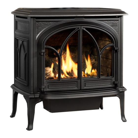
The
Portland
WARNING: If the information in these
instructions is not followed exactly, a fire
or explosion may result causing property
damage, personal injury or loss of life.
– Do not store or use gasoline or other
flammable vapors and liquids in the vicinity
of this or any other appliance.
– WHAT TO DO IF YOU SMELL GAS
• Do not try to light any appliance.
• Do not touch any electrical switch; do not
use any phone in your building.
• Immediately call your gas supplier from a
neighbor's phone. Follow the gas supplier's
instructions.
• If you cannot reach your gas supplier, call
the fire department.
– Installation and service must be performed
by a qualified installer, service agency or the
gas supplier.
– In the Commonwealth of Massachusetts,
a carbon monoxide (CO) detector shall be
installed in the same room as the appliance.
This appliance may be installed in an aftermarket,
permanently located, manufactured home or mobile
home, where not prohibited by local codes.
This appliance is only for use with the types of gas
indicated on the rating plate. A conversion kit is
supplied with the appliance.
INSTALLER: Leave this manual with the appliance.
CONSUMER: Retain this manual for future reference.
Installation and
Operation Instructions
ATTENTION : CES INSTRUCTIONS DOIVENT
DEMUERER AVEC LE PROPRIÉTERE D'UNE
MAISON.
AVERTISSEMENT: Assurez-vous de bien
suivreles instructions données dans cette
notice pour réduire auninimum le risque
d'incendie ou d'explosion ou pour éviter
tout dommage matériel, toute blessure ou la
mort.
– Ne pas entreposer ni utiliser d'essence ni
d'autres vapeurs ou liquides inflammables
dans le voisinage de cet appareil ou de tout
autre appareil.
– QUE FAIRE SI VOUS SENTEZ UNE ODEUR DE GAZ:
• Ne pas tenter d'allumer l'appareil.
• Ne touchez à aucum interrupteur.
Ne pas vous servir des téléphones se
trouvant dans le bâtiment où vous
trouvez.
• Appelez immédiatement votre
fournisseur de gaz depuis un voisin.
Suivez les instructions du fournisseur.
• Si vou ne pouvez rejoindre le
fournisseur de gaz, appelez le service des
incendies.
– L'installatione l'entretien doivent être
assurés par un installateur ou un service
d'entretien qualifié ou par le fournisseur
de gaz.
139636 GF 500 DV IPI 7/28/14
1
Advertisement
Table of Contents

Related Manuals for Jøtul GF 500 DV IPI


Summary of Contents for Jøtul GF 500 DV IPI
-
Page 1: Operation Instructions
139636 GF 500 DV IPI 7/28/14 Portland Installation and Operation Instructions WARNING: If the information in these ATTENTION : CES INSTRUCTIONS DOIVENT instructions is not followed exactly, a fire DEMUERER AVEC LE PROPRIÉTERE D’UNE or explosion may result causing property MAISON. -
Page 2: Service Tools
139636 GF 500 DV IPI 7/28/14 WARNING Installation Requirements for the Commonwealth of Massachusetts THIS PRODUCT MUST BE INSTALLED BY HOT GLASS WILL A LICENSED MASTER OR JOURNEYMAN PLUMBER OR GAS-FITTER WHEN CAUSE BURNS INSTALLED IN THE COMMONWEALTH OF DO NOT TOUCH GLASS MASSACHUSETTS. -
Page 3: Table Of Contents
139636 GF 500 DV IPI 7/28/14 Table of Contents Jøtul GF 500 DV IPI Service Tools ..........2 Portland Specifications ..........4 Initial Assembly ........5 Direct Vent Gas Heater Rear Exit Vent Conversion ....... 6 Manufactured and Distributed by: General Information ........ 7 Jøtul North America... -
Page 4: Specifications
765 mm 762 mm 25 7/8” 657 mm 22 1/2” 572 mm 6 1/2” 165 mm 16 3/4” 27 3/4” 425 mm 11 7/8” 704 mm 302 mm 21 1/4” 540 mm Figure 1. Dimensioned views, GF 500 DV IPI... -
Page 5: Initial Assembly
139636 GF 500 DV IPI 7/28/14 Initial Assembly Hardware Bag Contents • Fuel Conversion Kit - LP ........157693 • Rock Wool, 1 oz........... 157259 • Top Plate Insert (for Rear Exit applications) • 1.5v AA Batteries, 4 CAUTION: Enamelled parts may be damaged if handled without care. -
Page 6: Rear Exit Vent Conversion
139636 GF 500 DV IPI 7/28/14 Rear Exit Vent Conversion This stove is built in the top exit vent configuration. Follow the procedure below to convert the vent adaptor for a rear exit installation. 1. Use a 1/4” nut driver to remove four inner screw from around the exhaust collar. -
Page 7: General Information
139636 GF 500 DV IPI 7/28/14 General Information Safety Information Due to the high operating temperatures this appliance THIS HEATER MUST BE INSTALLED AND MAINTAINED should be located out of traffic and away from BY A QUALIFIED SERVICE AGENCY. -
Page 8: Installation Requirements
4) Traffic areas, furniture, draperies, etc. Minimum Clearances from the Stove to Combustibles: See figs. 8-12. The GF 500 DV IPI may be located on or near conven- Measured from: tional construction materials, however, proper clearance to combustibles must be maintained in order to provide Rear: 1 1/2”... -
Page 9: Mantel & Trim
139636 GF 500 DV IPI 7/28/14 Max. Mantel Depth 11.5” 9.5” 7.5” 5.5” Min. Mantel Depth 1” Max. Top Trim Depth Figure 8. Parallel Installation Clearances. 40 3/4 in. (1035 mm) 34 3/4 in. (883 mm) 39 1/4 in. (997 mm) 3 1/4 in. -
Page 10: Venting Requirements
Vent Restriction The GF 500 DV IPI is equipped with an Exhaust Restrictor The Jøtul GF 500 DV IPI gas stove may be installed with Plate which enables you to regulate the flow of exhaust a vertical or horizontal termination and must conform to gas. -
Page 11: Termination Matrix
139636 GF 500 DV IPI 7/28/14 FULL RESTRICTION RESTRICTION Figure 14. Use 1/4” socket driver to loosen the Exhaust Restrictor dial and adjust to the appropriate notch for your termination zone. 35 Ft. (10.67 m) 30 Ft. (9.14 m) TERMINATION APPROVED 25 Ft. -
Page 12: Vertical Termination
139636 GF 500 DV IPI 7/28/14 Vertical Vent Termination The Jøtul GF 500 DV IPI can be vertically vented through a ceiling or to a roof termination with the following guidelines: The termination should fall within the shaded areas of ... - Page 13 139636 GF 500 DV IPI 7/28/14 Max.12” 305 mm Co-linear Vent Installation The GF 500 DV IPI may be vented through a masonry or Class A prefabricated chimney using a Co-linear Flexible Vent system approved for use with a solid-fuel burning Figure 17.
-
Page 14: Horizontal Termination
4” Flex Pipe not included Support/Wall in kit The GF 500 DV IPI is approved for use with components Thimble Cover of Simpson DuraVent Chimney Kit 46DVA-KMC and 46DVA-KCT in a masonry chimney or a Kits 46DVA-KCA, 46DVA-KCB, and 46DVA-KCC for prefabricated solid fuel listed chimneys. - Page 15 139636 GF 500 DV IPI 7/28/14 Minimum 1/2” Foil-face Ceramic Insulation Blanket Required Snorkel Termination This appliance is approved only for 36 inch Snorkel termination. Not approved for use with a 14 inch Snorkel. The minimum horizontal run may be no less than 6”...
-
Page 16: Vent Terminal Clearances
139636 GF 500 DV IPI 7/28/14 Horizontal Termination Clearance Vent Terminal Air Supply Terminals Prohibited in this Area Figure 24. Vent Terminal Clearances - ANSI Z21.88-2009, CSA 2.33-2009, and National Fuel Gas Code. A = Clearance above grade, veranda, porch , deck, or balcony M = Clearance under veranda, porch, deck, or balcony: : 12 inches (30 cm) minimum. -
Page 17: Fuel Conversion
Fuel Conversion 1. Turn off gas supply to stove. The GF 500 DV IPI gas stove is shipped from the factory 2. Remove the stove Top Plate and Forward Top Shroud as equipped to burn NATURAL GAS only. If PROPANE gas is in Fig. - Page 18 139636 GF 500 DV IPI 7/28/14 7. CHANGE THE INTEGRATED DUAL-FUEL PILOT ORIFICE: Use a 1/4” socket driver to loosen two screws and lift the pilot shield out of way to access the pilot head base. See fig. 28. Pilot Shield Use the 7/16”...
- Page 19 BAFFLE COMMING OUT 139636 GF 500 DV IPI 7/28/14 Baffle Assembly REMOVE BAFFLE W PERFORA BAFFLE T Figure 31. Figure 32. Baffle Assembly location. Remove two 6 mm nuts to Pull the baffle plate down slightly, then swing the end detach it from the firebox.
-
Page 20: Gas Supply Connection
139636 GF 500 DV IPI 7/28/14 Gas Supply Connection Leak test: NOTE: If appropriate, install the optional forced air 1. Mix a 50-50 solution of water and dish blower before connecting the gas line, to prevent soap. clearance interference between the two. -
Page 21: Gas Pressure
Correct gas pressure is essential for efficient and The decreased atmospheric pressure of higher safe operation of the GF 500 DV IPI gas stove. It is altitudes affects heat value of gaseous fuels. Most important that the correct pressure is established gas suppliers derate the gas intended for use at at the time of the installation. -
Page 22: Optional Brick Panel Installation
139636 GF 500 DV IPI 7/28/14 Accessories Optional Wall Thermostat 750003 Use only a 750 millivolt DC two-wire circuit wall thermostat with this appliance. The thermostat should 1. Locate the retainer tabs in the upper corner of each be placed in the same room as the heater, typically 5 side of the firebox. -
Page 23: Premium Upgrade Kits
139636 GF 500 DV IPI 7/28/14 Premium Upgrade Kits Accent Lamp #157498 - NG Contents: Tools Required: #157499 - LP 1. Lamp Box Assembly w/ harness • 10 mm wrench Kit Contents: 2. Lens • Safety goggles 3. Gasket • Work gloves •... -
Page 24: Blower
139636 GF 500 DV IPI 7/28/14 Optional Variable Speed Blower KIT 157470 THIS BLOWER MUST BE ELECTRICALLY 1. Disconnect the power supply from the stove. GROUNDED IN ACCORDANCE WITH LO- CAL CODES OR, IN THE ABSENCE OF LOCAL 2. Orient the Blower Bracket (fig. 44 #2) as shown and... -
Page 25: Log Set Installation
See page 22 or the instruc- tions provided with that kit. The GF 500 DV IPI log set must be installed before operating the burner. The log set includes six log pieces, packaged inside the firebox. Place the logs inside the firebox as illustrated in figs. -
Page 26: System Check
139636 GF 500 DV IPI 7/28/14 System Check 1. PURGING THE GAS LINE: When lighting the appliance for the first time, it will take a few moments to clear the gas line of air. Once this purge is complete, the appliance will operate as described in the lighting instructions. -
Page 27: Flame Picture Adjustment
139636 GF 500 DV IPI 7/28/14 Flame Appearance / Air Shutter Adjustment The GF 500 DV IPI gas stove is shipped from the factory equipped to burn Natural gas and the air inlet shutters OPEN have been set to provide optimal combustion efficiency CLOSED under a variety of venting configurations. -
Page 28: Operation Guidelines
139636 GF 500 DV IPI 7/28/14 Operation Important Notes WARNING: Check the build date on the shipping crate READ AND UNDERSTAND ALL OPERATING label. If it has been more than 6 months INSTRUCTIONS BEFORE ATTEMPTING TO OPERATE since the build date, be prepared to replace THIS APPLIANCE. -
Page 29: Manual Operation
139636 GF 500 DV IPI 7/28/14 Manual Operation Familiarize yourself with the controls of the GF 500 DV IPI and WARNING: be sure that anyone else using the appliance is also familiar with the controls and operation procedures. Always follow the... -
Page 30: Remote Control
139636 GF 500 DV IPI 7/28/14 Proflame 2 Pilot Assembly Remote Control The pilot assembly consists of a pilot hood, electrode, and a flame sensor. The electrode sends a spark to the pilot hood which ignites the gas. The sensor is then engulfed... -
Page 31: Control Functions
139636 GF 500 DV IPI 7/28/14 Control Functions Initializing the System 1. Press the Controls Access Door to release its magnetic Pilot Mode catch and swing the panel down. Switch the Burner to OFF. See fig. 52, pg. 29. Set the stove switch to CPI mode for Proflame 2 remote control. - Page 32 139636 GF 500 DV IPI 7/28/14 Remote Transmitter Controls Temperature Indication Display With the transmitter in the OFF position, press the Thermostat Key and the Mode Key at the same time. The display screen will show the current room temperature cycling between Fahrenheit and Celsius indicators each time the keys are pressed simultaneously.
- Page 33 139636 GF 500 DV IPI 7/28/14 Room Thermostat (Transmitter Operation) The Remote Control can operate as a room thermostat. Room Temperature The thermostat can be set to a desired temperature to control the comfort level in a room. To activate this function, press the Thermostat Key. The ...
-
Page 34: Maintenance
FOR REPLACEMENT, USE ONLY JØTUL CERAMIC GLASS PN 225476. DO NOT USE ANY OTHER TYPE OF GLASS WITH THIS APPLIANCE. Your Jøtul GF 500 DV IPI components and its venting Glass Panel or Gasket Removal system should be inspected before use and at least annually by a qualified service technician. -
Page 35: Battery Replacement - Transmitter
SIT Pro ame Valve Split Flow Valve Battery Pack Four, 1.5v AA Main Burner Switch Main IFC Harness Auxiliary Burner Switch SIT Proflame 2 IFC Optional Accent Optional Blower 120VAC Power Lamp Figure 76. GF 500 DV IPI Proflame 2 Components... -
Page 36: Illustrated Parts Lists
139636 GF 500 DV IPI 7/28/14 GF 500 DV IPI Illustrated Parts Breakdown Figure 77. Exterior replacement parts. Cast Iron Parts Matte Black Brown Majolica No. Part No. Description Paint Enamel 225330 Door Magnet Top Plate 10464892 10464847 224909 Magnet Cap, Hi-temp Vinyl... - Page 37 139636 GF 500 DV IPI 7/28/14 Figure 78. GF 500 DV IPI Valve Assembly and IFC Components. No. Part No. Description No. Part No. Description 117917 Screw, #8 x 1/2” SL Blk Oxide 117922 Nut, Hex M4 DIN 934 plain...
- Page 38 139636 GF 500 DV IPI 7/28/14 Figure 79. GF 500 DV IPI Pilot and Burner components. No. Part No. Description 117917 Screw 8 x 12 1/2 SL Blk Oxide 225528 Exhaust Baffle Wing 225456 Exhaust Baffle 224931 Brick Panel Retainer...
-
Page 39: Accessory Listing
139636 GF 500 DV IPI 7/28/14 No. Part No. Description Figure 80. GF 500 DV IPI Accent Lamp Assembly No. Part No. Description Figure 81. 117967 Screw, Pan Head #7 x 3/8 PH Zinc GF 500 DV IPI Glass Assembly... -
Page 40: Mobile Home Requirements
139636 GF 500 DV IPI 7/28/14 Mobile Home Installation The GF 500 DV IPI can be installed for use in a mobile home in the U.S. and Canada provided: 1. The stove is secured to the floor of the mobile home. - Page 41 139636 GF 500 DV IPI 7/28/14 THIS PAGE IS INTENTIONALLY BLANK...
-
Page 42: Warranty Statement
139636 GF 500 DV IPI 7/28/14 This warranty does not cover the following: Jøtul Gas Product 1) Repair or replacement of parts that are subject to normal wear and tear during the warranty period or to parts that may require replacement Limited Lifetime Warranty in connection with normal maintenance. -
Page 43: Lighting Instructions
139636 GF 500 DV IPI 7/28/14 LIGHTING INSTRUCTIONS FOR YOUR SAFETY, READ BEFORE LIGHTING. WARNING: IF YOU DO NOT FOLLOW THESE INSTRUCTIONS EXACTLY, A FIRE OR EXPLOSION MAY RESULT CAUSING PROPERTY DAMAGE, PERSONAL INJURY, OR LOSS OF LIFE. A. This appliance is equipped with an ignition device which automatically lights the pilot. - Page 44 Please record the serial number in the space below. You may also wish to attach your purchase receipt to this page for future reference. MODEL NAME: Jøtul GF 500 DV IPI SERIAL NUMBER:_______________________________ DATE OF PURCHASE:____________________________ AUTHORIZED DEALER:__________________________...