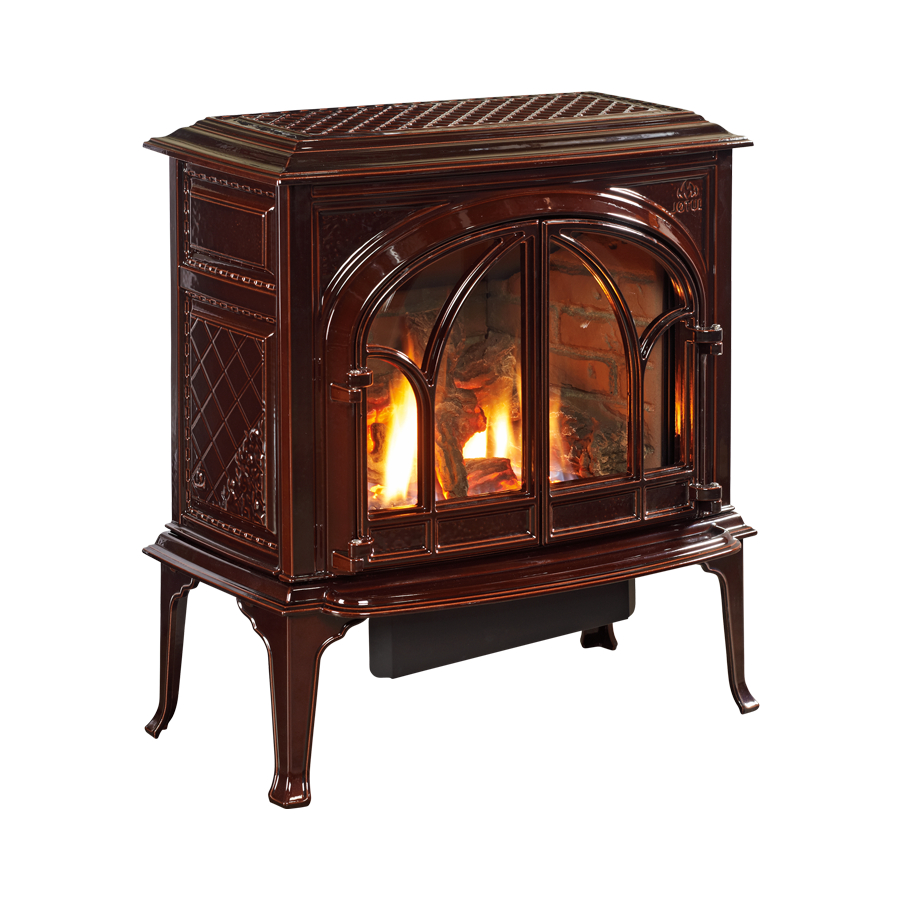
Jøtul GF 400 DV Sebago Installation And Operation Instructions Manual
Direct vent gas stove
Hide thumbs
Also See for GF 400 DV Sebago:
- Installation and operation instructions manual (32 pages) ,
- Installation and operation instructions manual (32 pages) ,
- Installation and operation instructions manual (40 pages)
Table of Contents
Advertisement
WARNING: If the information in these
instructions is not followed exactly, a fire
or explosion may result causing property
damage, personal injury or loss of life.
– Do not store or use gasoline or other
flammable vapors and liquids in the vicinity
of this or any other appliance.
– WHAT TO DO IF YOU SMELL GAS
• Do not try to light any appliance.
• Do not touch any electrical switch; do not
use any phone in your building.
• Immediately call your gas supplier from a
neighbor's phone. Follow the gas supplier's
instructions.
• If you cannot reach your gas supplier, call
the fire department.
– Installation and service must be performed
by a qualified installer, service agency or the
gas supplier.
– In the Commonwealth of Massachusetts,
a carbon monoxide (CO) detector shall be
installed in the same room as the appliance.
This appliance may be installed in an aftermarket,
permanently located, manufactured home or mobile
home, where not prohibited by local codes.
This appliance is only for use with the types of gas
indicated on the rating plate. A conversion kit is
supplied with the appliance.
INSTALLER: Leave this manual with the appliance.
CONSUMER: Retain this manual for future reference.
Installation and
Operation Instructions
ATTENTION : CES INSTRUCTIONS DOIVENT
DEMUERER AVEC LE PROPRIÉTERE D'UNE
MAISON.
AVERTISSEMENT: Assurez-vous de bien
suivreles instructions données dans cette
notice pour réduire auninimum le risque
d'incendie ou d'explosion ou pour éviter
tout dommage matériel, toute blessure ou la
mort.
– Ne pas entreposer ni utiliser d'essence ni
d'autres vapeurs ou liquides inflammables
dans le voisinage de cet appareil ou de tout
autre appareil.
– QUE FAIRE SI VOUS SENTEZ UNE ODEUR DE GAZ:
• Ne pas tenter d'allumer l'appareil.
• Ne touchez à aucum interrupteur. Ne
pas vous servir des téléphones se trouvant
dans le bâtiment où vous trouvez.
• Appelez immédiatement votre
fournisseur de gaz depuis un voisin.
Suivez les instructions du fournisseur.
• Si vou ne pouvez rejoindre le
fournisseur de gaz, appelez le service des
incendies.
– L'installatione l'entretien doivent être
assurés par un installateur ou un service
d'entretien qualifié ou par le fournisseur
de gaz.
137750_Rev_L 7.29.10
1
Advertisement
Table of Contents

Related Manuals for Jøtul GF 400 DV Sebago


Summary of Contents for Jøtul GF 400 DV Sebago
-
Page 1: Operation Instructions
137750_Rev_L 7.29.10 Installation and Operation Instructions WARNING: If the information in these ATTENTION : CES INSTRUCTIONS DOIVENT instructions is not followed exactly, a fire DEMUERER AVEC LE PROPRIÉTERE D’UNE or explosion may result causing property MAISON. damage, personal injury or loss of life. AVERTISSEMENT: Assurez-vous de bien suivreles instructions données dans cette –... -
Page 2: Service Tools
• Torx T-20 screwdriver to attach your purchase receipt to this page for future • Tin snips reference. MODEL NAME: Jøtul GF 400 DV Sebago Gas Stove We recommend that SERIAL NUMBER:_______________________________ our gas products be installed and serviced by... -
Page 3: Table Of Contents
137750_Rev_L 7.29.10 Table of Contents Jøtul GF 400 DV Sebago Direct Vent Gas Heater Service Tools ..........2 Specifications ..........4 Manufactured and Distributed by: General Information ........ 5 Jøtul AS Safety Information ........6 Fredrikstad, Norway Installation Requirements Jøtul North America Location ..........6... -
Page 4: Specifications
137750_Rev_L 7.29.10 Jøtul GF 400 DV Sebago Specifications Specifications 28 1/2” 724 mm Input Rates Natural Gas 32,000 BTU/hr. maximum input 18,000 BTU/hr. minimum input Propane 32,000 BTU/hr. maximum input 26 1/2” 673 mm 16,000 BTU/hr. minimum input Inlet Pressure: Natural Gas: 5.0 WC (1.24 kPa) 7.0 WC (1.74 kPa) -
Page 5: General Information
137750_Rev_L 7.29.10 General Information THIS HEATER MUST BE INSTALLED AND MAINTAINED BY A QUALIFIED SERVICE AGENCY. Glass Panel The installation and repair of this appliance must be Do not operate this appliance with the glass done by a qualified service person. Failure to properly front removed, cracked, or broken. -
Page 6: Safety Information
4) Traffic areas, furniture, draperies, etc. Children and adults should be alerted to the The GF 400 DV Sebago may be located on or near hazards of high surface temperatures and should conventional construction materials, however, proper stay away to avoid burns or clothing ignition. -
Page 7: Clearances
137750_Rev_L 7.29.10 Stove and Vent Clearance Minimum Clearances from the Vent Pipe to Combustibles: Requirements Horizontal Run: Off the top of the pipe 2” (51 mm) Minimum Clearances from the Stove Off the sides and bottom 1” (25 mm) to Combustibles: See figs. -
Page 8: Vent Requirements
137750_Rev_L 7.29.10 Venting Requirements Vent Restriction This appliance is equipped with Restrictor Plates which This appliance may be installed with a vertical or horizon- tal termination and must conform to the configuration enable you to regulate the flow of incoming combustion requirements described below. -
Page 9: Vertical Termination
137750_Rev_L 7.29.10 FRONT BACK Default Push the Fully Closed Pivot Pin into Factory the slot Setting is “D” Fully Open Figure 6. Adjusting the Air Inlet Restrictor plate - View is from the right side of the stove. Vertical Vent Termination This appliance can be vertically vented through a ceiling or to a roof termination with the following guidelines: The termination should fall within the shaded areas... - Page 10 137750_Rev_L 7.29.10 Vent Termination Zones - Natural Gas Vertical Termination for COLINEAR VENT 35 Ft. (10.67 m) Horizontal and Vertical Terminations for COAXIAL VENT 35 Ft. 35 Ft. (10.67 m) (10.67 m) 30 Ft. (9.14 m) Up to four 45° or two 90°...
- Page 11 137750_Rev_L 7.29.10 Vent Termination Zones - Propane Vertical Termination for COLINEAR VENT 35 Ft. (10.67 m) Horizontal and Vertical 35 Ft. Terminations for COAXIAL VENT (10.67 m) 30 Ft. (9.14 m) Up to four 45° or two 90° elbows permitted in 25 Ft.
-
Page 12: Co-Linear Termination
137750_Rev_L 7.29.10 High Wind Cap Exhaust Gas Co-linear Vent Installation Max. Co-linear Intake Air This appliance may be vented through a masonry or Class Height - 35 ft. (10.66 m) A prefabricated chimney using a Co-linear Flexible Vent Min. Co-linear system approved for use with a solid-fuel burning fire- Height - 10 ft. -
Page 13: Coaxial Chimney Conversion
137750_Rev_L 7.29.10 Vertical Termi- Masonry or Prefabricated Chimney Exhaust nation Cap Conversion Cap Adaptor- This appliance is approved for use with listed chimney included in Intake Air #934 Kit conversion kits from any of the manufacturers listed on page 8. These kits are for use in a masonry chimney or a prefabricated solid fuel listed chimney. -
Page 14: Horizontal Termination
137750_Rev_L 7.29.10 Horizontal Termination 12 in. (305 mm) Any horizontal termination must fall within the shaded portion of the vent window graph illustrated in figs. 9 or 11. For Snorkel Terminations, see below. Any horizontal termination except a snorkel termina- ... -
Page 15: Vent Terminal Clearances
137750_Rev_L 7.29.10 Horizontal Termination Clearance Figure 19. Vent Terminal Clearances - National Fuel Gas Code. Clearance above paved sidewalk or a paved driveway located A = Clearance above grade, veranda, porch , deck, or balcony on public property: 7 feet (2.1 m) min. : 12 inches (30 cm) minimum. -
Page 16: Mobile Home Installation
137750_Rev_L 7.29.10 Mobile Home Installation Fuel Conversion This appliance can be installed for use in a mobile home This appliance is shipped from the factory equipped to in the U.S. and Canada provided: burn NATURAL GAS only. If PROPANE gas is to be used as fuel, the appliance must first be converted for use with 1. - Page 17 137750_Rev_L 7.29.10 Fuel Conversion Procedure Refer to fig. 47, Illustrated Parts Breakdown, to identify part numbers below. Shutter OPEN CLOSED Turn off gas supply to stove. Wingnut Remove the stove Top Plate (41). Disengage the two Glass Frame Latches at the top of FRONT BACK the firebox.
-
Page 18: Gas Supply Connection
137750_Rev_L 7.29.10 NEVER USE AN OPEN FLAME TO CHECK FOR GAS LEAKS. 14. Remove the Regulator Tower, Gasket, white plastic disk, and Spring. Correct gas pressure is essential for efficient and safe operation of this appliance. Correct gas pres- 15. Install the new regulator: Be sure the new gasket is sure must be established at the time of installation. -
Page 19: Gas Pressure
1/2 psig (3.5 kPa). MANIFOLD PRESSURES (inches water column) Correct gas pressure is essential for efficient and safe operation of the GF 400 DV Sebago gas stove. It is im- NATURAL GAS portant that the correct pressure is established at the PROPANE 11.0... -
Page 20: Air Shutter Adjustment
137750_Rev_L 7.29.10 Flame Appearance / Air Shutter Optional Wall Thermostat or Adjustment Remote Control This appliance is shipped from the factory equipped to Use only a 750 millivolt DC two-wire circuit thermostat burn natural gas with the air shutter set half-open. with this appliance. -
Page 21: Log Set Installation
137750_Rev_L 7.29.10 Log Set Installation Figure 33. 220645 Install Rear Log NOTE: If appropriate, install the optional Antique Brick Panel Kit before assembling the logset. The logset must be installed before operating the burner. The logset includes five log pieces, packaged inside the firebox, and a quantity of ember stones packaged in the Miscellaneous Parts bag. -
Page 22: System Check
137750_Rev_L 7.29.10 System Check 1” (25mm) 1. PURGING THE GAS LINE: When lighting the appliance 3/8” for the first time, it will take a few moments to clear 1/8” (8mm) (3mm) Min. the gas line of air. Once this purge is complete, the Min. -
Page 23: Operation
137750_Rev_L 7.29.10 Operation Familiarize yourself with the controls of the GF 400 DV Sebago. Make sure that anyone else using the appliance is also familiar with the controls and operation procedures. Always follow the Lighting Instructions on the inside back cover of this manual and also located on the Rating Plate attached to the back of the stove. -
Page 24: Maintenance
137750_Rev_L 7.29.10 Maintenance FOR REPLACEMENT, USE ONLY JØTUL CERAMIC GLASS PANEL 220089. DO NOT USE ANY This appliance and its venting system should be inspect- OTHER TYPE OF GLASS WITH THIS APPLIANCE. ed before use and at least annually by a qualified service technician. -
Page 25: Optional Blower Installation
137750_Rev_L 7.29.10 Optional Blower # 156000 Connect the gas supply line to the stove, before installing the Blower. Use a 90° Elbow off the control valve to create clearance required for the blower installation. 1. Unpack and check the contents of the blower kit. Contact your dealer if any damage is evident or parts are missing. -
Page 26: Blower Operation
137750_Rev_L 7.29.10 Figure 45. Attach Blower to the Mounting Bracket with the wingscrew and connect wires to Snapstat and female control quickconnect. Snapstat Connectors Male Quick- connector to Female Quick- Wingscrew connector Blower Operation The optional variable-speed blower will enhance heat circulation around the firebox and out into the room. -
Page 27: Optional Brick Kit Installation
137750_Rev_L 7.29.10 Optional Antique Brick Right Panel Left Panel 220601 220600 Panel Kit 155375 Rear Panel 220599 Tools Required: Safety glasses and gloves Figure 48. Brick Kit Contents 1. Remove the Top Plate. Simply lift if up off of the stove body. -
Page 28: Illustrated Parts Breakdown
137750_Rev_L 7.29.10 Jøtul GF 400 DV Sebago GF 400 DV Sebago Illustrated Parts Illustrated Parts Breakdown Figure 52. Illustrated Parts Breakdown - GF 400 DV Sebago Center-mount Valve shown used on models after SN 30000. Side-mounted Valve uses same components. -
Page 29: Replacement Parts List
137750_Rev_L 7.29.10 GF 400 DV Sebago Parts List Brown Blue Matte Black Blue Black Ivory Jøtul Iron Jøtul Iron Majolica Majolica Paint Enamel Enamel Paint Enamel Cast Iron Parts Enamel Enamel Left Side Plate 10391892 10421727 10421729 10391885 10421746 10421747 10421748 9. -
Page 30: Warranty Statement
137750_Rev_L 7.29.10 Jøtul Gas Product 3) Damage due to service performed by an installer, service agency or gas supplier, unless otherwise agreed to in writing by JØTUL. Limited Warranty 4) Labor or other costs associated with the repair of gas controls, plumbing, burners, log set, or sheet metal firebox beyond the warranty period. -
Page 31: Lighting Instructions
137750_Rev_L 7.29.10 LIGHTING INSTRUCTIONS FOR YOUR SAFETY, READ BEFORE LIGHTING. WARNING: IF YOU DO NOT FOLLOW THESE INSTRUCTIONS EXACTLY, A FIRE OR EXPLOSION MAY RESULT CAUS- ING PROPERTY DAMAGE, PERSONAL INJURY, OR LOSS OF LIFE. • If your gas supplier cannot be reached, call the A. - Page 32 137750_Rev_L 7.29.10 This appliance must be installed in conformance with local and national building regulations. Before beginning the installation, it is important that the these instructions be carefully read and understood. Jøtul maintains a policy of continual product development. Consequently, products may differ in speci- fication, color or type of accessories from those illustrated or described in various publications.