Jøtul GF 370 DV Installation And Operation Instructions Manual
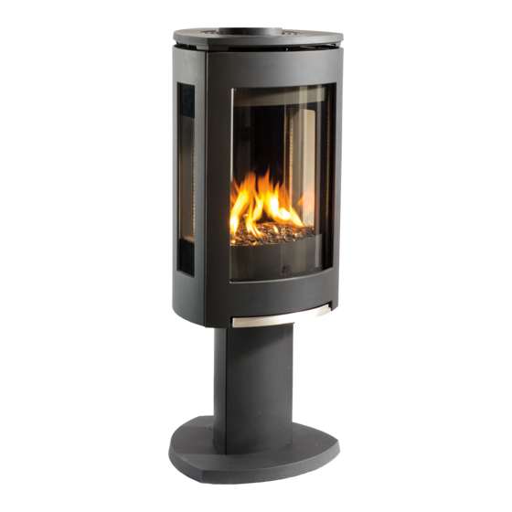
Direct vent gas stove
Hide thumbs
Also See for GF 370 DV:
- Installation and operation instructions manual (40 pages) ,
- Fuel conversion instructions (4 pages) ,
- Adjustment instructions (2 pages)
Table of Contents
Advertisement
WARNING: If the information in these
instructions is not followed exactly, a fire
or explosion may result causing property
damage, personal injury or loss of life.
– Do not store or use gasoline or other
flammable vapors and liquids in the vicinity
of this or any other appliance.
– WHAT TO DO IF YOU SMELL GAS
• Do not try to light any appliance.
• Do not touch any electrical switch; do not
use any phone in your building.
• Immediately call your gas supplier from a
neighbor's phone. Follow the gas supplier's
instructions.
• If you cannot reach your gas supplier, call
the fire department.
– Installation and service must be performed
by a qualified installer, service agency or the
gas supplier.
– In the Commonwealth of Massachusetts,
a carbon monoxide (CO) detector shall be
installed in the same room as the appliance.
This appliance may be installed in an aftermarket,
permanently located, manufactured home or mobile
home, where not prohibited by local codes.
This appliance is only for use with the types of gas
indicated on the rating plate. A conversion kit is
supplied with the appliance.
INSTALLER: Leave this manual with the appliance.
CONSUMER: Retain this manual for future reference.
Installation and
Operation Instructions
ATTENTION : CES INSTRUCTIONS DOIVENT
DEMUERER AVEC LE PROPRIÉTERE D'UNE
MAISON.
AVERTISSEMENT: Assurez-vous de bien suiv-
reles instructions données dans cette notice
pour réduire auninimum le risque d'incendie
ou d'explosion ou pour éviter tout dommage
matériel, toute blessure ou la mort.
– Ne pas entreposer ni utiliser d'essence ni
d'autres vapeurs ou liquides inflammables
dans le voisinage de cet appareil ou de tout
autre appareil.
– QUE FAIRE SI VOUS SENTEZ UNE ODEUR DE
GAZ:
• Ne pas tenter d'allumer l'appareil.
• Ne touchez à aucum interrupteur. Ne
pas vous servir des téléphones se trou-
vant dans le bâtiment où vous trouvez.
• Appelez immédiatement votre fournis-
seur de gaz depuis un voisin. Suivez les
instructions du fournisseur.
• Si vou ne pouvez rejoindre le fournis-
seur de gaz, appelez le service des incend-
ies.
– L'installatione l'entretien doivent être
assurés par un installateur ou un service
d'entretien qualifié ou par le fournisseur
de gaz.
Advertisement
Table of Contents

Related Manuals for Jøtul GF 370 DV


Summary of Contents for Jøtul GF 370 DV
-
Page 1: Operation Instructions
Installation and Operation Instructions WARNING: If the information in these ATTENTION : CES INSTRUCTIONS DOIVENT instructions is not followed exactly, a fire DEMUERER AVEC LE PROPRIÉTERE D’UNE or explosion may result causing property MAISON. damage, personal injury or loss of life. AVERTISSEMENT: Assurez-vous de bien suiv- reles instructions données dans cette notice –... -
Page 2: Installation & Service Tools
DATE OF PURCHASE:____________________________ professionals who are certified in the U.S. by AUTHORIZED DEALER:__________________________ the National Fireplace Institute® (NFI) as NFI Gas ADDRESS ___________________________________ Specialists. PHONE: ____________________________________ INSTALLER:__________________________________ FUEL TYPE:____________________________________ FUEL CONVERSION: NO _______ YES_____ NOTES:________________________________________ 66.07% ______________________________________________ ______________________________________________ Jøtul GF 370 DV... -
Page 3: Table Of Contents
Safety Information ........6 2. Confirm stove contents. Installation Hearth Requirements ......7 The Jøtul GF 370 DV includes the following loose Clearances ..........7 items shipped in the Miscellaneous Hardware bag; Vent Requirements • 4 mm hex key - used to remove the Approved Vent Manufacturers .. -
Page 4: Specifications
138914 Rev. K / 7.27.10 Jøtul GF 370 DV Direct Vent Gas Stove Accessories Manufactured and Distributed by: Jøtul North America Traditional Log Set ..........#156789 Gorham, Maine USA Wishing Rocks Set ..........#156814 Jøtul AS Starfire Glass Kit ............ #156815 Fredrikstad, Norway Reflective Glass Firebox Liner ...... -
Page 5: General Information
138914 Rev. K / 7.27.10 General Information and legal installation. Some areas require a permit THIS HEATER MUST BE INSTALLED AND MAIN- to install a gas burning appliance. Always consult TAINED BY A QUALIFIED SERVICE AGENCY. your local building inspector or authority having DO NOT ATTEMPT TO ALTER OR MODIFY THE jurisdiction to determine what regulations apply in CONSTRUCTION OF THIS APPLIANCE OR ITS COM-... -
Page 6: Safety Information
138914 Rev. K / 7.27.10 Safety Information WARNING! Shock Hazard. Can cause severe injury or death. Due to the high operating temperatures this This appliance is powered by line voltage. appliance should be located out of traffic and Do not try to repair the components in this away from furniture, draperies, etc. -
Page 7: Installation
7” Hearth Requirements Figure 4. Alcove and Wall Clearances. ALCOVE SPECIFICATIONS: The Jøtul GF 370 DV has been approved for installa- tion directly on combustible floor materials, including Maximum Alcove Depth: 21 3/4” (55.2 cm) carpeting. No additional floor protection is required, Minimum Alcove Width: 31 1/4”... -
Page 8: Approved Vent Manufacturers
Vertical Venting and Termination Approved Vent Manufacturers The Jøtul GF 370 DV can be vertically vented through a roof or ceiling. Follow these guidelines The Jøtul GF 370 DV stove is approved for installation with direct vent chimney components supplied by Steep roofs, nearby trees, or predominantly windy ... -
Page 9: Masonry Chimney Conversion
Figure 8. Vent System through a masonry chimney using the Simpson Dura-Vent Chimney Conversion Kit The GF 370 DV is approved for use with direct vent chimney conversion kits in a masonry chimney or #934. Other manufacturers use similar designs. May a prefabricated solid fuel listed chimney. -
Page 10: Horizontal Termination
138914 Rev. K / 7.27.10 Horizontal Termination Figure 9. Minimum vent pipe sections required for Minimum vertical rise from the vent collar is a 24” horizontal termination: section vent pipe. See fig. 9. Minimum horizontal A = 12” with NG run is 12”... -
Page 11: Vent Termination Clearances
138914 Rev. K / 7.27.10 Figure 12. Horizontal termination clearances 24” 74 1/2” A = Clearance above grade, veranda, porch , deck, or balcony G = Clearance to inside corner: ** Min. 6 inches, U.S. / *12 : 12 inches (30 cm) minimum. inches (30 cm) CAN. -
Page 12: Vent Restriction Adjustments
138914 Rev. K / 7.27.10 Vent Restriction Adjustments The Jøtul GF 370 DV features adjustment controls for Exhaust Restrictor Adjustment both intake air and exhaust to accommodate a variety 1. Remove the Trim Rings from the Top Plate. of conditions that result from variables inherent in the 2. -
Page 13: Vent Termination Diagram
138914 Rev. K / 7.27.10 A maximum of two 35 Ft. 90° or four 45° elbows (10.67 m) may be used. When- ZONE ever possible, use 45° elbows instead of 90° elbows as they of- fer less restriction to 30 Ft. -
Page 14: Stove Assembly
138914 Rev. K / 7.27.10 Stove Assembly 1. Glass Frame Removal To access the firebox, use the 4 mm hex key to remove the four socket head screws that attach the glass frame to the firebox. See fig. 18. 2. Routing the Power Supply The power cord located in the valve compartment is connected to the Fan Control Module which is the main power supply for all stove operating functions. -
Page 15: Gas Pressure
138914 Rev. K / 7.27.10 3/8” NPT x 3/8” Flare Fitting Inlet Pressure 1/2” x 3/8” Flare Shut-off Valve Natural Gas: 5.0 WC (1.24 kPa) 7.0 WC (1.74 kPa) Propane: 12.0 WC (2.99 kPa) 14.0 WC (3.48 kPa) 3/8” Flex Tubing Manifold Pressure 3/8”Nipple Natural Gas: 1.6 WC (0.398 kPa) -
Page 16: Fuel Conversion
• Label B - apply to the rating plate in the space indi- cated on the plate. • Small valve label - apply to valve body The GF 370 DV gas stove is shipped from the factory • Conversion instructions equipped to burn Natural gas. Propane fuel conver-... - Page 17 138914 Rev. K / 7.27.10 Pilot Head Ignitor Pilot Orifice Flame Sensor Primary Air Shutter Retainer Clip Injector Regulator Diaphragm Tab & Receptacle Terminals Regulator Tower Use new Torx screws supplied Figure 23. Fuel conversion components and assemblies Using a 4 mm allen wrench, unscrew the pilot 11.
-
Page 18: High Altitude Adjustment
138914 Rev. K / 7.27.10 7. Firebox Panel Installation 6. High Altitude Adjustment for Skamol Panels The decreased atmospheric pressure of higher alti- and optional tudes affects heat value of gaseous fuels. Most gas Reflective Glass Kit 156817 suppliers derate the gas intended for use at eleva- tions above 2000 feet. -
Page 19: Skamol Panel Installation
138914 Rev. K / 7.27.10 Retainer Brackets Figure 25a. Install Rear Skamol Panel. Figure 26a. Bend center tab to Rear Skamol Panel retain glass panels. Figure 26b. Install Rear Glass Panel. Figure 25b. Install Rear Skamol Rear Glass Panel Panels. Figure 26c. -
Page 20: Log Set Installation
138914 Rev. K / 7.27.10 Install the Log Set The three-piece log set includes a bag of ember stones that simulate glowing coals when the burner is operating. Use workgloves and handle the individual logs carefully, supporting each with both hands. Install the Logset and Ember Stones as shown in figures 28-31. -
Page 21: Outer Decorative Glass Panels
138914 Rev. K / 7.27.10 9. Exterior Decorative IMPORTANT! Clean the inside surface of the glass before installation. Glass Panel Kit Assembly Before mounting the support brackets to the stove set each on the end of the glass panel and bend the bracket tabs to hold the panel securely. -
Page 22: System Check
138914 Rev. K / 7.27.10 10. Initial System Check Open outlet The burner and fan control system consists of the fol- Accent Lamp - not used lowing built-in or supplied components: 1) Remote Transmitter - 3, AAA batteries preinstalled 2) Remote Receiver - 4, AA backup batteries preinstalled POWER 3) Fan Control Module - switched 4) Pilot Mode Switch - with 1, 9V backup battery... -
Page 23: Flame Picture Adjustment
138914 Rev. K / 7.27.10 Flame Appearance / Air Shutter Adjustment WARNING: AIR SHUTTER ADJUSTMENTS SHOULD ONLY BE PERFORMED BY A QUALIFIED, PROFESSIONAL SERVICE TECHNICIAN. Locate the Primary Air Shutter control under the fire- box floor above the gas valve. See fig. 37. The shutter is set at the midpoint of its adjustment range at the factory. -
Page 24: Operation
138914 Rev. K / 7.27.10 Jøtul GF 370 DV Ignition Module This is the brain of the system. It allows the pilot to Operation be set up as an IPI or CPI unit. It tells the burner to light or turn off, and provides the ignitor with the electricity needed for sparking. -
Page 25: Control Functions
138914 Rev. K / 7.27.10 Control Functions CPI (Continuous Pilot Ignition) Pilot Mode IPI (Intermittent Pilot Ignition) In most cases you will want to operate the stove in IPI mode. This allows the most efficient use of gas, burn- ing the pilot light only when the thermostat calls for Accent Lamp the burner to ignite. - Page 26 138914 Rev. K / 7.27.10 Remote Transmitter Controls, cont’d. Temperature Indication Display W ith the transmitter in the OFF position, press the Thermostat Key and the Mode Key at the same time. The display screen will show the current room temperature cycling between Farenheit and Celsius Figure 42.
- Page 27 138914 Rev. K / 7.27.10 SMART Thermostat Function This function adjusts the flame intensity according to the difference in the Set Point temperature and the actual room temperature. As the room temperature gets closer to the Set Point, the Smart Function will modulate flame intensity down.
-
Page 28: Wiring Diagrams
Output voltage/frequency/current: 120V / 60 Hz / 5 A Auxiliary switched output: 120V / 60 Hz / 2 A Figure 59. Wiring Diagram - GF 370 DV Fan Fan speed output: 120V / 60 Hz / 1 A Remote Control Transmitter Supply voltage: 4.5 V (three 1.5V AAA batteries) - Page 29 138914 Rev. K / 7.27.10 This page is intentionally blank.
-
Page 30: Maintenance
138914 Rev. K / 7.27.10 Maintenance FOR REPLACEMENT, USE ONLY JØTUL CERAMIC GLASS PANEL KIT 156817. DO NOT USE ANY OTHER TYPE OF GLASS WITH THIS This appliance and its venting system should be APPLIANCE. inspected before use and at least annually by a quali- fied service technician. -
Page 31: Battery Replacement
138914 Rev. K / 7.27.10 Initializing the Remote Control Figure 61. Each time you replace the batteries, you will need to 156817 Glass initialize communication between the Receiver and Replacement the Transmitter. Kit includes gasket and spare 1. Place the slider switch in the REMOTE position. retainer clips. -
Page 32: Illustrated Replacement Parts
138914 Rev. K / 7.27.10 Figure 64. Firebox Part Identification. No. Part Number Description No. Part Number Description 9911 Bolt, Hex Cap, M6x45, DIN 933, Class 8.8, Blk 22298392 Simpson DV Starter Collar, GF 370, MB 9962 Bolt, Hex Cap M6x10 DIN 933 8.8 Ser Flange Blk 222988 Light Box, Inner 117917... - Page 33 138914 Rev. K / 7.27.10 Figure 65. External parts identification No. Part Number Description Part Number Description 156843 Lower Door Hinge Asy. GF 370, MB 9962 Bolt, Hex Cap M6x10 DIN 933 8.8 Ser Flange Blk 156835 Replacement Outer Side Glass, GF 370 99115 Bolt, Hex Head M8 x 12 Blk 10447092...
- Page 34 138914 Rev. K / 7.27.10 Figure 66. Spud Assembly parts identification...
- Page 35 138914 Rev. K / 7.27.10 Part Number Description 118214 Screw, #8 X 3/8”, Taptite, SLHWH, SZPL Use only genuine Jøtul Replacement Parts 117917 Screw, HWH SMA 8 x 1/2 SL Blk Oxide available from your local Authorized Jøtul 117967 Screw, Pan Head #7 x 3/8 PH SMA Zinc Dealer or by contacting: 117968 Nut, M6 Serrated Flange plain...
-
Page 36: Mobile Home Installation
Appendix A Mobile Home Installation Correct Flame Pictures The Jøtul GF 370 DV can be installed for use in a mobile home in the U.S. and Canada provided: 1. The stove must be secured to the floor of the mobile home. There is a hole for this purpose,... - Page 37 138914 Rev. K / 7.27.10...
-
Page 38: Limited Warranty
138914 Rev. K / 7.27.10 Jøtul Gas Product installation instructions contained in this owner’s manual or local and/or national fire and building regulations. Limited Warranty 3) Damage due to service performed by an installer, service agency or gas supplier, unless otherwise agreed to in writing by JØTUL. 4) Labor or other costs associated with the repair of gas controls, This warranty policy applies to gas products identified by plumbing, burners, log set, or sheet metal firebox beyond the warranty... -
Page 39: Waranty Statement
138914 Rev. K / 7.27.10 LIGHTING INSTRUCTIONS FOR YOUR SAFETY, READ BEFORE LIGHTING. WARNING: IF YOU DO NOT FOLLOW THESE INSTRUCTIONS EXACTLY, A FIRE OR EXPLOSION MAY RESULT CAUSING PROPERTY DAMAGE, PERSONAL INJURY, OR LOSS OF LIFE. A. This appliance is equipped with an ignition device which automatically lights the pilot. - Page 40 138914 Rev. K / 7.27.10 This appliance must be installed in conformance with local and national building regulations. Before beginning the installation, it is important that the these instructions be carefully read and understood. Jøtul maintains a policy of continual product development. Consequently, products may differ in specifi- cation, color or type of accessories from those illustrated or described in various publications.