Table of Contents
Advertisement
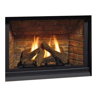
Regency P33CE
WARNING:
If the information in these instructions are not followed exactly,
a fi re or explosion may result causing property damage,
personal injury or loss of life.
FOR YOUR SAFETY
Do not store or use gasoline or other fl ammable vapors and
liquids in the vicinity of this or any other appliance.
Installation and service must be performed by a qualifi ed
installer, service agency or the gas supplier.
Tested by:
919-125
FPI FIREPLACE PRODUCTS INTERNATIONAL LTD. 6988 Venture St., Delta, BC Canada, V4G 1H4
Gas Fireplace
Installer: Please complete the details on the back cover
and leave this manual with the homeowner.
Homeowner: Please keep these instructions for future reference.
Owners &
Installation Manual
MODEL: P
P
www.regency-fi re.com
FOR YOUR SAFETY
What to do if you smell gas:
Do not try to light any appliance
Do not touch any electrical switch:
do not use any phone in your
building.
Immediately call your gas supplier
from a neighbour's phone. Follow
the gas supplier's instructions.
If you cannot reach your gas
supplier, call the fi re department.
3
3CE-NG Natural Gas
3
3CE-LP Propane
06/12/12
Advertisement
Table of Contents

Related Manuals for Regency P33CE-NG


Summary of Contents for Regency P33CE-NG
- Page 1 Owners & Regency P33CE Installation Manual Gas Fireplace MODEL: P 3CE-NG Natural Gas 3CE-LP Propane www.regency-fi re.com WARNING: FOR YOUR SAFETY If the information in these instructions are not followed exactly, What to do if you smell gas: a fi re or explosion may result causing property damage, Do not try to light any appliance personal injury or loss of life.
- Page 2 Please ® take a moment now to acquaint yourself with these instructions and the many features of your Regency Fireplace. P33CE Direct Vent Gas Fireplace...
- Page 3 INFORMATION FOR MOBILE/MANUFACTURED HOMES AFTER FIRST SALE ® This Regency product has been tested and listed by Warnock Hersey/Intertek as a Direct Vent Wall Furnace to the following standards: VENTED GAS FIREPLACE HEATERS ANSI Z21.88-2009/CSA 2.33-2009 and GAS-FIRED APPLIANCES FOR USE AT HIGH ALTITUDES CAN/CGA-2.17-M91.
-
Page 4: Table Of Contents
Framing Dimensions............13 Burner & Log Assembly ..........54 Framing & Finishing.............14 Venting Introduction .............16 WARRANTY Exterior Vent Termination Locations ......17 Regency ® Direct Vent fl ex System ......18 Warranty..............55 Installation Procedures ..........19 Rigid Pipe Venting Systems ........20 4” x 6-5/8” Rigid Pipe Cross Reference Chart .....21 Rigid Pipe Venting Arrangements .......23... -
Page 5: Safety Label
4001172 MAY BE INSTALLED IN MANUFACTURED (MOBILE) HOMES AFTER FIRST SALE. Minimum Clearances to Combustibles Minimum Clearances to Combustibles NATURAL GAS: Model P33CE-NG APPAREIL FONCTIONNANT AU NATURAL GAS Degagement Minimum De Materiaux Combustibles Degagement Minimum De Materiaux Combustibles 33CE CONCU POUR ETRE POELE: Modéle... -
Page 6: Requirements
REQUIREMENTS MA Code - CO Detector (for the State of Massachusetts only) 5.08: Modifications to NFPA-54, Chapter 10 (2) Revise 10.8.3 by adding the following additional requirements: (a) For all side wall horizontally vented gas fueled equipment installed in every dwelling, building or structure used in whole or in part for residential purposes, including those owned or operated by the Commonwealth and where the side wall exhaust vent termination is less than seven (7) feet above finished grade in the area of the venting, including but not limited to decks and porches, the following requirements shall be satisfied:... -
Page 7: Installation
6) Venting terminals shall not be recessed into a wall ANCE. TODDLERS, YOUNG CHILDREN or siding. The P33CE-NG or P33CE-LP Direct Vent Fireplace AND OTHERS MAY BE SUSCEPTIBLE 7) Any safety glass removed for servicing must must be installed in accordance with these TO ACCIDENTAL CONTACT BURNS. -
Page 8: Installation Checklist
INSTALLATION 2) If required, adjusting the primary air to ensure inspector, dealer, or installer review your plans INSTALLATION that the fl ame does not carbon. First allow the before installation. unit to burn for 15-20 min. to stabilize. CHECKLIST Note: For vent terminations see "Exterior Vent Termination Locations"... -
Page 9: Unit Dimensions
INSTALLATION UNIT DIMENSIONS 23" 584mm 2-1/2" 34-9/16" [64mm] [878mm] NAILING STRIP 3" (76mm) 26" 660mm 29-7/16" 747mm 4 SIDED FACEPLATE DIMENSIONS MANTEL DIMENSIONS 42-5/16" (1074mm) 47-9/16" 5-1/8" 3" (1207mm) 9" (76mm (130mm) (229mm) 29-9/16" 8-1/8" (750mm) (206mm) 2" 52-1/8" (51mm) (1324mm) P33CE Direct Vent Gas Fireplace... -
Page 10: Clearances
INSTALLATION CLEARANCES The clearances listed below are Minimum distances unless otherwise stated: A major cause of chimney related fi res is failure to maintain required clearances (air space) to combustible materials. It is of the greatest importance that this fi replace and vent system be installed only in accordance with these instructions. WARNING Caution Requirements Fire hazard is an extreme risk... -
Page 11: Combustible Mantels
INSTALLATION COMBUSTIBLE MANTELS Because of the extreme heat this fi replace emits, the mantel clearances are critical. Combustible mantel clearances from top of unit are shown in the diagram below. Note: A non-combustible mantel may be installed at a lower height if the framing is made of metal studs covered with a non-combustible board. This drawing is to scale at 1:6 (one inch = 6 inches). -
Page 12: Mantel Leg Clearances
INSTALLATION MANTEL LEG CLEARANCES Combustible mantel leg clearances from side of unit as per diagram: Top View Side opening of Unit Maximum 1-1/2" projection at 2" minimum 6-3/4" clearance. Allowable mantel leg projection 9" P33CE Direct Vent Gas Fireplace... -
Page 13: Framing Dimensions
INSTALLATION FRAMING DIMENSIONS Non-combustible Header 2X4 HEADER (steel stud on edge) DETAIL N SCALE 1 : 6 NOTE: If this is an outside corner, the Floor minimum distance between the vent and the outside corner is 6" (15cm) with AstroCap termination cap or 12" (30cm) with Rigid Vent termination cap. -
Page 14: Framing & Finishing
INSTALLATION FRAMING & FINISHING 1. There are 8 (eight) side nailing strips and one top nailing strip available on the unit. One set of four (4) are for a clean fi nish (board only, painted) installation, the other set are for a non-combustible fi nish (ex. tile, concrete, mantel, surround) as they are set back 1/2" (13mm). The top nailing strip is adjustable to 1/2"... - Page 15 INSTALLATION 6) If applying a non-combustible facing it may be installed over the metal surface of the fi rebox of the unit in the area shown below. NON-COMBUSTIBLE BOARD ONLY (PAINTED FINISH) WOOD STUD Combustible Material 1/2" DRYWALL DO NOT EXTEND Non-combustible Material (3-1/2"...
-
Page 16: Venting Introduction
There are 5 vent systems approved for use with the P33CE: the Regency ®... -
Page 17: Exterior Vent Termination Locations
INSTALLATION EXTERIOR VENT TERMINATION LOCATIONS Minimum Clearance Requirements Canada Clearance above grade, veranda, porch, deck, or balcony 12"(30cm) 12"(30cm) Clearance to window or door that may be opened 12"(30cm) 9" (23cm) Clearance to permanently closed window Vertical clearance to ventilated soffi t located above the terminal within a horizontal distance of 2 feet (61cm) 18"(46cm) 18"(46cm) from the center line of the terminal (check with the local code) -
Page 18: Regency ® Direct Vent Fl Ex System
Notes: 1) Liner sections should be continuous 6-7/8" without any joints or seams. (173mm) ® 2) Only Flex pipe purchased from Regency dia. Flue pipe may be used for Flex installations. See Figure 1 below for Alternate Caps. MINIMUM MINIMUM... -
Page 19: Installation Procedures
INSTALLATION INSTALLATION PROCEDURES ® for Regency Direct Vent System (Flex) 1) Locate the unit in the framing, rough in the gas *If this is an outside corner, the minimum distance between the vent and the outside (preferably on the right side of the unit) and the corner is 6"... -
Page 20: Rigid Pipe Venting Systems
INSTALLATION RIGID PIPE VENTING SYSTEMS Horizontal or Vertical Terminations The minimum components required for a basic horizontal termination are: Vertical Terminal AstroCap Horizontal Termination Cap Elbow Storm Collar Rigid Pipe Adaptor Vinyl Siding Wall Thimble Standoff (Optional) Length of pipe to suit wall thickness Flashing (see chart) For siding other than vinyl furring strips may be used,... -
Page 21: 4" X 6-5/8" Rigid Pipe Cross Reference Chart
Components from different Manufacturers may not be mixed. Not All Rigid Pipe components are available directly from FPI. 4” X 6- 5/8” RIGID PIPE CROSS REFERENCE CHART Components from different Manufacturers may not be mixed. Not all rigid pipe components are available directly from Regency. Description... - Page 22 INSTALLATION Description Selkirk American Metal Security ICC Excel Simpson Metal-Fab™ Direct Temp™ Secure- Vent® Direct ® Products® Direct Vent Pro Sure Seal Amerivent Direct Attic Insulation Shield 12” 46DVA-IS 4DAIS12 SV4RSA N/A@ FPI Attic Insulation Shield - 36” 4DAIS12 TM-4AS Cold Climates Basic Horizontal Termination Kit (A) Disc.
-
Page 23: Rigid Pipe Venting Arrangements
INSTALLATION RIGID PIPE VENTING ARRANGEMENTS Vertical Terminations (Propane & Natural Gas) The shaded area in the diagram shows all allowable combinations of straight vertical and offset to vertical terminations, using one 90 elbow, with rigid pipe vent systems for Propane and Natural Gas. •... - Page 24 INSTALLATION The P33CE is approved for a maximum 40 ft. straight vertical, with rigid pipe vent systems for Propane and Natural Gas. The shaded area in the diagram shows all allowable combinations of straight vertical and offset to vertical terminations with rigid pipe vent systems for Propane and Natural Gas.
-
Page 25: Horizontal Terminations
Note: Must use optional rigid pipe adaptor (Part # 510-994) when using rigid pipe vent systems. (Refer "Rigid Pipe Venting Systems" Section) A vent guard should be used whenever the termination is lower than the specifi ed minimum or as per local codes. Note: Regency ® Direct Vent System (Flex) is only approved for horizontal terminations. - Page 26 INSTALLATION Horizontal Venting with Two (2) 90 Elbows Horizontal Venting with Three (3) 90 Elbows One 90 elbow = Two 45 elbows. One 90 elbow = Two 45 elbows. Option H + H1 With these options, maximum Option H + H1 + H2 With these options, maximum total pipe total pipe length is 30 feet...
- Page 27 INSTALLATION Horizontal Venting with Three (3) 90 Elbows One 90 elbow = Two 45 elbows. Option V + V1 H + H1 With these options, maximum total pipe 2' Min. 1' Max. 3' Min. 4' Max. length is 30 feet with minimum of 12 feet 3' Min.
- Page 28 INSTALLATION Vertical Venting with Three (3) 90 Elbows One 90 elbow = Two 45 elbows. Option H + H1 V + V1 With these options, max. total 1' Max. 1' Min. 3' Max. 3' Min. pipe length is 30 feet with min. 2' Max.
-
Page 29: Vertical Termination With Co-Linear Flex System
INSTALLATION VERTICAL TERMINATION WITH CO-LINEAR FLEX SYSTEM THE APPLIANCE MUST NOT BE Masonry chimneys may take various contours which the fl exible liner will accommodate. However, CONNECTED TO A CHIMNEY FLUE SERVING keep the fl exible liner as straight as possible, avoid unnecessary bending. A SEPARATE SOLID FUEL BURNING APPLIANCE. -
Page 30: Venting Arrangements - Vertical Terminations
INSTALLATION VENTING ARRANGEMENTS - VERTICAL TERMINATIONS with Co-linear Flex System for both Residential & Manufactured Homes into Masonry Fireplaces Horizontal Distance (Feet) When using Contemporary Faceplate, unit must be raised 1". The shaded area in the diagrams show the allowable vertical terminations. P33CE Direct Vent Gas Fireplace... -
Page 31: Unit Installation With Horizontal Termination
INSTALLATION UNIT INSTALLATION WITH HORIZONTAL TERMINATION b) Horizontal runs of vent must be supported Install the vent system according to the Riser Vent every three feet. Wall straps are available Diagram 2a manufacturer's instructions included with the Termination for this purpose. components. -
Page 32: Unit Installation With Vertical Termination
INSTALLATION 8) Slide the appliance and vent assembly towards 4) Assemble the desired lengths of pipe and the wall carefully inserting the vent pipe into the elbows. Ensure that all pipes and elbow con- vent cap assembly. It is important that the vent nections are in the fully twist-locked position pipe extends into the vent cap suffi... -
Page 33: Pilot Adjustment
INSTALLATION PILOT ADJUSTMENT GAS PIPE PRESSURE P33CE-NG System Data TESTING Burner Inlet Orifi ce Sizes: Periodically check the pilot fl ames. Correct fl ame pattern has two strong blue fl ames: Max. Input Rating 20,000 Btu/h 1 fl owing around the fl ame sensor and 1 The appliance must be isolated from the gas supply Min. -
Page 34: Conversion From Ng To Lp
INSTALLATION CONVERSION FROM NG TO LP For P33CE Using SIT 886 NOVA Gas Valve THIS CONVERSION MUST BE DONE BY A QUALIFIED GAS FITTER IF IN DOUBT DO NOT DO THIS CONVERSION!! Reinstall new burner orifice LPG Each Kit contains one LPG stamped #54 and tighten. -
Page 35: Optional Brick Panels
INSTALLATION LOG SET INSTALLATION OPTIONAL BRICK D) 251 A) 250 PANELS Read the instructions below carefully 1) Undo the bottom 2 door latches and open and and refer to the diagrams. If logs remove glass door. Remove logs. are broken do not use the unit until they are replaced. -
Page 36: Standard Flush Door And Screen
INSTALLATION 8) Pull off ember size pieces of rock wool and gently place them on the front of the burner tray in the places shown in the photo below. Do not compress the rock wool, leave it loose. Separate platinum embers and place them on the front of the burner on and around the rock wool. -
Page 37: Gt Remote Installation
INSTALLATION GT REMOTE INSTALLATION 1) Shut off the gas supply and disconnect all power to the unit. 8) Plug in receiver DC supply wire - as shown below. 2) Remove the louvers, bay door or faceplate if installed. 3) Disconnect battery pack - located on the fl oor of the unit, as shown below and discard. -
Page 38: Gtm Remote Installation
INSTALLATION GTM REMOTE INSTALLATION 6) Identify wires in the GTM/GTMF remote wiring harness. 1) Shut off the gas supply and disconnect all power to the unit. (see wiring diagram.) 2) Remove the louvers, bay door or faceplate if installed. 7) Connect the TPTH and TH wires - green to green and white to white as shown below. - Page 39 INSTALLATION 10) Install the stepper motor in the same location the hi/lo knob was 15) Install 4-AA batteries into the receiver. removed from - with 2 screws as shown below. 16) Bundle all wires together and clip with supplied wire clip - as shown below.
-
Page 40: Optional 4-Sided Faceplate Installation
INSTALLATION OPTIONAL 4-SIDED FACEPLATE INSTALLATION If installing the optional faceplate ensure the combustible and non combustible material around the unit are installed 3. Line up the middle rib on backside of faceplate with middle indent on bracket. This will centre the faceplate and allow 1/16" adjustment from side to side. fl... -
Page 41: Optional Mantel Installation
INSTALLATION OPTIONAL MANTEL INSTALLATION 3. Repeat steps 1 and 2 to install lower bracket - screw locations are shown If installing the optional mantel ensure the combustible and below. non combustible material around the unit are installed fl ush with the unit. (See Diagram 1 below). The mantel cannot be installed if materials are not fl... -
Page 42: Wall Thermostat
WALL THERMOSTAT REMOTE CONTROL WALL SWITCH ® Use the Regency Remote Control Kit approved 1) Run the supplied 10' of wire through the right A wall thermostat may be installed if desired, for this unit. Use of other systems may void your or left side gas inlet opening. -
Page 43: Wiring Diagrams
INSTALLATION WIRING DIAGRAMS This heater does not require a 120V A.C. supply for operation. In case of a power failure, the burner switch and the optional remote control/thermostat will continue to operate. However, a 120V A.C. power supply is needed for the fan/blower operation. (Do not cut the ground terminal off under any circumstances.) NOTE: Even if the fan is not purchased with the unit, it is still a good idea to bring power to the receptacle box (provided with the unit) in case the fan is installed at a later date. -
Page 44: Ac Power Adaptor Installation (For Surefi Re Systems)
INSTALLATION AC POWER ADAPTOR INSTALLATION (FOR SUREFIRE SYSTEMS) An optional AC power adaptor may be installed as a constant power source for the SureFire system. IMPORTANT: Recommend removing the 4-AA batteries in the SureFire receiver. This will avoid battery leakage and power drainage. 4-AA Battery pack may be re-installed into receiver during power outages. NOTE: For all Gas Fireplaces 120 volt power must be brought to the receptacle box inside the (provided with the unit). -
Page 45: Installing The Optional Fan (Prior To Unit Installation)
INSTALLATION INSTALLING THE OPTIONAL FAN (PRIOR TO UNIT INSTALLATION) 6. Attach the fan control box to the Control Plate. (Diagrams 5 & 6. An optional fan can been installed prior to unit installation by following these steps. 1. Remove lower base cover by tilting forward and removing one screw on each Fan Control Box side to release. -
Page 46: Optional Fan Wiring Diagram
INSTALLATION OPTIONAL FAN WIRING DIAGRAM Lockwasher Ground Star washer #8 Ground Lug (for mobile home) Neutral Green Live Ground 120V AC 60 Hz Black Fan Thermodisc Rotary Speed (normally open) Control ground wire NOTE: Wiring schematics for P36E-4 (120 Volts), plug-in fan circuit with speed control switch on wall. -
Page 47: To Remove The Fan
INSTALLATION 8. Remove the 12 screws securing the valve tray assembly in place 13. Remove lower base cover by removing 2 screws and lifting out (Diagram 8). (Diagram 4) and then lift the entire assembly out. Diagram 8 14. Attach the fan control box to the Control Plate. (Diagrams 9 & 10. Fan Control Box Diagram 4 Valve Tray Assembly 9. -
Page 48: Operating Instructions
OPERATING INSTRUCTIONS COPY OF THE LIGHTING PLATE INSTRUCTIONS FOR YOUR SAFETY READ BEFORE LIGHTING This appliance must be installed in accordance with local codes, if any; if none, follow the National Fuel Gas Code, ANSI Z223.1/NFPA 54, or Natural Gas and Propane Installation Codes, CSA B149.1. WARNING: If you do not follow these instructions exactly, a fire or explosion may result causing property damage, personal injury or loss of life. -
Page 49: Operating Instructions
Note: Aeration Adjustment should only the "OFF" position. be performed by an authorized Note: When the glass is cold and the ® Regency Installer at the time of appliance is lit, it may cause 2) Press "OFF" on the remote control. installation or service. -
Page 50: Maintenance Instructions
3) The heater is fi nished in a heat resistant forming in the inner liner, and subsequently your fan speed control. paint and should only be refi nished with heat dripping out the joints, Continuous resistant paint. Regency ® uses StoveBright condensation can cause corrosion of Burner Tray: Paint - Metallic Black #6309. -
Page 51: Glass Gasket
The glass must have Flush Front (Part # 936-155). gasketing around it. DOOR GLASS Your Regency ® fi replace is supplied with high temperature, 5 mm Neoceram ceramic glass that will withstand the highest heat that your unit will produce. -
Page 52: Removing Valve
1. Install new valve assembly. Ground 2. Reverse steps 7-1. Diagram 2 5. Disconnect the inlet gas line. 6. Disconnect the EV1, EV2, and ground wires from the valve - as shown below. Diagram 3 Regency® P33CE Zero Clearance Direct Vent Gas Fireplace... -
Page 53: Main Assembly
MAIN ASSEMBLY Part # Description Part # Description Burner Assembly Orifi ce # 44 NG 770-523 Thermodisc cage 904-163 Orifi ce # 54 LP 437-515 Valve Assembly 911-004 886 Profl ame Valve 432-917 Fan Assembly 437-024 Screen glass guard 919-125 Manual 433-538 Glass Door Assembly... -
Page 54: Parts List
PARTS LIST BURNER & LOG ASSEMBLY Part Description 53) 430-055 Gasket - Valve Access Plate - NG/LP 54) 910-421 Pilot ON/OFF Extension Knob 55) 910-422 Flame HI/LOW Extension Knob 433-574E/P Valve Assy - Natural Gas 433-576E/P Valve Assy - Propane 57) 911-004 Valve SIT - NG 911-005... -
Page 55: Warranty
It is the general practice of FPI to charge for larger, higher priced replacement parts and issue credit once the replaced component has been returned to FPI and e for manufacturer defect. The authorized selling dealer is responsible for all in-fi eld service work carried out on your Regency product. FPI will not be liable for results or costs of workman unauthorized service persons or dealers. - Page 56 Dealer Name & Address: ______________________________________________ ___________________________________________________________________ Installer: ___________________________________________________________ Phone #: ___________________________________________________________ Date Installed: ______________________________________________________ Serial No.: __________________________________________________________ Regency and SureFire are trademarks of FPI Fireplace Products International Ltd. Printed in Canada © Copyright 2012, FPI Fireplace Products International Ltd. All rights reserved.