Table of Contents
Advertisement
Quick Links
MULTI-FORMAT MONITOR
BEDIENUNGSANLEITUNG :MULTI-SYSTEM-MONITOR
MANUEL D'INSTRUCTIONS :MONITEUR MULTI-FORMAT
MANUALE DI ISTRUZIONI :MONITOR MULTI-FORMATI
INSTRUCCIONES
!"
DT-V1900CG
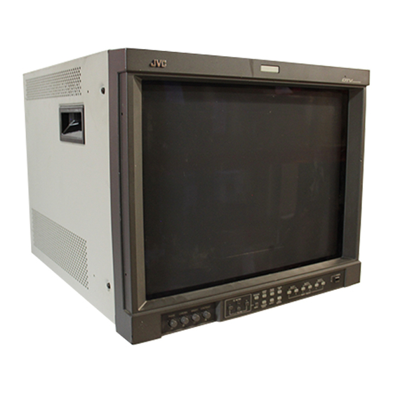
The illustration shows the DT-V1900CG with provided wide
mask attached.
Die Abbildung zeigt Modell DT-V1900CG mit angebrachtem
mitgelieferten Breitformat-Vorsatzrahmen.
L'illustration montre le DT-V1900CG avec le masque large fourni
monté.
L'illustrazione raffigura il DT-V1900CG con montata la maschera
per visione panoramica, fornita in dotazione.
La ilustración muestra el DT-V1900CG con el protector
panorámico suministrado colocado.
!"#$%&'()
:MONITOR MULTIFORMATO
:
!"#°C
-
!"#$
INSTRUCTIONS
UNDER
PULSE
COLOR
DEGAUSS
SCAN
CROSS
OFF
MUTING
SLOT 1
SLOT 2
SLOT 3
A
B
C
D
E
F
MENU
SCREENS
ASPECT
AREA
INPUT SELECT
VOLUME
CHECK
MARKER
LCT1116-001B
POWER
Advertisement
Table of Contents

Related Manuals for JVC DT-V1900CG


Summary of Contents for JVC DT-V1900CG
- Page 1 The illustration shows the DT-V1900CG with provided wide mask attached. Die Abbildung zeigt Modell DT-V1900CG mit angebrachtem mitgelieferten Breitformat-Vorsatzrahmen. L’illustration montre le DT-V1900CG avec le masque large fourni monté. L’illustrazione raffigura il DT-V1900CG con montata la maschera per visione panoramica, fornita in dotazione.
-
Page 2: Table Of Contents
MULTI-FORMAT MONITOR DT-V1900CG Thank you for purchasing this JVC Multi-Format Monitor. Before using it, read and follow all instructions carefully to take full advantage of the monitor’s capabilities. For Customer Use: Enter below the Serial No. which is located on the rear of the cabinet. Retain this information for future reference. -
Page 3: Safety Precautions
● Video or audio signals cannot be input to this monitor without optional input cards. ● In these instructions, all explanations (except where noted) refer to the DT-V1900CG with input cards installed. SCREEN BURN ● It is not recommended to keep a certain still image displayed on screen for a long time as well as displaying extremely bright images on screen. - Page 4 POWER CONNECTION The power supply voltage rating of this product is AC 120 V (For U.S.A. and Canada only) and AC 230 V (For European countries or United Kingdom), the power cord attached conforms to the following power supply voltage and countries. Use only the power cord designated to ensure Safety and EMC regulations of each countries.
-
Page 5: Controls And Features
CONTROLS AND FEATURES FRONT VIEW <Front Panel> DEGAUSS SCAN UNDER CROSS PULSE COLOR MUTING SLOT 1 SLOT 2 SLOT 3 POWER MENU ASPECT INPUT SELECT VOLUME SCREENS CHECK AREA MARKER Tally lamp Lights when the tally control signal is ON. Set the MAKE/ TRIGGER terminal’s tally control in the REMOTE (external control) terminal setup menu. -
Page 6: Rear Panel
REAR/SIDE VIEW <Rear Panel> MAKE RS-232C MAIN POWER COLOR OFF button/lamp Press the COLOR OFF button. The button lights and the screen becomes monochrome. When the COLOR OFF button is pressed while lit, the light goes off and the normal screen is restored. Use this function to confirm the noise in the brightness signal or to confirm the white balance. -
Page 7: Controls And Features (Input Card: Optional)
CONTROLS AND FEATURES (INPUT CARD: OPTIONAL) COMPONENT/RGB INPUT CARD (OPTIONAL: IF-C01COMG) /B-Y /B-Y HD/C AUDIO Compatible signal formats: 480/60i, 576/50i, 576/50p, 480/60p, 720/60p, 1035/60i, 1080/50i, 1080/60i, 1080/24psF VIDEO INPUT CARD (OPTIONAL: IF-C01PNG) VIDEO 1 VIDEO 2 Y/C IN EXT.SYNC AUDIO 1 AUDIO 2 Compatible signal formats: NTSC (3.58 MHz), PAL (4.43 MHz), black-and-white... - Page 8 SDI INPUT CARD (OPTIONAL: IF-C01SDG) SWITCHED SDI 1 SDI 2 AUDIO 1 AUDIO 2 Compatible signal formats: 480/60i, 576/50i, 576/50p HD SDI INPUT CARD (OPTIONAL: IF-C01HSDG) SWITCHED HD SDI 1 HD SDI 2 AUDIO Compatible signal formats: 720/60p, 1035/60i, 1080/50i, 1080/60i, 1080/24psF Output terminal for a selected component serial digital signal...
- Page 9 CONTROLS AND FEATURES (INPUT CARD: OPTIONAL) HD SDI INPUT CARD (OPTIONAL: IF-C12HSDG) E.AUDIO HD SDI 1 E.AUDIO HD SDI 2 Compatible signal formats: 720/60p, 1080/50i, 1080/60i, 1035/60i, 1080/24psF, EMBEDDED AUDIO (cont'd) Input and output terminals for HD SDI 1 component serial digital signals Input (IN) and output (OUT) terminals for HD serial digital signals.
-
Page 10: Preparation
(on the rear side of the monitor) in which you are going to install the card. Slot cover Rear side of the DT-V1900CG Multi-Format Monitor 3. Insert the Input Card’s board (green- coloured) into the slot, fitting the board into the guide rails on the top and bottom of the slot. -
Page 11: Attaching The Power Cord Holder
PREPARATION ATTACHING THE POWER CORD HOLDER The provided Power Cord Holder prevents accidental disconnection of the AC power cord from the AC inlet. The Power Cord Holder consists of two parts; a case and cover. 1. Attach the Power Cord Holder case to the AC inlet on the back of the monitor with 2 screws (provided). -
Page 12: Basic Menu Operations (Main Menu, Setup Menu)
BASIC MENU OPERATIONS (MAIN MENU, SETUP MENU) ABOUT MENU SCREENS This monitor features a MAIN MENU (main menu screen) and a SETUP MENU (setup menu screen). The MAIN MENU contains the functions normally used, and the SETUP MENU contains the settings required for initial setup. -
Page 13: How To Use "Main Menu
HOW TO USE “MAIN MENU” “MAIN MENU” ITEMS The following items appear in MAIN MENU. Items Functions APERTURE CONTROL Compensates the frequency characteristics of the input video signal. SLOT CONDITION Displays the status of the input cards installed in each of the input card slots. sub menu POSITION Selects the display position of the sub menu superimposed on the screen. - Page 14 ITEM CONTENTS AND ADJUSTMENT RANGE/SETTINGS 1. APERTURE CONTROL Compensates the frequency characteristics of the input video signal. Press the button to display the setting menu illustrated on the right. NOTE : APERTURE CONTROL is not displayed when the RGB signal is input. Item : LEVEL Adjustment...
- Page 15 HOW TO USE “MAIN MENU” 5. AREA MARKER-R Items : Selects the size marker for the other screen ratio (aspect) used when the screen ratio is 16:9. (for external control) Settings : OFF/16:9/4:3/13:9/14:9/MODE 1/MODE 2 Functions : OFF: The marker is not displayed. 16:9/4:3/13:9/14:9: Displays the marker (a white quadrangle) showing the screen size of each aspect ratio.
-
Page 16: How To Use "Setup Menu
HOW TO USE “SETUP MENU” “SETUP MENU” ITEMS Items Functions 1 FUNCTION SETTING Displays the monitor’s power-up time or the total usage time. 2 PICTURE SUB ADJ. Performs approximate adjustments using the control knobs on the front panel. 3 COLOR TEMP./BAL. Sets or adjusts the colour temperature or white balance. - Page 17 HOW TO USE “SETUP MENU” ITEM CONTENTS AND ADJUSTMENT RANGE/SETTINGS 1. FUNCTION SETTING Selects the colour system and displays the monitor’s power-up time or the total usage time. Press the button to display the setting menu illustrated on the right. Item : COLOR SYSTEM Settings...
- Page 18 Item : CONTRAST Adjustment range : –20 ~ 00 ~ +20 Function : For approximate adjustment of the picture contrast. Before adjustment, set the CON- TRAST knob on the front panel to 0. Item : BRIGHT Adjustment range : –20 ~ 00 ~ +20 Function : For approximate adjustment of the picture brightness.
- Page 19 HOW TO USE “SETUP MENU” 4. SIZE/POSI. ADJ. Adjusts the size or position of the picture. Press the button to display the setting menu illustrated on the right. Item : H.SIZE Adjustment range : –20 ~ 00 ~ +20 (*) Function : Adjusts the horizontal screen size.
- Page 20 6. STATUS DISPLAY Makes the status of the input signal appear or disappear on the screen. Press the button to display the setting menu illustrated on the right. Item : STATUS DISPLAY Settings : ON/OFF Function : Makes the format name appear or disappear when signals are input and the signal status appear or disappear when the input signal is changed.
-
Page 21: How To Use External Control
HOW TO USE EXTERNAL CONTROL ABOUT EXTERNAL CONTROL The Multi-Format Monitor has two external control terminals. One is the MAKE/TRIGGER terminal, which allows the monitor to be controlled by the MAKE(make contact) or TRG. (trigger contact) method selected in the function setting. MAKE (make contact system): Controls the function by stable disconnection (terminal open) or short-circuiting (short with GND of 15th terminal) of the controlled terminal. - Page 22 HOW TO USE THE RS-232C TERMINAL You can control the monitor from your PC via the RS-232C terminal. For details on operating the monitor from the PC, consult your dealer or service centre for details. 1. Cable Prepare a straight cable with a D-sub connector (9-pin, female) and a D-sub connector (9-pin, male) 2.
-
Page 23: Troubleshooting
TROUBLESHOOTING Solutions to common problems related to your monitor are described here. If none of the solutions presented here solve the problem, unplug the monitor and consult a JVC-authorised dealer or service centre for assistance. Problems Points to be checked... - Page 24 Problems Points to be checked Irregular colour Is the monitor placed or moved close to a speaker or any other device incorporating a magnet? Has the position of the monitor been changed with the power on? Wrong picture Has the picture position, size or position, wrong distortion been changed? picture size...
-
Page 25: Self-Check Indications
TROUBLESHOOTING SELF-CHECK INDICATIONS When the screen goes blank, and one or more of the INPUT SELECT A through F buttons on the front control panel start blinking... This monitor has a self-check function, which allows it to detect malfunctions and alert you. This makes trouble-shooting easier. Whenever a problem occurs, a combination of “self-check indicators”... -
Page 26: Specifications
SPECIFICATIONS Type : Multi-Format Monitor Picture Tube : 19" measured diagonally Effective Screen Size : Width : 370 mm Height : 270 mm Diagonal : 460 mm Scanning Frequency : H : 15 kHz/15 kHz – 45 kHz V : 50 Hz – 100 Hz Video Band : Component : 25 MHz (–3 dB) Video (Y/C) : 8 MHz (–3 dB) - Page 27 SPECIFICATIONS Compliant Signal Formats of Each Input Card Input Signals NTSC (3.58 MHz) PAL (4.43 MHz) Black-and-White (50 Hz/60 Hz) 480/60i (525i) 480/60p (525p) 576/50i 576/50p 720/60p (720p) 1080/50i 1080/60i (1125i) 1035/60i (1125i) (*1) 1080/24psF EMBEDDED AUDIO : Input possible. Pre-set. : Input possible.
- Page 28 SPECIFICATIONS (INPUT CARD: OPTIONAL) IF-C01COMG: COMPONENT/RGB INPUT CARD Type : Component/RGB input card for Multi-Format Monitor Inputs/Outputs : Component (Y, P (Y: 1 V (p-p), 75 /P Synchronised signal (HD/C * The input (IN) and output (OUT) terminals are bridge-connected. Auto termination. Audio signal: 1 line (monaural), RCA pin x 2 (0.5 V (rms), high impedance) * The input (IN) and output (OUT) terminals are bridge-connected.
- Page 29 SPECIFICATIONS (INPUT CARD: OPTIONAL) (cont’d) IF-C01HSDG: HD SDI INPUT CARD Type : HD SDI input card for Multi-Format Monitor Inputs/Outputs : Digital input (HD SDI 1/HD SDI 2): 2 lines, BNC connector x 2 (0.8 V (p-p), 75 ) Digital output (SWITCHED OUT): 1 line, BNC connector x 1 (0.8 V (p-p), 75 ) Audio signal: 1 line (monaural), RCA pin x 2 (0.5 V (rms), high impedance) * The input (IN) and output (OUT) terminals are bridge-connected.
- Page 31 VICTOR COMPANY OF JAPAN, LIMITED Printed in Japan 0202-Y-U-VP © 2002 VICTOR COMPANY OF JAPAN, LIMITED...