
Related Manuals for JVC DT-V17G15Z


Summary of Contents for JVC DT-V17G15Z
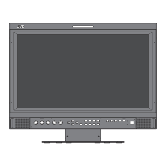
- Page 1 MULTI FORMAT LCD MONITOR DT-V17G15Z INSTRUCTIONS For Customer Use: Enter below the Serial No. which is located on the rear of the cabinet. Retain this information for future reference. Model No. DT-V17G15Z Serial No. LCT2698-001A...
- Page 2 Safety Precautions The lightning flash with arrowhead symbol, within an equilateral triangle is CAUTION intended to alert the user to the presence of uninsulated “dangerous voltage” RISK OF ELECTRICAL SHOCK within the product’s enclosure that may DO NOT OPEN be of sufficient magnitude to constitute a risk of electric shock to persons.
- Page 3 FCC NOTICE CAUTION: Changes or modifications not approved by JVC could void the user’s authority to operate the equipment. NOTE: This equipment has been tested and found to comply with the limits for a Class A digital device, pursuant to Part 15 of the FCC Rules.
- Page 4 If you wish to dispose of this product, please visit our web page http:// contain noise. In such cases, please keep the cable away from the www.jvc.eu/ to obtain information about the take-back of the product. sources of the disturbance.
- Page 5 Operating Precautions The LCD panel and backlight have life expectancy. Due to the basic characteristics of the LCD panel, an afterimage or uneven display may occur. It is recommended that you change images occasionally, activate the power saving function, or often turn off the power to reduce the load on the LCD panel.
- Page 6 Installation ● Do not rest your arm on the monitor or lean against the monitor. ● Do not touch the LCD panel when installing the monitor. ● Be sure to install the monitor securely to prevent the monitor from falling over, which may cause damage to the monitor or injury. ●...
- Page 7 ● To install the monitor on a shelf or any other suitable surface using screws You can install the monitor on a shelf etc. by changing the position of the bottom plate of the stand to a rearward position. CAUTION ●...
- Page 8 Index of Parts and Functions Front panel Tally lamp This lamp is controlled by the tally function of the MAKE/TRIGGER terminal. • You can select the color of the tally lamp from “GREEN” or “RED.” (☞ “TALLY SELECT” in “FUNCTION SETTING” on page 18 and “External Control” on page 22) •...
- Page 9 6 MENU button t INPUT SELECT buttons/lamps Activates/deactivates the display of the MAIN MENU Selects an input. (☞ “Menu Operations” on page 13). SDI 1: Input from the E. AUDIO SDI/HD SDI/ 7 COLOR OFF button/lamp SD SDI (IN 1) terminal SDI 2: Input from the E.
- Page 10 Index of Parts and Functions (cont.) Rear panel Carry handle Use this handle when carrying the monitor. Security slot Attach a security wire to this slot. Note for connections • Before making any connections, turn off all the equipment. • Use a cord whose plugs correctly match the terminals on this monitor and the equipment.
- Page 11 Showing Input Signals Audio Channel Selection Select audio channels emitted from the speakers (L/R) and the AUDIO (MONITOR OUT)(OUT1(L)/OUT2(R) terminals, when EMBEDDED AUDIO signals come in to the SDI terminal and SDI input is selected. ● You have to choose a group of selectable audio channels before the channel selection (☞ “E.AUDIO GROUP” in “AUDIO SETTING” on page 16). ●...
- Page 12 Showing Input Signals (cont.) On the Status Display If you press the INPUT SELECT button (☞ t on page 9) currently lit, the status of the input signal and setting of MUTING are displayed for about 3 seconds. ● Make the setting to display/hide the status in “STATUS DISPLAY” of the “INFORMATION.” (☞ page 20) ●...
- Page 13 Setting the menu Menu Operations MAIN MENU SET-UP MENU Item being Display the menu. selected To display the MAIN MENU ➔ Press MENU button. Operation To display the SET-UP MENU guide ➔ Press button while holding button. Press buttons to select an item, then press button. MAIN MENU ●...
- Page 14 Setting the menu (cont.) MAIN MENU PICTURE FUNCTION Setting for the picture quality. Item Content Setting value APERTURE * Activates/deactivates the function at the level set in “APERTURE LEVEL.” OFF, ON APERTURE LEVEL * Simultaneously corrects the frequency characteristics of the RGB colors. 01 –...
- Page 15 *1*2 MARKER Settings for marker functions. Item Content Setting value AREA MARKER * Activate/deactivate the area marker and select the style of it. The setting values and features are as follows. LINE HALF Deactivate the marker. HALF+L LINE Displays the area with an outline. BLK.
- Page 16 Setting the menu (cont.) AUDIO SETTING Settings for the audio output balance, EMBEDDED AUDIO signals and level meter. Item Content Setting value BALANCE Adjust the balance between the right and left speakers. L5 – L1, 0, R1 – R5 E.AUDIO GROUP * Select the audio channel group of the EMBEDDED AUDIO signals.
- Page 17 SCOPE SETTING Configure the settings for the wave form monitor and vector scope. Item Content Setting value GAIN Adjust the input gain level. –10 – +10 SIZE * Set the window size. NORMAL, LARGE POSITION * Select the window position. 1 (Lower right), 2 (Lower left) 3 (Upper left), 4 (Upper right) TRANSPARENT...
- Page 18 Setting the menu (cont.) SET-UP MENU FUNCTION SETTING Configure the sub menu display, the lighting color of the tally lamp, the brightness of the button lamps. Item Content Setting value sub menu POSI. “ ” LOWER1 Select the contents and displaying position of sub menu.
- Page 19 PICTURE SUB ADJ. Configure the standard level of image adjustment. Item Content Setting value CONTRAST * Adjust the standard level for the contrast adjusted with the CONTRAST knob on the – 20 – +20 front panel. BRIGHT * Adjust the standard level for the brightness adjusted with the BRIGHT knob on the –...
- Page 20 Setting the menu (cont.) REMOTE SETTING (☞ “External Control” on pages 22) Settings for the external control. Item Content Setting value SERIAL TYPE Select the input terminal used for external control by serial RS232C communication. RS485 PARALLEL TYPE Select the external control method for the MAKE/TRIGGER terminal. MAKE, TRIGGER, SET ☞...
- Page 21 CONTROL LOCK Setting value: OFF, VOL.LOCK, ALL LOCK Settings for disabling the buttons on the front panel. ● The following operations are not available when “VOL.LOCK” is selected. – VOLUME adjustment knob – Picture adjustment knob ● The “ALL LOCK” function disables to control the buttons on the front panel. But following operations are available. –...
- Page 22 External control About the external control Using the MAKE/TRIGGER This monitor has three external control terminals. system ● MAKE/TRIGGER terminal (RJ-45): The following external control The MAKE/TRIGGER terminal is configured as follows. systems are available. You can assign a function to each pin terminal in “REMOTE SETTING.” 1 MAKE (make contact) system: (☞...
- Page 23 <Functions controlled by the MAKE/TRIGGER system> Display Functions to be controlled Opening Short-circuiting TALLY SEL Selects the color of the tally lamp Green SDI 1 Changes the input to “SDI 1” Invalid Valid SDI 2 Changes the input to “SDI 2” Invalid Valid Changes the input to “DVI”...
- Page 24 External Control (cont.) Using the serial communication You can control the monitor from a personal computer etc. via the RS-485 or RS-232C terminal. ● Consult your dealer for the details of the external control specification. <Communication specifications> Terminal Input terminal Cable Communication specifications specification...
- Page 25 <Basic command list> Commands Functions Data ! * ** B C N 1 Cr Starts communication (connection) No data ! * ** B C N 0 Cr Terminates communication (termination) No data ! * ** B I D S Assigns the control ID 01 –...
- Page 26 Troubleshooting Solutions to common problems related to the monitor are described here. If none of the solutions presented here solve the problem, unplug the monitor and consult an authorized dealer or service center. Symptom Probable cause and corrective action Page ●...
- Page 27 Self-check program This monitor has a self-check function, which allows it to detect malfunctions and alert you. This makes troubleshooting easier. Whenever a problem occurs, one or some of the INPUT SELECT (DVI, COMPO., VIDEO) lamps will flash. If this happens, follow the steps below and contact your dealer to resolve the problem.
- Page 28 Specifications General Model name DT-V17G15Z Type MULTI FORMAT LCD MONITOR Screen size Type 17 wide format Aspect ratio 16:9 ☞ “Available signals” on page 29 Compliant video signal format Format 3G SDI SMPTE424M/SMPTE425M DUAL LINK HD SDI SMPTE372M HD SDI...
- Page 29 Notice on transportation This monitor is precision equipment and needs dedicated packing material for transportation. Never use any packing material supplied from sources other than JVC or JVC-authorized dealers. ● For easy understanding, pictures and illustrations are emphasized, omitted or composed, and may be slightly different from actual products.
- Page 30 Specifications (cont.) Computer signals (preset) DVI-D (HDCP) terminals Resolution Frequency Signal name Scan system Horizontal Vertical Horizontal (kHz) Vertical (Hz) VGA60 31.5 59.9 Non-interlace WVGA60 31.5 59.9 Non-interlace SVGA60 37.9 60.3 Non-interlace XGA60 1024 48.4 60.0 Non-interlace WXGA (1280) 1280 47.8 60.0 Non-interlace...
- Page 31 Attaching the power cord holder The provided power cord holder prevents accidental disconnection of the AC power cord from the AC IN terminal. The holder consists of two parts: the cord case and the case cover. To take off the case cover case cover cord case AC IN terminal...
- Page 32 LCT2698-001A © 2012 JVC KENWOOD Corporation...